NOREGON DLA+ 2.0 User manual


2
DLA+ 2.0 Adapter Family User’s Manual
License Agreement
Noregon Systems Inc. retains all ownership to the DLA+ 2.0 Adapter Family ( DLA+ 2.0, DLA+ 2.0 Wireless and the Trailer
Diagnostic Adapter) and its documentation. The DLA+ 2.0 Adapter Family ( DLA+ 2.0, DLA+ 2.0 Wireless and Trailer
Diagnostic Adapter) source code is a confidential trade secret of Noregon Systems, Inc. You may not decode or de-compile
the DLA+ 2.0 Adapter Family ( DLA+ 2.0, DLA+ 2.0 Wireless and Trailer Diagnostic Adapter) software, develop source code
for the DLA+ 2.0 Adapter Family ( DLA+ 2.0, DLA+ 2.0 Wireless and Trailer Diagnostic Adapter), or knowingly allow others
to do so. The DLA+ 2.0 Adapter Family ( DLA+ 2.0, DLA+ 2.0 Wireless and Trailer Diagnostic Adapter) and its
documentation may not be sublicensed or transferred without the prior written consent of Noregon Systems, Inc.
This publication, as well as the software it describes, is furnished under license and may only be used or copied in
accordance with the terms of such license. The content of this manual is provided for informational use only, is subject to
change without notice, and should not be construed as a commitment by Noregon Systems, Inc. Noregon Systems, Inc.
assumes no responsibility or liability for any errors or inaccuracies that may appear in this manual.
Without the prior written permission of Noregon Systems, Inc., except as permitted by such license, no portion of this
documentation may be reproduced, or transmitted, in any form or by any means, electronically, mechanically, or
otherwise.
©2019 Noregon Systems, Inc. All Rights Reserved. All other marks, trademarks or registered trademarks of the respective
holders. Pictures, figures and tables are for illustration purposes only. Product specifications are subject to change without
notification.
The DLA+ 2.0 Wireless adapter is compliant with Part 15 of the FCC Rules. The device contains an RF transmitter (ID 3867A
MTCHDRCT). THE FCC ID is R68 MTCHDRCT.
www.noregon.com

3
Installation Notes
Table of Contents
License Agreement.....................................................................................................................................................2
Table of Contents .......................................................................................................................................................3
The Noregon DLA+ 2.0 Adapter Family ..................................................................................................................4
LED Indicators.........................................................................................................................................................4
Product Specifications and System Requirements.....................................................................................................6
Supported Protocols and Standards.......................................................................................................................7
Supply Voltage........................................................................................................................................................7
Temperature...........................................................................................................................................................8
Electromagnetic Compatibility...............................................................................................................................8
Transient Protections .............................................................................................................................................8
Electro-Static Discharge Protection........................................................................................................................8
Installation Notes .......................................................................................................................................................9
Driver Installation................................................................................................................................................ 10
DLA+ 2.0 Wireless Configuration......................................................................................................................... 13
The DLA+ 2.0 Wireless Minder......................................................................................................................... 13
Configuring the DLA+ 2.0 Wireless Adapter (ASSY REV A.xx) .......................................................................... 14
Configuration on a Local / Corporate Network ............................................................................................... 16
Configuring the DLA+ 2.0 Wireless Adapter (ASSY REV B.xx) .......................................................................... 31
Establishing the Connection Between your PC and the Adapter........................................................................ 35
The Favorites Feature to Select IP Addresses ..................................................................................................... 37
Updating Adapter Firmware................................................................................................................................ 40
Automatic Firmware Update........................................................................................................................... 40
Manual Firmware Update ............................................................................................................................... 42
Wireless Reception Guidelines for DLA+ 2.0 Wireless ............................................................................................ 45
Testing Vehicle Connections.................................................................................................................................... 47
Frequently Asked Questions and Troubleshooting................................................................................................. 48
RP1210 Error Codes............................................................................................................................................. 49
Technical Support.................................................................................................................................................... 51
Appendix 1 –Windows 8/10 Configuration via Windows Mobile HotSpot............................................................. 52
Windows Mobile HotSpot Configuration ............................................................................................................ 52
4
DLA+ 2.0 Adapter Family User’s Manual
Adapter Configuration for DLA+2.0 Wireless Adapter (ASSY REV A.xx).............................................................. 53
Adapter Configuration for DLA+2.0 Wireless Adapter (ASSY REV B.xx) .............................................................. 55
Introduction
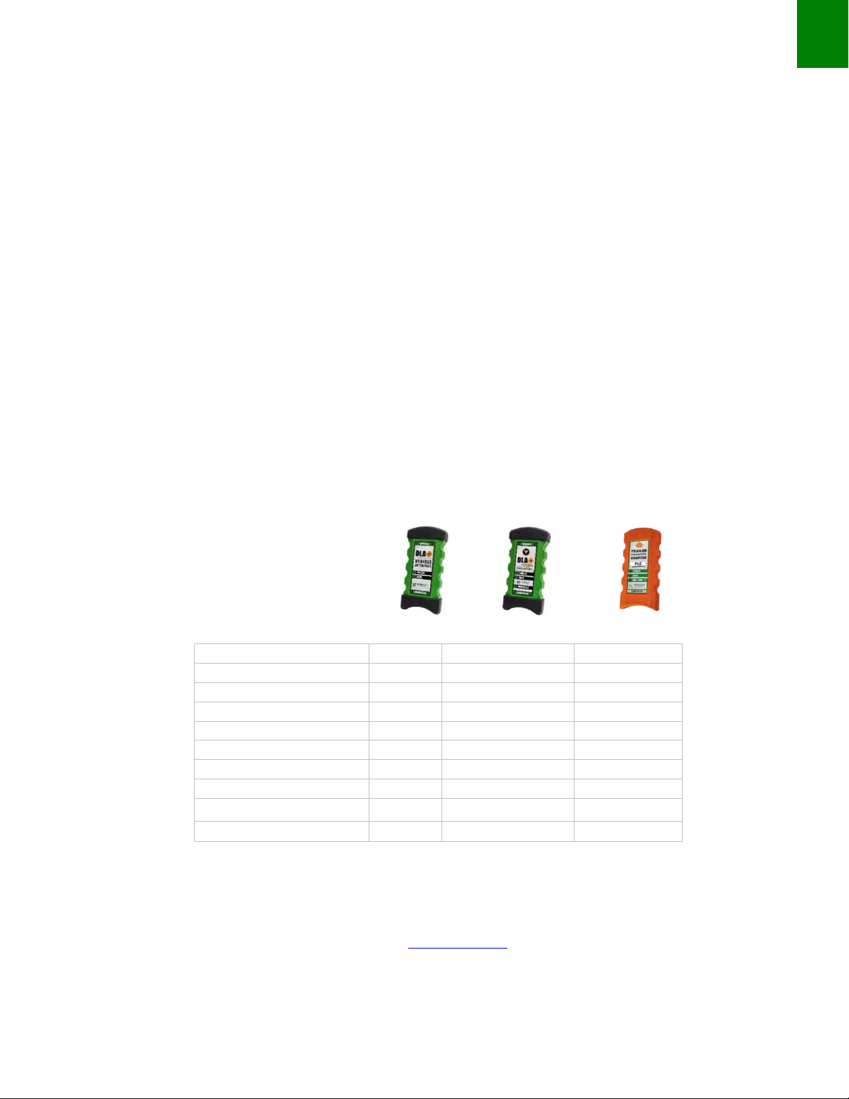
The Noregon DLA+ 2.0 Adapter Family
The Noregon DLA+ 2.0 Adapter Family ( DLA+ 2.0, DLA+ 2.0 Wireless Adapter and Trailer Diagnostic Adapters)
are diagnostic devices that communicate with vehicle data for display on a PC-based diagnostic software
application. Starting in 2016, CARB and EPA mandated standard that all vehicles support 500K J1939, resulting in
the development of a new Type-2 9-pin connector. This connector can have up to 3 CAN channels (Tri CAN).
The DLA+ 2.0 and DLA+ 2.0 Wireless adapters and their cables will work with all existing vehicles and with newer
vehicles that will have the Type-2 9-pin connector.
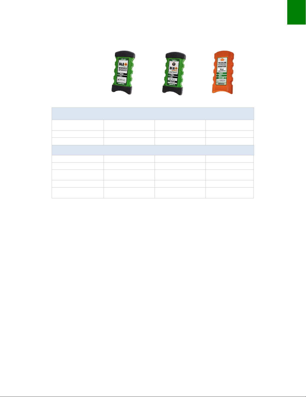
LED Indicators
Noregon DLA+ 2.0 Adapter Family of products will support different LED indicators. The following table defines
the LEDs and meaning per adapter:
J1708
X
X
Tri CAN/J1939
X
X
K-Line (KWP, ISO9141)
X
X
J1850 (VPW –GM)
X
X
J2497 / PLC4Trucks
X
USB Connectivity
X
X
X
Wireless (802.11 b/g)
X
Firmware updates (via USB)
X
X
X
Power (from Vehicle)
X
X
X
Power (from USB)
X
X
NOTE: Instructional materials are also found on the installation USB flash drive or on the
“Resources” section of www.Noregon.com website.
DLA+ 2.0
DLA+ 2.0 Wireless
Trailer Diagnostics

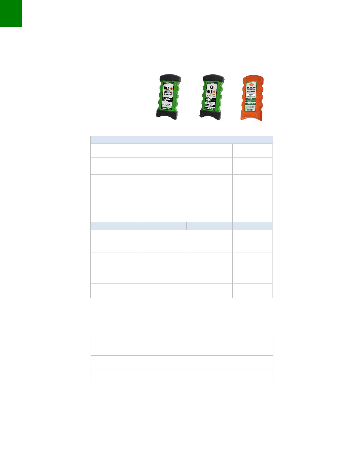
5
Installation Notes
Adapter
Green LED
(Power)
Red LED
(Data)
Red LED
(ABS AMP)
Red LED
(Wireless)
DLA+ 2.0
X
X
N/A
N/A
DLA+ 2.0 Wireless
X
X
N/A
X
Trailer Diagnostics
X
X
X
N/A
POWER (green) LED:
1. Off when no power is applied.
2. Illuminates green when vehicle or USB side power is supplied.
DATA (red) LED:
1. Flashes red once per second (heartbeat) to indicate Adapter is ready for use and no data is being
transmitted on the device (DLA+ 2.0 and DLA+ 2.0 Wireless only).
2. Flashes steady red when the device is reading data regardless of protocol.
ABS Lamp (red) LED: (TDA adapter ONLY)
1. The device acts like the tractor ABS light and will follow the SAE J2497 standard.
WIRELESS (red) LED:
1. Indicates wireless network (802.11) association.
2. Solid lit LED when adapter is connected to a wireless network.
3. ASSY REV B.xx hardware wireless LED:
a. Fast Blink: Reboot/Error. This happens briefly when the wireless reboots. If it persists then the
wireless cannot ‘init’the Wi-Fi subsystem.
b. Single Blink: Adapter is in Stand-alone Access Point mode but not connected.
c. Double Blink: Adapter is in Infrastructure mode but not connected.
d. Solid on: Adapter is connected to Wireless network (Peer to Peer OR Infrastructure mode).
6
DLA+ 2.0 Adapter Family User’s Manual
Product Specifications and System Requirements
32-Bit Operating System Requirements
Windows 7 Pro (current
service pack)
X
X
X
Windows 8
X
X
X
Windows 10
X
X
X
32-bit Minimum PC Requirements
Pentium IV or faster
X
X
X
1 GB RAM
X
X
X
100 MB free hard disk space
X
X
X
1 free USB 2.0 port
X
X
X
Wireless PC card required
X
Trailer Diagnostics
DLA+ 2.0 Wireless
DLA+ 2.0
7
Installation Notes
Supported Protocols and Standards
RP1210 Protocols
CAN
(GMLAN, J2284)
X
X
J1708/J1587
X
X
J1850 (VPW –GM)
X
X
J1939
X
X
ISO 15765
X
X
ISO 9141-2
X
X
ISO 14230
(KWP2000)
X
X
PLC
X
J2534 Protocols
CAN (Raw CAN)
ISO 11898
X
X
GMLAN (HSCAN)
X
X
ISO 9141-2
X
X
ISO 14230
(KWP2000)
X
X
ISO 15765-4
X
X
J1850 VPW
(GM Class II)
X
X
Supply Voltage
The following table specifies the voltage required by the DLA+ 2.0 Adapters.
Vehicle Input Voltage
Range
9-36 VDC
USB Voltage
5.0 VDC
Current Consumption
No more than 500mA
DLA+ 2.0
DLA+ 2.0 Wireless
Trailer Diagnostics

8
DLA+ 2.0 Adapter Family User’s Manual
Temperature
The DLA+ 2.0 Adapters shall operate over the following temperatures and meet all of its functional and
performance specifications.
Storage Range
-40to 176F
(-40to 80C)
Operating Range
0to 149F
(-18to 65C)
Electromagnetic Compatibility
The DLA+ 2.0 Wireless Adapters comply with FCC Part 15 technical standards regarding electromagnetic
radiation.
Transient Protections
The DLA+ 2.0 Wireless Adapters are designed to meet SAEJ1455 requirements for 12-volt systems.
Electro-Static Discharge Protection
The DLA+ 2.0 Wireless Adapters are designed to meet SAEJ1455 for 12-volt systems.
WARNING:
DO NOT ATTEMPT TO USE REPROGRAMMING FEATURES
WHILE IN WIRELESS MODE (use USB mode).
NOTE: Check the www.Noregon.com website for the very latest product specifications and system
requirements.

9
Installation Notes
Installation Notes
Before installing drivers and adapters, note:
•Installation requires administration privileges.
•Installation steps (and subsequent screens) will vary based on user systems (Windows OS version) and
type of adapter being installed. Most illustrated installation steps are for a DLA+ 2.0 Wireless Adapter.
•Installation files can be accessed using a USB flash drive or online at
http://www.noregon.com/adapter-drivers.
Insert the DLA+ 2.0 Driver USB Flash drive or the Professional USB flash drive into your USB port or download
the latest adapter drivers from http://www.noregon.com/adapter-drivers.
If using the supplied USB flash drive, the installation program will begin automatically. Click the Install Adapter
Drivers button to begin.
If using drivers downloaded from the website, begin the installation process by running the downloaded file.

10
DLA+ 2.0 Adapter Family User’s Manual
Driver Installation
Periodically check http://www.noregon.com/adapter drivers for the latest driver updates.
1. If the install program does not start automatically, start the program by running the Application.exe.
2. When the User Account Control box appears, select Yes to launch the install.
3. The Installer will appear, select Install to begin.
Figure 1
NOTE: The screen shown in the example reflects installing a DLA+ 2.0 Wireless Adapter; however, the driver installation
steps for all DLA+ 2.0 Adapters are the same.
4. This screen appears; select the Next button.
Figure 2
11
Installation Notes
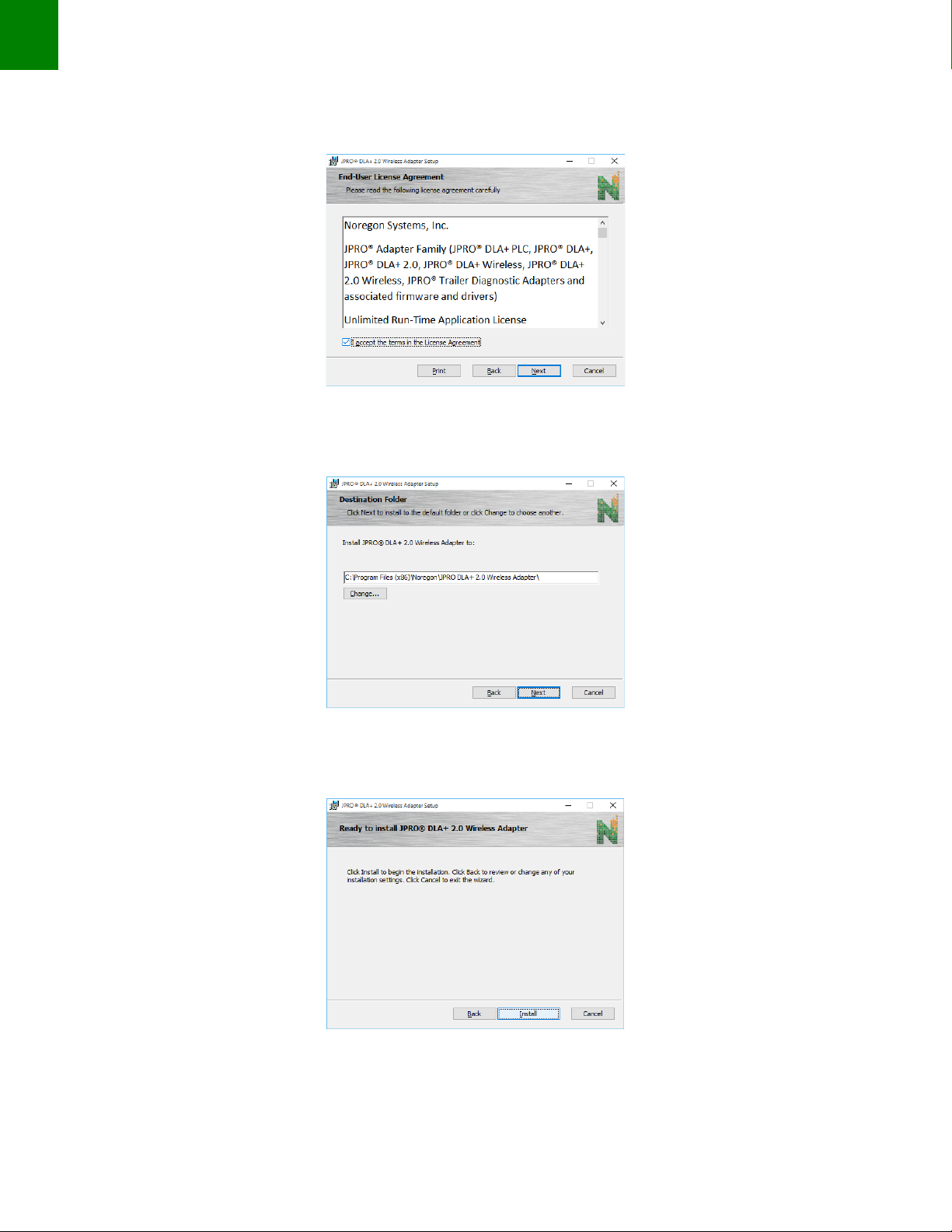
5. Click the check box to accept the License Agreement and click the Next button.
Figure 3
6. Click the Next button.
Figure 4
7. Click the Install button.
Figure 5
12
DLA+ 2.0 Adapter Family User’s Manual
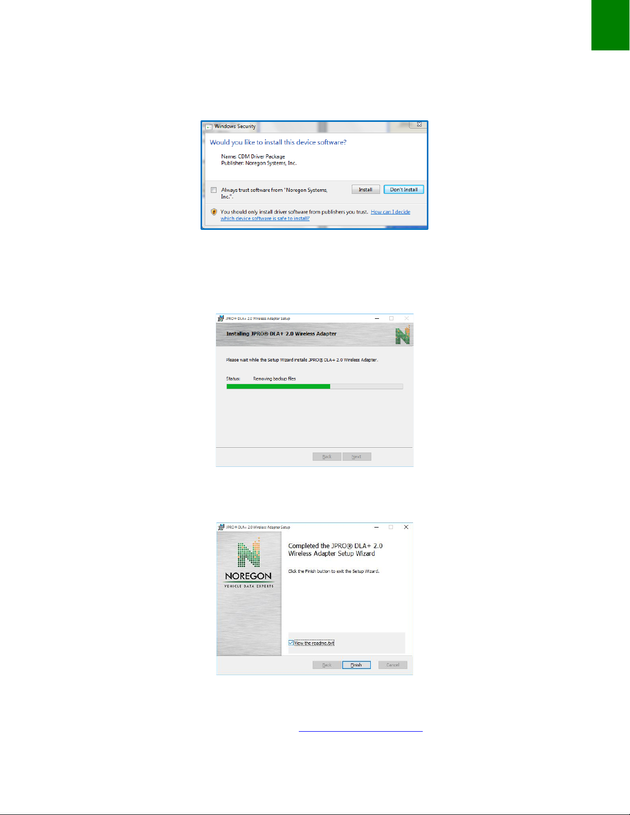
If your system displays a security window (screen shot for illustration) again click the Install button.
Figure 6
8. The installation procedure will continue.
Figure 7
Click the Finish button.
Figure 8
Once the latest drivers are installed, you can connect the adapter to the computer via USB cable and begin to
use you DLA+ 2.0 Family adapter. Please proceed to configure Wireless settings if applicable.
13
Installation Notes
DLA+ 2.0 Wireless Configuration
Before beginning wireless configuration, check the “Resources” section of the www.Noregon.com website for
any notes or changes to the DLA+ 2.0 Wireless configuration process.
You must first install the necessary drivers before configuring the DLA+ 2.0 Wireless Adapter to work with your
PC for diagnostic applications. Please be sure to follow the instructions in the Installation section beginning on
page 10.
NOTE: Identify which DLA+ 2.0 Wireless Adapter you have… (ASSY REV A.xx)or (ASSY REV B.xx).The ASSY
REV information is found on the label containing the barcode. Follow the appropriate Wireless Configuration
section.
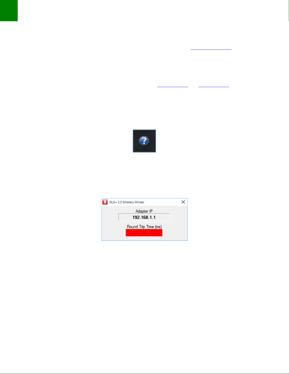
The DLA+ 2.0 Wireless Minder
After drivers are installed, your System Task Bar displays the DLA+ 2.0 Wireless Minder icon (if your system is set
to display Task Bar icons).
Figure 9
If you scroll your cursor over the icon, the message, “DLA+ 2.0 Wireless Minder: No Adapter IP Found” will
appear.
If you right click on the icon and select “Show Details”, a box will display that your DLA+ 2.0 Wireless Adapter is
not yet configured and therefore not getting a signal as indicated by the red “Round Trip Time (ms)” status bar.
Figure 10
Once you have configured and assigned an IP address to the DLA+ 2.0 Wireless Adapter, connected to a wireless
network, and the reception is strong, the status bar will become green as seen in Figure 52 on page 53.
As just noted, even after you have configured your DLA+ 2.0 Wireless Adapter to a wireless network, you may
get a poor transmission signal. To ensure a stronger signal, you may need to move your PC and DLA+ 2.0
Wireless Adapter closer to each other (See Wireless Reception Guidelines pages 64-65).
NOTE: Before setting up a connection between your PC and the DLA+ 2.0 Wireless Adapter, you must know if
you will use a local / corporate network or peer-to-peer connection. It is recommended you contact your
network administrator for local / corporate network configuration.
14
DLA+ 2.0 Adapter Family User’s Manual
Configuring the DLA+ 2.0 Wireless Adapter (ASSY REV A.xx)
To configure the adapter for the first time, or to change its network settings, follow these steps:
NOTE: If you have already installed your drivers (see page 10), Steps 1 and 2 may already be complete.
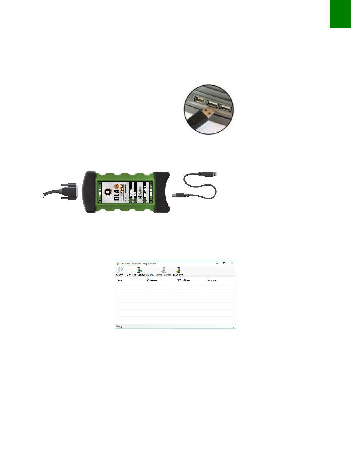
1. Plug the USB cable into the USB port on the PC.
2. Connect the other end of the USB cable to the port labeled Computer on the adapter. Connect the
diagnostic cable to the 26-pin connector and attach the diagnostic cable connector to the diagnostic
port on the vehicle.
3. You will see the “Wireless” LED flash and then stop while the “Data” LED pulses regularly indicating the
adapter is ready for a data connection. From the Start menu, if DLA+ 2.0 Wireless Configuration Tool
does not automatically appear in the list of programs, go to Noregon and open JPRO® DLA+ 2.0 Wireless
Configuration Tool.
Figure 11
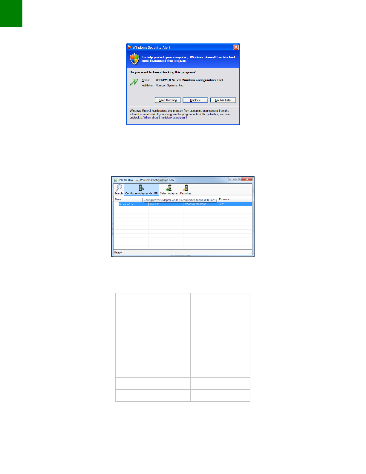
NOTE: Depending on your system security settings, you may receive a Windows Security Alert like the one in
Figure . If so, verify the name of the program in the alert is the JPRO® DLA+ 2.0 Wireless Configuration Tool
and click the Unblock button.
15
Installation Notes
Figure 12
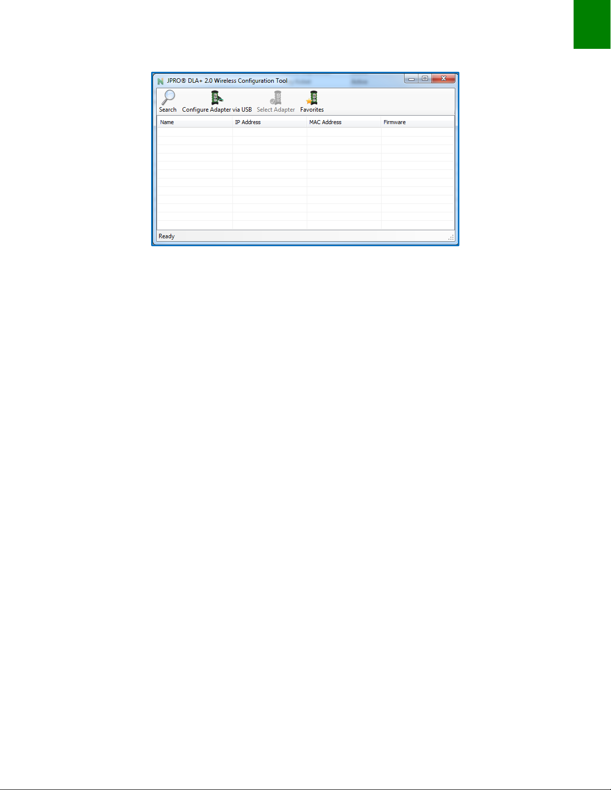
4. Click the Configure Adapter via USB button on the toolbar (see highlighted box in Figure ).
Figure 13
Below are default settings that will appear while configuring your DLA+ 2.0 Wireless Adapter:
Network Name (SSID)
LTRX_IBSS
Network Type
Peer-to-Peer
Channel
11
Security
None
IP Address
192.168.2.100
Subnet Mask
255.255.255.0
Gateway IP
0.0.0.0
DNS Server IP
0.0.0.0
Adapter Name
DLAWIR32
ASSY REV A.xx Default Wireless Settings
Table 1
16
DLA+ 2.0 Adapter Family User’s Manual
Configuration on a Local / Corporate Network
NOTE: If you are configuring your DLA+ 2.0 Wireless Adapter to connect to a local / corporate network, it is
highly recommended to consult your network administrator.
NOTE: For editing your DLA+ 2.0 Wireless Adapter, your administrator can refer to defaults on page 15.
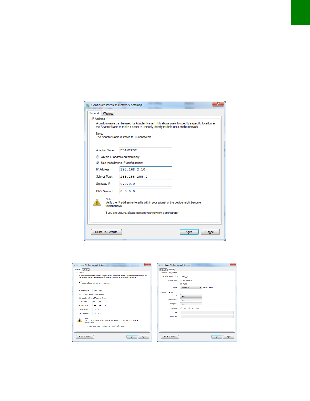
Once you have clicked Configure Adapter via USB, this screen will appear.
Figure 14
Toggle between the Network and Wireless tabs where the default settings display.
Figure 15

17
Installation Notes
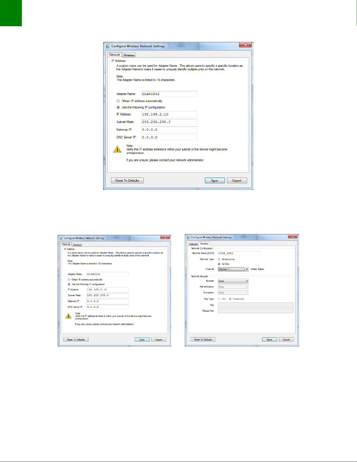
5. On the Network tab enter the assigned IP address from your network administrator as well as the values
for the Subnet Mask, Gateway IP and DNS Server IP. You can also modify the default adapter name.
6. Toggle to the Wireless tab and enter the Network Name (SSID) provided by your administrator. Then, at
Network Type, select the radio button, Infrastructure.
Figure 16
7. Select the appropriate Security option from the drop down in the Security field.
8. Enter the Network Security values. Authentication, Encryption, Key Type, Key and Retype Key then click
Save.
10. After selecting OK, this screen will appear indicating your DLA+ 2.0 Wireless Adapter is configured and
ready to connect with your PC once a network connection is established. (Establishing the Connection
Between you PC and the Adapter)
18
DLA+ 2.0 Adapter Family User’s Manual
Figure 17
You can minimize this screen, so it will be available after you have established your wireless network and are
ready to connect to your DLA+ 2.0 Wireless Adapter.
Configuration on a Peer-to-Peer Network
Configuring a DLA+ 2.0 Wireless Adapter on a peer-to-peer network means the DLA+ 2.0 Wireless Adapter will
communicate with your PC without going through a local / corporate Wireless network.
Once you have clicked Configure Adapter via USB, this screen will appear.
19
Installation Notes
Figure 18
Toggle between the Network and Wireless tabs where the default settings display.
Figure 19 Figure 20
From the Network tab, ensure the last 3 digits in the IP Address field are unique (numbers can only be from 1 to
255).
20
DLA+ 2.0 Adapter Family User’s Manual
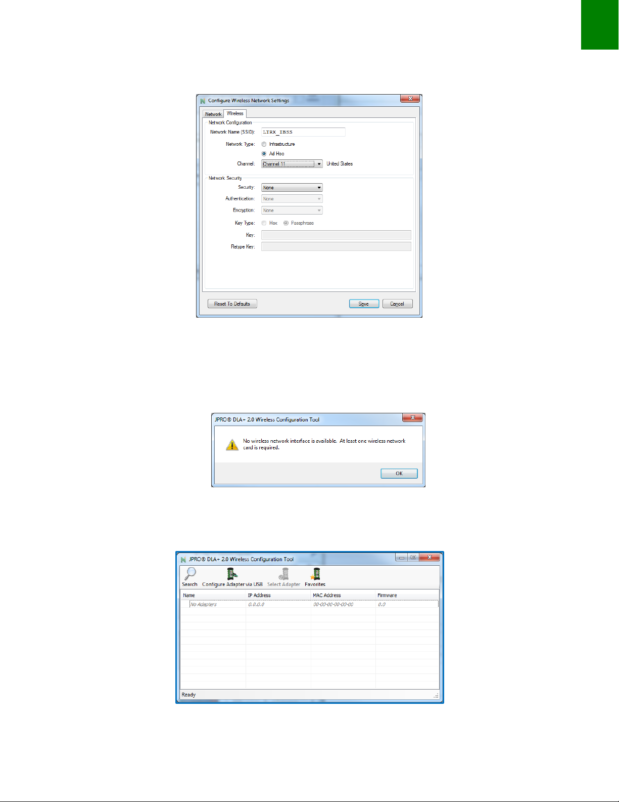
1. Toggle to the Wireless tab and note the default settings for the DLA + 2.0 Wireless Adapter.
Figure 21
2. Click the Save button to commit the settings to the DLA+ 2.0 Wireless Adapter.
3. Select OK on the below dialog.
Figure 22
4. After selecting OK, this screen will appear indicating your DLA+ 2.0 Wireless Adapter is configured and
ready to connect with your PC once a network connection is established.
Figure 23
Other manuals for DLA+ 2.0
1
This manual suits for next models
1
Table of contents
Other NOREGON Adapter manuals


Popular Adapter manuals by other brands


StarTech.com
StarTech.com ICUSB232PROC quick start guide

TP-Link
TP-Link TL-WN881ND Quick installation guide

Emulex
Emulex LP1050Ex Installation and reference manual

Lenovo
Lenovo ThinkSystem RAID 930-16i Installation and user guide

Motorola
Motorola HS830 HANSFREE quick start

NETGEAR
NETGEAR WG121 - 54 Mbps Wireless USB 2.0 Adapter installation guide