AudioShare ASA468 User manual
The First all digital Voice and Music system
USER
GUIDE
v01r02-080917
Retrofit Adapter
Model ASA468
© 2008 Digital Home Communications, LLC. All Rights Reserved.

2
Important Safety Information
WARNING: To prevent fire or shock hazard or damage to the
equipment, do not expose this equipment to rain or excessive
moisture.
FEDERAL COMMUNICATIONS COMMISSION (FCC)
WARNING:
Unauthorized modifications to this equipment not only void the
warranty, but also void the user’s authority to operate it.
WARNING: There are no user or installer serviceable parts in any
audioShare®devices. Do not disassemble any devices or attempt to
repair or replace components. Doing so may damage the device or
cause it to cease functioning properly. The user warranty will also be
voided.
WARNING: Even though Cat. 5 wiring and RJ45 connections are
used to interconnect devices, the audioShare®system uses a
proprietary networking scheme and is NOT COMPATIBLE with
Ethernet devices. Unless otherwise specified, connecting any
audioShare®compatible device (wall stations, door stations, hubs,
power injector modules, etc.) to Ethernet compatible devices will
result in damage to the audioShare®device, the Ethernet device, or
both. Resulting damage is not covered under the warranties of
either type of device.
WARNING: audioShare®devices contain complex electronic
circuitry that is highly sensitive to electrostatic discharge (ESD).
audioShare®units have been designed to shunt electrostatic
discharge away from these sensitive circuits. In order for this
protection to be fully effective, the audioShare®system power
supply must be connected directly to an electrical/earth ground.
Failure to properly ground the system will void the warranty.

3
WARNING: Use only the certified audioShare®power supply
provided with the system. Use of unauthorized power supplies may
cause erratic, diminished or unsafe operation and will void the
warranty.
CAUTION: The audioShare®system power supply operates at 50
VDC, which is present on all system wiring and at each device
connected to the system. Disconnect system power supply before
installing, interconnecting, replacing or removing any audioShare®
equipment. It is possible for 50 VDC to still be present on
audioShare®devices for several minutes after power has been
disconnected.

4
The First all digital Voice and Music system
ASA468 ADAPTER
USER GUIDE
Table of Contents
INTRODUCTION .........................................................................................5
What’s a Media Bus?................................................................................5
INSTALLATION AND CONFIGURATION ...............................................6
WIRING RECOMMENDATIONS ...............................................................8
Wires That Don’t Work.............................................................................8
MOUNTING..................................................................................................9
TESTING .......................................................................................................9
SPECIFICATIONS......................................................................................10
WARRANTY...............................................................................................11
DHC Limited Warranty........................................................................11
How to Obtain Warranty Service.........................................................11
Customer Feedback..............................................................................11
CONTACT INFORMATION......................................................................12

5
INTRODUCTION
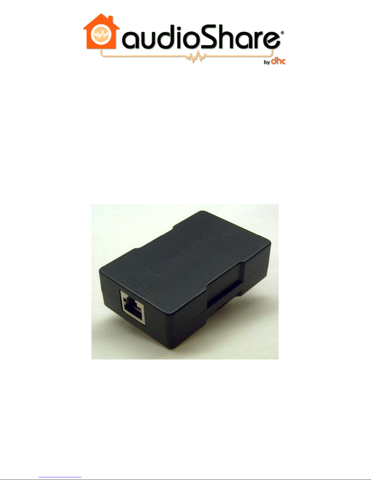
The audioShare®ASA468 Adapter is designed for retrofit installations where
existing wiring is not compatible with the standard Cat 5 cable and/or RJ45
connectors. It is meant to allow operation of audioShare®devices with 4, 6 or 8-
wire twisted pair cables. audioShare®devices normally require 8 wires (4 twisted
pairs): 2 for power, 2 for data bus (control and address), and 2 for each of the two
media buses (digital bit streams). The ASA468 Adapter provides answers for two
problems created by most retrofit wiring. First, it allows wiring with gauges larger
than 24 AWG to be attached to a standard RJ45 connector for connection to the
audioShare®devices. Second, it allows media bus number 1 to be transmitted
over the pair that also provides power to the devices, thus the audioShare®system
can still operate with both media buses on a 6-wire cable or it can operate with one
media bus on a 4-wire cable. Thus many existing cables can be used as long as the
pairs are twisted or are individually shielded. audioShare®WILL NOT work with
non-twisted “ribbon” type or bundled cables since there is no way to control the
impedance or crosstalk issues.
What’s a Media Bus?
audioShare®sends the audio signals from one station to another using patent-
pending Media Networking technology, over what is called a Media Bus. It was
designed with two media buses so you can have two different combinations of
stations doing two different things at once. You can have 2 voice communications,
or 1 voice communication and 1 music broadcast, or 2 music broadcasts going on
at the same time without interfering with each other. Individual stations can only
perform one function at a time, however, i.e., either music or intercom. As
mentioned above, a 4-wire cable only allows for 1 media bus.
The ASA468 Adapter is a passive device meaning that it has no active components
that require external power for operation; therefore it draws no power from the
system. It is, however, protected against electrostatic discharge (ESD) and certain
types of power line spikes.

6
INSTALLATION AND CONFIGURATION
The ASA468 Adapter has two terminal connection methods. A standard female
RJ45 jack is supplied on one end which can be attached to any audioShare®
device by using an appropriate length of Cat 5 cable, terminated at both ends with
male RJ45 plugs using standard EIA/TIA568B wiring configuration. The other
end has an 8-position Phoenix-type screw terminal block where the non-standard
cable can be attached. Wires should be attached in twisted or shielded pairs. The
first pair between pins 1 and 2, the next pair between pins 3 and 4, etc. The
diagram below shows the pin configuration. Pins 1 and 2 of the terminal block are
for power, pins 3 and 4 are for the data bus, pins 5 and 6 are for Media Bus 2, and
pins 7 and 8 are for Media Bus 1.
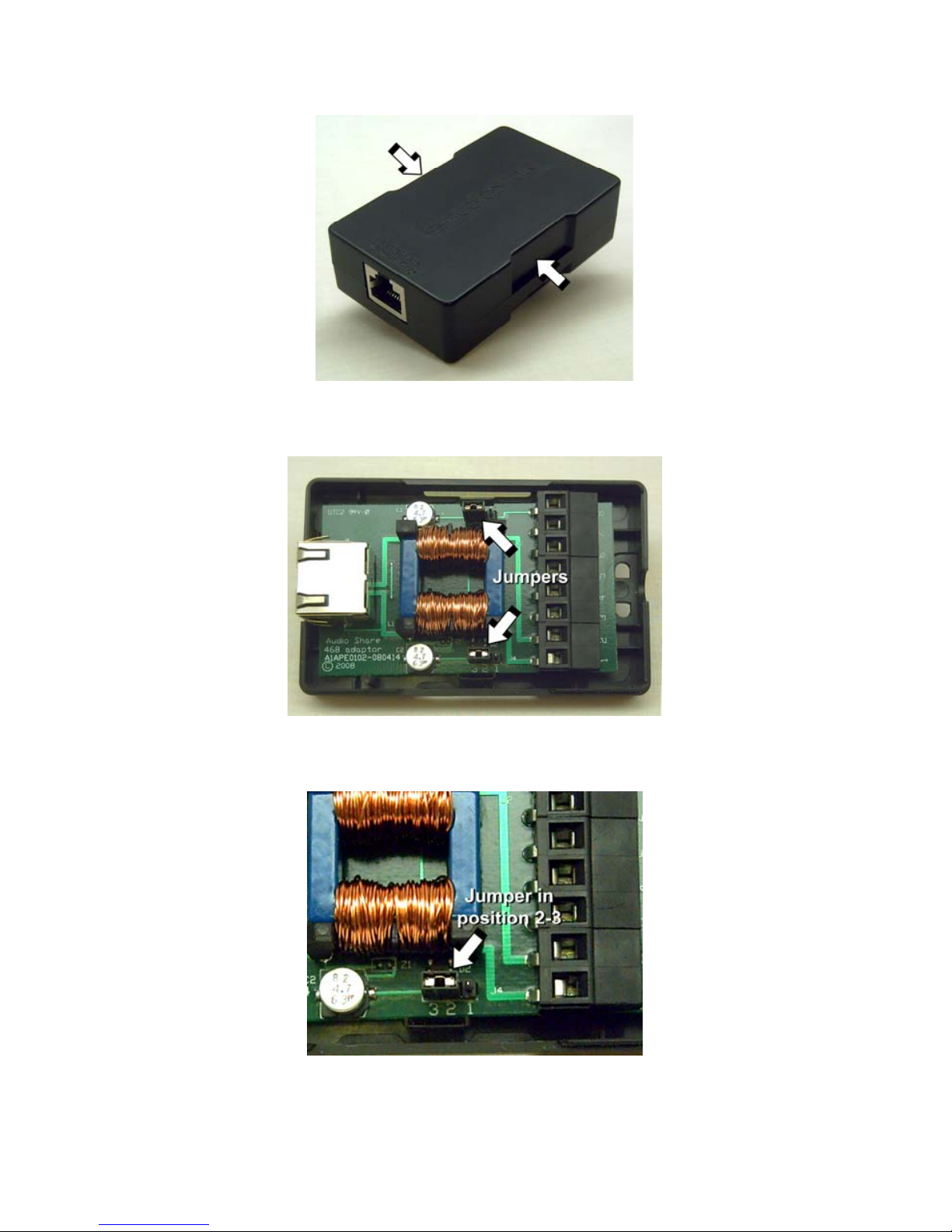
Just behind the terminal block are two jumpers (See Figure 2). These jumpers
determine whether Media Bus 1 is transmitted over pins 7 and 8 (normal
operation) or over the power pair, pins 1 and 2.
The following table shows the various wiring and jumper configurations for 4, 6
and 8-wire cables.
Pin # Description 8 Wires 6 Wires 4 Wires Jumpers
Pos. 1-2 Jumpers
Pos. 2-3
1 Power - ●●●●
2 Power + ●●●●
3 Data Bus - ●●●●
4 Data Bus + ●●●●
5 Media Bus 2 - ●●●
6 Media Bus 2 + ●●●
7 Media Bus 1 - ●●
8 Media Bus 1 + ●●
When using 8 wires, the jumpers should be installed in position 1-2. For 6 or 4
wire cables, the jumpers should be installed in position 2-3.
Jumpers are changed by opening the protective cover (see Figure 1) and simply
grabbing the end of each jumper with a pair of needle-nose pliers and pulling them
off of the header, then sliding them back on in the proper position (see Figure 3).
After configuring the jumpers and installing the wires and a cable tie (if desired),
snap the protective cover back in place.
7
Figure 1. Squeeze sides at arrows to release top cover.
Figure 2. Jumper Locations.
Figure 3. Jumpers in position 2-3 for 4 or 6-wire operation.

8
WIRING RECOMMENDATIONS
With the ASA468 Adapter, several wire types can be used. There are only a few
simple rules to follow, mostly for safety and/or operational integrity reasons. The
following wire types have been tested and represent a large majority of wire types
that may be encountered in retrofit installations.
M&S MS4XSC – 22 ga., 2-pair solid conductors with individual shields and gray
outer insulation (essentially, 2 sets of high grade differential audio cable in one
sheath), used for M&S wall stations. This cable can be used as 3 pairs by taking
advantage of the 2 shield (drain) wires which are insulated from each other as long
as the inside ends of the individual foils or the wires themselves don’t touch each
other.
When using as 2-pair cable only, simply use the individual pairs and leave the
shields unconnected. This will only allow for one media bus operation.
The shield wires can be used as a third pair thus allowing the second media bus
operation. Our recommendation is to use one of the pairs for power (pins 1&2)
and the second pair for media bus 2 (pins 5&6). The shield wires should then be
used for the data bus (pins 3&4) since it operates at a lower frequency and is less
susceptible to the impedance mismatch created by the shield wires. The individual
shield wires should be insulated with a sleeve to keep them from shorting together.
Another sleeve (e.g., heat shrink tubing) should be installed over the end of each
foil to prevent them from touching each other. It is highly recommended that the
shield wires not be used as the power conductors (pins 1&2) since, if they do short
together, the resulting damage would be far worse than if the data bus shorted out.
M&S MS4DCXSC – 22 ga. 2-pair solid conductors with individual shields and
orange outer insulation, used for M&S door stations. See MS4XSC, above.
Nutone IW-6 – 22 ga. 3-pair solid conductors. This cable is excellent in
retrofit installations since it works well with the ASA468 Adapter and no
special precautions are needed.
Wires That Don’t Work
The following wire types have been tested and WILL NOT WORK:
Nutone IW-4
M&S MS4X - 22 ga. 4 conductor flat ribbon cable
M&S 7-conductor for discontinued model 902

9
Using Existing Telephone Wiring
The ASA468 Adapter can be attached to unused pairs in existing analog telephone
cables. For example, let’s say a house is already wired for telephone to each room
where an intercom is desired. If Cat 5 or other 4 pair cable is being used for a
single line telephone the remaining three pairs can be used for audioShare®units
allowing for 2 media bus operation without interfering with normal telephone
service or vice-versa. Simply connect an ASA468 Adapter to each end of the
unused pairs, connect the audioShare®units and you’re ready to go.
If both telephone lines (1 & 2) are being used, you can still operated with one
media bus using the two remaining pairs.
MOUNTING
The ASA468 Adapter should be mounted behind the wall surface, i.e., behind
drywall or paneling or brick or stucco, etc. where it is protected from heat and
weather. It should not be exposed to excessive moisture or direct sunlight which
can corrode the contacts thus preventing proper electrical continuity.
Make sure the wires are securely clamped into the screw terminals and that the
wire insulation has not been stripped too far back so as to cause adjacent bare
wires to touch each other. Holes for cables ties are provided for strain relief.
TESTING
Test each Cat 5 cable with attached RJ45 connectors you are using to connect
between each audioShare®unit and the ASA468 Adapter using a standard
Ethernet cable tester to verify integrity before installing and applying power to the
system.
Because of reactive components within the ASA468 Adapter circuitry, it is not
possible to test the cables connected between the ASA468 Adapters with an
Ethernet cable tester, even when configured for an 8-wire cable. Therefore it is
extremely important to make absolutely certain that the wire connections to the
screw terminal connector are accurate at both ends. A simple continuity test is
recommended prior to connecting the non-standard cable to the ASA468 Adapter.

10
SPECIFICATIONS
System
Maximum Cable Length (from Hub to farthest unit or between two farthest units when using PEM/PIM):
Cable Type (recommended) 8 conductor Cat 5 or better - up to 500'
Cable Type (alternate) 4, 6 or 8 conductor twisted pairs - up to 300'
ASA468 Adapter
Power Consumption None (passive device)
Connections
Non-standard cable connection (1) Phoenix Type Screw Terminal Strip, 8-pins
System Network (1) RJ45 Female, 8-pins (Data, Media Buses & Power)
User Interface
4, 6 or 8 wire operation selection (2) Jumpers, located on PCB
Physical Dimensions 3-1/8” L, 2” W, 15/16” H

11
WARRANTY
DHC Limited Warranty
Digital Home Communications, LLC (DHC) warrants the audioShare®system
and components of our manufacture, when installed by certified audioShare®
installers, to be free of defects in materials and workmanship for a period of five
(5) years from the date of installation. DHC will, as its sole obligation under this
warranty, replace or repair, at our option and at no charge, any component or unit
that fails to operate within specified parameters within the warranty period. No
other warranties are expressed or implied.
This warranty does not cover defects in appearance or cosmetic or decorative
properties.
DHC assumes no liability for consequential or incidental damages relating to the
use or performance of our products. The laws regarding your rights under this
warranty vary from state-to-state and may apply differently depending on where
you live.
How to Obtain Warranty Service
Before returning any audioShare®unit you must first obtain a return
authorization (RA) number. Contact Support at the number listed on the last page
of this manual. You may then return the unit to your local authorized dealer or
directly to DHC. You will be given the appropriate address and shipping
instructions at the time you obtain the RA number.
Customer Feedback
DHC has gone to great lengths to design a reliable and user-friendly system that
should last for many years. No matter how hard we try, however, things can still
go wrong. Unlike some of our competitors who sell you the system and then walk
away, we want you to continue to use and feel good about your audioShare®
system for a long time, even after the warranty expires. If you don’t contact us
about problems, we can’t address or correct them. Please use the Customer
Feedback option under Support on our website, or call us or write to us and let us
know what problems you are experiencing (you can tell us the good stuff too).

12
The First all digital Voice and Music system
CONTACT INFORMATION
Main Office
DHC, LLC
873 S. Orem Blvd., Suite 1
Orem, UT 84058
Voice 1-888-406-7776
FAX: 1-877-642-9910
User or Installer Support
Phone: 1-801-615-7188
Sales
e-mail: BJarvis@audioshare.net
Phone: 1-888-406-7776
Website
www.audioshare.net
Table of contents


