Norfield 250MX User manual

OWNERS MANUAL
Release: 3
250MX
STRIKE JAMB ROUTER
Eective S/N: SR-3210MX Document Number: 17-346

2
First Release: April, 2008
Second Release: May, 2008
Third Release: November, 2015

3
Noreld Industries
P.O. Box 459
Chico, Ca. 95927
Technical Support: (530) 891-4214 - Parts: (800) 824-6242
Serial Number: _____________________
Date Purchased: _____________________
Noreld Industries
is the name that represents Quality, Reliability, Support, Innovation
and True Customer Service. We have been dedicated to providing quality products and
excellent customer service for more than 40 years.
Noreld Industries
has earned a repu-
tation in the pre hanging industry for seing standards for reliable machinery, full techni-
cal support, machine parts, full line industrial woodworking tools and supplies and a team
of customer care representatives to support you! Our factory-trained technical personnel
are ready to assist you on the telephone or in your shop.

4
This Page is Intentionally Blank

5
TABLE OF CONTENTS
Safety
Lockout Procedures
Specications
Location of Major Components
Section 1 - Installation & Setup
Section 2 - Operation
Section 3 - Adjustments
Section 4 - Maintenance
Parts & Assembly Schematics
Warranty & Parts Replacement Policy
Contact & Order Information
6
9
11
12
13
14
15
19
20
28
29

6
SAFETY
Safety considerations are an important element
of machine installation and operation. Actively
maintaining a safety mindset about yourself and
others while working around or on the
equipment is of primary importance. Operators and
maintenance personnel should refer to the safety informa-
tion on the following pages to familiarize themselves with
warning labels and practices providing for safe operation
and servicing of this machine.
Danger indicates an imminently hazardous situation, which if
not avoided WILL result in death or serious injury.
Warning indicates a potentially hazardous situation which, if
not avoided, COULD result in death or serious injury.
Caution indicates a potentially hazardous situation which, if
not avoided MAY result in minor or moderate injury. It may
also be used to alert against unsafe practices.
Caution, without the safety alert symbol, indicates a poten-
tially hazardous situation which, if not avoided M AY result in
property damage but not personal injury.
Notice indicates important information that if not followed
may CAUSE damage to the equipment.
Mandatory Action conveys an action step that should be
taken to avoid the hazard.
SAFETY

7
SAFETY
Do not operate this machine unless all guards are in place and working cor-
rectly. If any guards or hazard labels are missing or damaged call Noreld’s
Service Department immediately and request a replacement at (800) 824-6242.
Read and understand the operator’s manual before using this machine. Fail-
ure to follow proper operating instructions could result in death or serious
injury.
This machine, when in operation, produces wood chips and dust. The op-
erator and all persons in the work area MUST wear approved eye protection
with permanently aached, rigid plastic side shields. These safety glasses
must conform to ANSI Z87.1 standards and will have “Z87” printed on the
lens.
This machine, when in operation, produces a noise level greater than 85dB.
The operator and all persons in the work area MUST wear approved hearing
protection. OSHA has determined that a noise level in excess of 85dB aver-
age in 8 hours can cause permanent hearing damage. We recommend that
hearing protection be worn even if the decibel level is below 85dB.
Certain types of wood dust can cause allergic reactions. Sawdust has been
determined to be a Group A carcinogen by the International Agency for Re-
search on Cancer (IARC). A dust collection system or an approved personal
dusk mask MUST be used when operating this equipment.
This machine has moving parts that loose clothing and long hair can become
entangled in. Take care not to become caught between the work material
and the feed mechanisms or any other moving components.
Before beginning any service repairs, general maintenance, or adjustments
you MUST follow proper Lockout Tag-Out procedures. OSHA regulation
1910.147 establishes a minimal lockout tag-out procedure to assist employers
in the development of their own procedures.
Only trained personnel that have read and understand the operator’s manu-
al and all the safety precautions may operate this machine.

8
Inspect the machine at the beginning and end of each shift for damaged or
cracked components such as, but not limited to, saw blades, router bits, drill
bits, and boring bits.
Never leave this machine unaended while it is in operation. Make sure that
all electrical and air is in the o position when the machine is not in use or is
unaended and that any cuing blades have come to a complete stop.
Do not aempt to clean material from this machine until all the cuing blades
have come to a complete stop. Even when the machine has been turned to
the “o” position it may take up to several minutes for the blades to coast-
down to a complete stop.
Woodworking machinery is inherently dangerous, common sense and good
safety practices are your best defense against injury.
If you have any questions regarding the correct operation of the machine and
safety procedures in this manual call the Noreld Industries Service Depart-
ment at (800)-824-6242
SAFETY

9
LOCKOUT PROCEDURES
All employees will comply with these procedures. All equipment and/or circuits will be
locked out to protect against accidental or inadvertent operation when such operation of
the equipment and/or circuits could cause injury to personnel. Do not aempt to operate
any switch, valve, or other energy isolating device bearing a lock.
Lockout Responsibility
The primary responsibility for the proper lockout of equipment and /or circuits on a
maintenance or repair project belongs to the project Supervisor and/or Foreman. How-
ever, this does not alleviate any sub-contracted maintenance or repair personnel from
insuring that proper lockout/tagout procedures are followed at all times. The Supervi-
sor and/or Foreman will insure that each employee is properly instructed in the safety
signicance of lockout procedures.
Preparation for Lock-Out of Circuits and Equipment
In the following steps, when more than one individual is involved with the project and
required to lock out the equipment and/or circuits, each employee will place their own
personal lock on the energy isolating devices. A lock for each individual involved is the
preferred method for locking out energy sources. If this not feasible, the designated in-
dividual to the work crew (e.g. the project Supervisor or Foreman) with complete knowl-
edge of who is on the crew may be designated by the work crew as the individual re-
sponsible for carrying out all steps of the lockout procedure. That individual will inform
the work crew when it is safe to work on the equipment and/or circuits. Additionally,
the designated individual will not remove a crew lock until it has been veried that ALL
individuals are clear.
1. Notify all aected employees and customers that a lockout is required and the reason
for it.
2. If the equipment is in operation, after obtaining approval, shut it down by the normal
stopping procedures.
The following is an example of the minimum requirements for a lockout/tagout
procedure. Noreld strongly recommends that your company establish its own wrien
procedure. OSHA Regulation 1910.147 establishes a minimal lockout/tagout procedure
to assist employers in the development of their own Lockout Procedures
LOCKOUT PROCEDURES

10
3. Operate the switch, valve or other energy isolating devices so that all energy sources
(electrical, mechanical, pneumatic, hydraulic, etc.) are disconnected or isolated from
the equipment and/or circuits. Stored energy, such as that in capacitors, springs,
elevated machine members, rotating ywheels, hydraulic systems, and air/gas,
steam or water pressure, etc., must also be dissipated or restrained by methods such
as grounding, repositioning, blocking, bleeding down, etc.
4. All aected employees are then required to lockout the energy devices with their
individual lock.
5. After insuring that no personnel are exposed and as a check on having disconnected
the energy sources, operate the push buon or other normal operation controls to
make certain the equipment will not operate. In the event that electrical circuits have
been locked out, insure that the circuits are de-energized by applying an appropriate
voltage tester that itself has been tested on live circuits. Be sure to return all operating
controls to the neutral position.
The equipment and/or circuits are now locked out.
Restoring Equipment and/or Circuits to Service
1. When the job is complete and the equipment or circuits are ready for testing or nor-
mal service, check the equipment and/or circuits to insure that no one is exposed.
2. When the equipment and/or circuits are clear, remove all locks. The energy isolating
devices may be operated to restore energy to the equipment and or circuits.
LOCKOUT PROCEDURES

11
SPECIFICATIONS
SPECIFICATIONS
Machine Capabilities
Material Width No Limit
Material Length Up to 9’-0”
Material Thickness Up to 1-5/8”
Electrical Requirements
AC Line Voltage Phase Her Amperage
115 VAC 160 20
Air Requirement .5 CFM @ 90 PSI
(Connect at Foot Pedal Valve)
3/8” minimum air line when less
than 20 feet from compressor
OR 1/2” minimum air line when
more than 20 feet from compres-
sor.
Machine Cycle Rate 12 Cycles / Minute
Shipping Weight 250 lbs.
Minimum Floor Space Req’d.
(Width x Length x Height)
3’ x 9’ x 7’
Specications

12
LOCATION OF MAJOR COMPONENTS
ROUTER TEMPLATE
HOLDER
VACUUM
CONNECTION POINT
OVERHEAD
MATERIAL RACK
(OPTIONAL)
ELECTRICAL
CONNECTION &
FUSES
CLAMP FOOT
PEDAL VALVE
MATERIAL STOPS
BALL CATCH
STOPS (OPTIONAL)
LOCATION OF MAJOR COMPONENTS

13
INSTALLATION & SETUP
SECTION 1: INSTALLATION & SETUP
1-1 SHIPPING DAMAGE AND SHORTAGES:
Before and after the crated machine is unloaded from the truck, the crate should be inspected for any
signs of damage. Is suspected damage is found, it must be noted on the bill of lading and signed by the
driver and the person receiving the shipment. After the machine has been uncrated, inspect it and all
other contents of the crate for damage. In the event that damage has occurred in transit, notify the freight
carrier and Noreld immediately. Inspect the complete shipment against the packing slip to make sure
all items listed are accounted for. If any shortages are noticed, the freight carrier and Noreld should be
notied immediately.
1-2 POSITIONING:
After the machine has been uncrated, remove it from the crate base and put it in its permanent location.
Since machine vibration is not sucient enough to cause the machine to “creep”, there is no need to
secure it to the oor. If desired, the machine can be leveled by installing leveling bolts (1/2-13 x 1-1/2” hex
bolts work ne) in the holes provided in the leg bases.
1-3 ELECTRICAL SUPPLY AND CONNECTIONS:
Before connecting electrical power to the machine, make sure that the power run to the machine matches
the information on the electrical requirement plate (located on the door of the electrical enclosure).
The 250MX requires an electrical input of 115VAC @ 20 amps. It is equipped with a standard 3 prong
115 volt grounded plug for easy connection. If an extension cord is used, 14 gauge is recommended as a
minimum. If you prefer, the machine can be wired directly. To do so, remove the cord from the electrical
control box and connect the supply to the same terminals. Either way, take care to keep the power cord
clear of the operator and material movement. It is recommended that an electrical disconnect be pro-
vided near the machine for disconnecting all power from the machine when maintenance or adjustments
are performed.
1-4 AIR SUPPLY AND CONNECTIONS:
Clean dry air is vital for the continued performance and low maintenance of air operated tools and equip-
ment. Dirt, grit, moisture and pipe scale can cause severe abrasive wear in valves and cylinders. Nor-
eld highly recommends that a lter-regulator unit be installed in the feeder line to the machine and the
regulator set to 90 PSI. We also recommend the use of an air drying system to give maximum life to all
your air tools.
Connect air to the 250MX at port #3 on the foot pedal valve.
1-5 MACHINE HEIGHT:
The height of the machine can be set at one of three heights: 26”, 30” or 34”. Remove the bolts that aach
the main frame to the lower legs and set the height that is most comfortable for the operator.

14
OPERATION
SECTION 2 OPERATION
2-1 OPERATING PROCEDURE:
ADEQUATE EYE PROTECTION MUST BE WORN WHEN OPERATING
THIS MACHINE:
Before machining any jambs, the operator must know the following information about the desired n-
ished product:
- Header Clearance
- Lock Height
- Strike and/or Deadbolt Dimensions
After making any required adjustments (refer to section 3, next page) the operator performs the following
steps.
• Depress the foot pedal valve to release the jamb clamps.
• Hold the jamb in position referencing it against both the edge and head stops.
• Release the foot pedal valve to clamp the jamb. Be sure to keep your hands clear of the jamb clamps
when positioning and clamping the jamb.
• Start the router motor by depressing both push-buon switches on the handle bars.
• Mortise for the strike plate and bolt relief. Moving the router in a counter-clockwise (climb cut) pro-
duces beer results.
• Release the push-buon switches to stop the router motor.
• Depress the foot pedal valve to un-clamp and release the jamb.
15
ADJUSTMENTS
3-1 TEMPLATES:
The 250MX Strike Router should require few adjustments during normal operation. The following sec-
tion will guide you in initially seing up your machine and/or changing it to meet various production
requirements.
SECTION 3 ADJUSTMENTS
ADJUSTABLE STOPS
LOCKING LEVER
SCALE & INDICATOR
BUTTON
( Strike Plate Height) ( Bolt Relief)
Fig. 3-2
MULTI-FEATURE
TEMPLATE
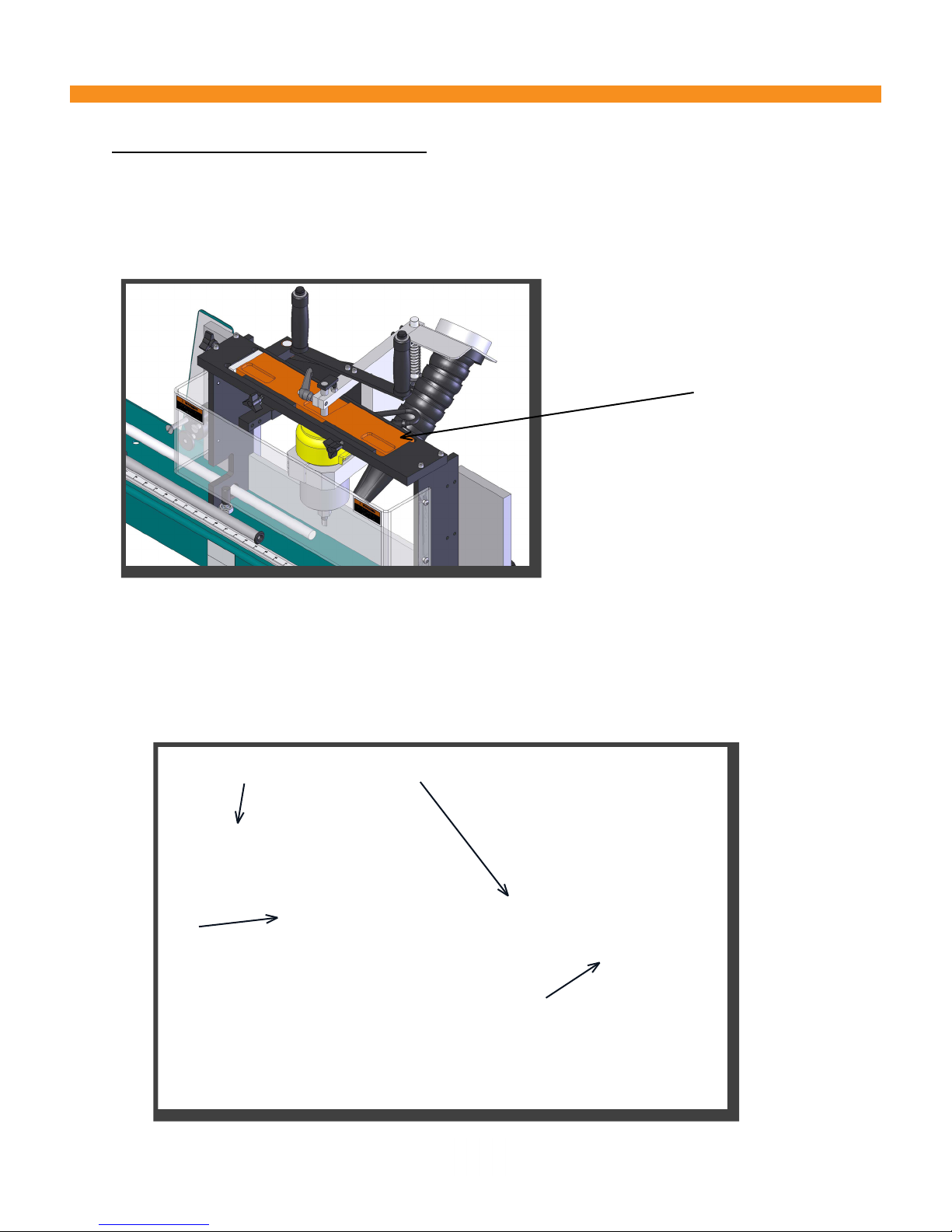
The 250MX is designed to use “multi-feature” templates which allows for the machining of regular and
deadbolt strike plates without unclamping and repositioning the jamb. Two knobs, located on the front
of the template holder, allow for changing templates without the need of tools. Note the shims that are
between the template and the template holder - they are required to insure correct locating and clamping
of the template.
Fig. 3-1

16
ADJUSTMENTS
3-2 BOLT RELIEF:
The center of the bolt relief in the jamb should be a distance in from the leading edge of the jamb equal
to half the width of the door. For example, for a 1-3/8” thick door, the center of the bolt relief would be
11/16” from the edge of the jam.
The two stop assemblies, located on each side of the router assembly, provide adjustment for centering
the bolt relief. Use the large round “buon” for interior jambs, the short machine screw for exterior jambs
and the long machine screw for other applications that might require a third stop.
(REFER TO FIGURE 3-2, PAGE 15)
The adjustable stop assemblies at each end of the machine reference the jamb for correct strike plate
height. On the stop turret, the “buon” opposite the pivot shaft is used for interior jambs and either one
or both of the other “buons” are used for exterior jambs.
To adjust for strike plate height:
1. Lay out the position of the full lip strike plate on a interior jamb (be sure to allow for header clear-
ance).
2. Clamp the jamb and test rout until the jamb is in the proper position.
3. Align the indicator buon on the end of the stop slide rod with the appropriate reading on the scale
(ie. 44”) and secure the rod in place by tightening the locking lever.
4. Loosen and move the appropriate stop “buon” (buon opposite the pivot shaft) to the dado on the
header end of the jamb (top) and secure it with the jamb nut.
5. Repeat the process using an exterior jamb and one of the other stop “buons”.
3-2 STRIKE PLATE HEIGHT:
STOP ASSEMBLY
FOR BOLT RELIEF
Fig. 3-3
17
ADJUSTMENTS
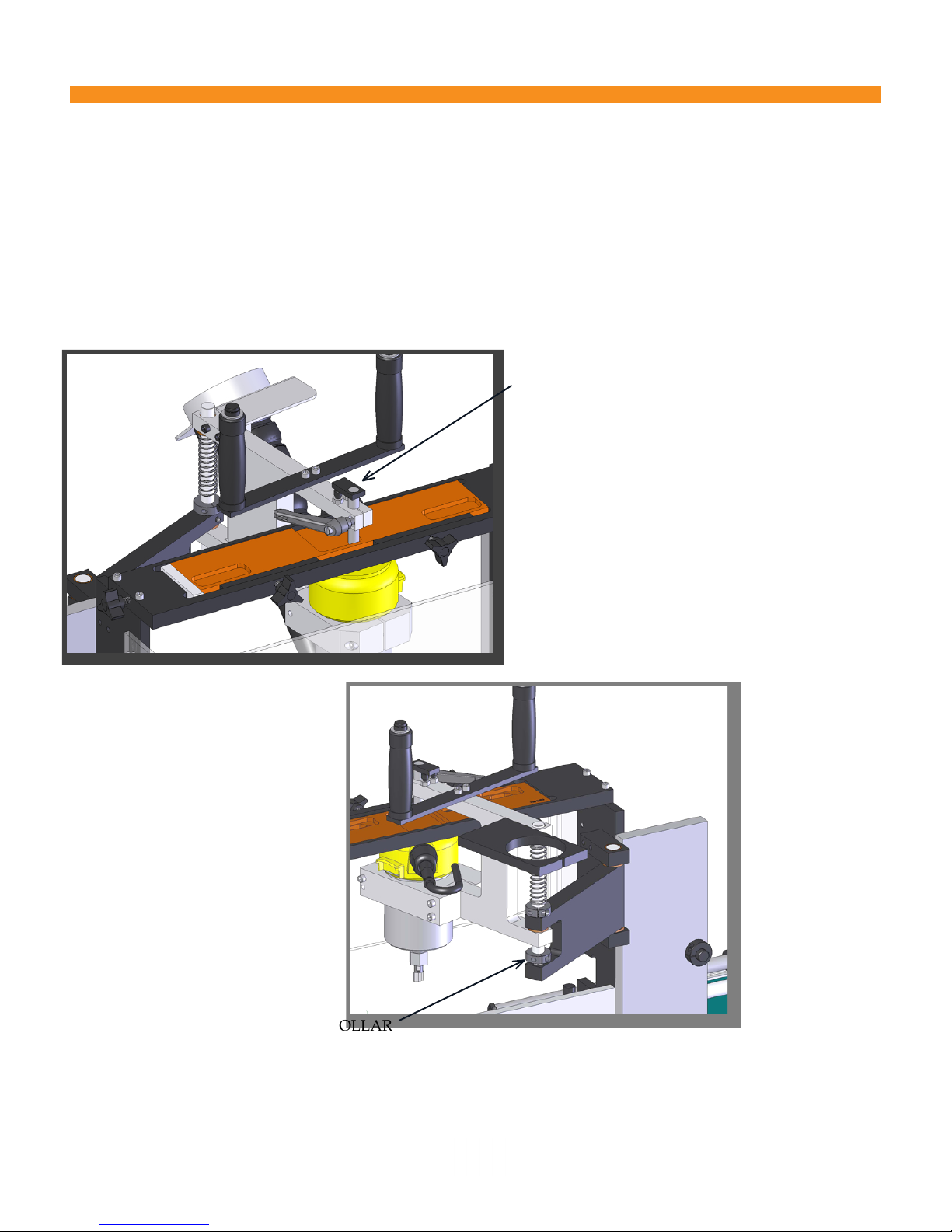
3-3 FACEPLATE MORTISE AND BOLT RELIEF DEPTH:
The depth of the faceplate mortise is controlled using the template follower. Start by making sure that the router bit
shank is seated all the way in the router collet and the router motor is all the way “down” in the clamp. Adjust for cor-
rect mortise depth by changing the eective length of the template follower. Make sure that the follower is high enough
though so the router can be moved from feature to feature. The tab on the top of the follower along with the two adjust-
ment screws allows you to change between two pre-set depths.
Bolt relief (pocket) depth is determined by the position of the lower shaft collar on the hinge rod. The lower the shaft col-
lar, the deeper the bolt relief. The relief should be of sucient depth to allow the latch bolt to come to the end of its travel
Fig. 3-4b
LOWER SHAFT COLLAR
TEMPLATE FOLLOWER
Fig. 3-4a

18
3-4 SINGLE FEATURE TEMPLATES:
The 250MX is equipped with an auxiliary set of end stops for use when single feature (250M) templates
are used for deadbolt mortising. They are adjusted in the same way as are the standard stops (refer to
section 3-2). The stops pivot, so when not in use they can be rotated out of the way.
Fig. 3-6
3-5 AUXILIARY STOPS:
The 250MX is shipped with an auxiliary set of spacers (in the Boxed Parts with the router wrenches and
Owners Manual) that are used to correctly locate single feature 250M style templates. The shorter spacer
with the index pin goes on the right hand side, the plain spacer on the left.
PLAIN SPACER - 4-3/4” LONG
(0232-030)
SPACER WITH INDEX PIN
(0232-113)
Fig. 3-5

19
MAINTENANCE
SECTION 4 MAINTENANCE
4-1 GENERAL MAINTENANCE
It is the machine owner’s responsibility to insure that the machine is properly maintained and that per-
sonnel are adequately trained to safely perform the maintenance function.
A program of routine and preventive maintenance that is strictly adhered to will keep expensive “down
time” to a minimum and give maximum life to the machine. Please read and use the following checklist
for daily and weekly procedures.
ALWAYS LOCK AND TAG OUT THE ELECTRICAL AND PNEUMATIC
POWER SOURCES TO THE MACHINE BEFORE STARTING INSPECTION
OR PERFORMING MAINTENANCE.
4-2 DAILY CHECKS: (EVERY 6-8 HOURS OF OPERATION)
1. Inspect the machine for loose fasteners. Check the pneumatic system for leaking ings or tubing or
kinked tubing.
2. Clean the entire machine with an air hose.
3. Run a test jamb to insure that all adjustments are accurate.
4-3 WEEKLY CHECK: (EVERY 30-40 HOURS OF OPERATION)
1. Clean all moving parts on the router assembly with a not-ammable, non-oil based cleaning solvent
to remove any pitch build-up.
4-4 GENERAL MAINTENANCE COMMENTS
A clean machine is essential for superior performance and reduced maintenance.
As the seals in valves and cylinders will take a “set” when not operating, the manufacturers of those
components strongly recommend that the valves and cylinders be cycled at least twice before starting the
days work. This pre-cycling allows the seals to retain natural sealing ability and will lengthen the life of
the valves and cylinders considerably.
Never use oil, silicon or graphite to lubricate any bearing surface or chrome slide rod. Any lubricants
such as those mentioned above will collect ne sawdust and dirt particles that will wear the bearings very
quickly. If any assembly is binding and you have kept everything clean, the problem is most likely that
the parts are not properly aligned or have become excessively worn.
Clean, dry air is a must. Moisture or solid contaminants in the air supply will shorten the life of air com-
ponents considerably. We recommend you make it a common practice to inspect your compressor and air
system regularly. Drain the compressor tank and all moisture traps daily. Keep the compressor’s crank-
case full and change the oil at thee recommended intervals.
Maintain an adequate air supply to the machine. Regulator pressure should not drop during operation.
If it does, check the condition of the lters. Clean or replace them as required.

20
PARTS AND ASSEMBLY SCHEMATICS
TABLE OF CONTENTS
Main Assembly
Router Assembly
Frame & End Stops
Electrical Enclosure
Ball Catch Stops (Optional)
Material Rack Assembly (Optional)
21
22
23
24
25
26
ASSEMBLY SCHEMATICS
Table of contents
Other Norfield Power Tools manuals


Popular Power Tools manuals by other brands

Ferm Industrial
Ferm Industrial HAM1017P Original instructions

Bridgeport
Bridgeport Hardinge 1 Series Installation operation & maintenance

Dremel
Dremel 400 SERIES DIGITAL 398-49 Operating/safety instructions

Makita
Makita DJS161 instruction manual

Ryobi
Ryobi JS451L Repair sheet

Bosch
Bosch GOP 30-28 Professional Original instructions

Milwaukee
Milwaukee 6514 Series Operator's manual

Rowley
Rowley NS10 & NS11 Safety, operation and maintenance instructions

Makita
Makita DJS200 instruction manual

POWER ON BOARD
POWER ON BOARD VEC280POB User's manual & warranty information

Idex
Idex BAND-IT CP4000-D operating instructions

NovoPress
NovoPress SB 203 operating manual


