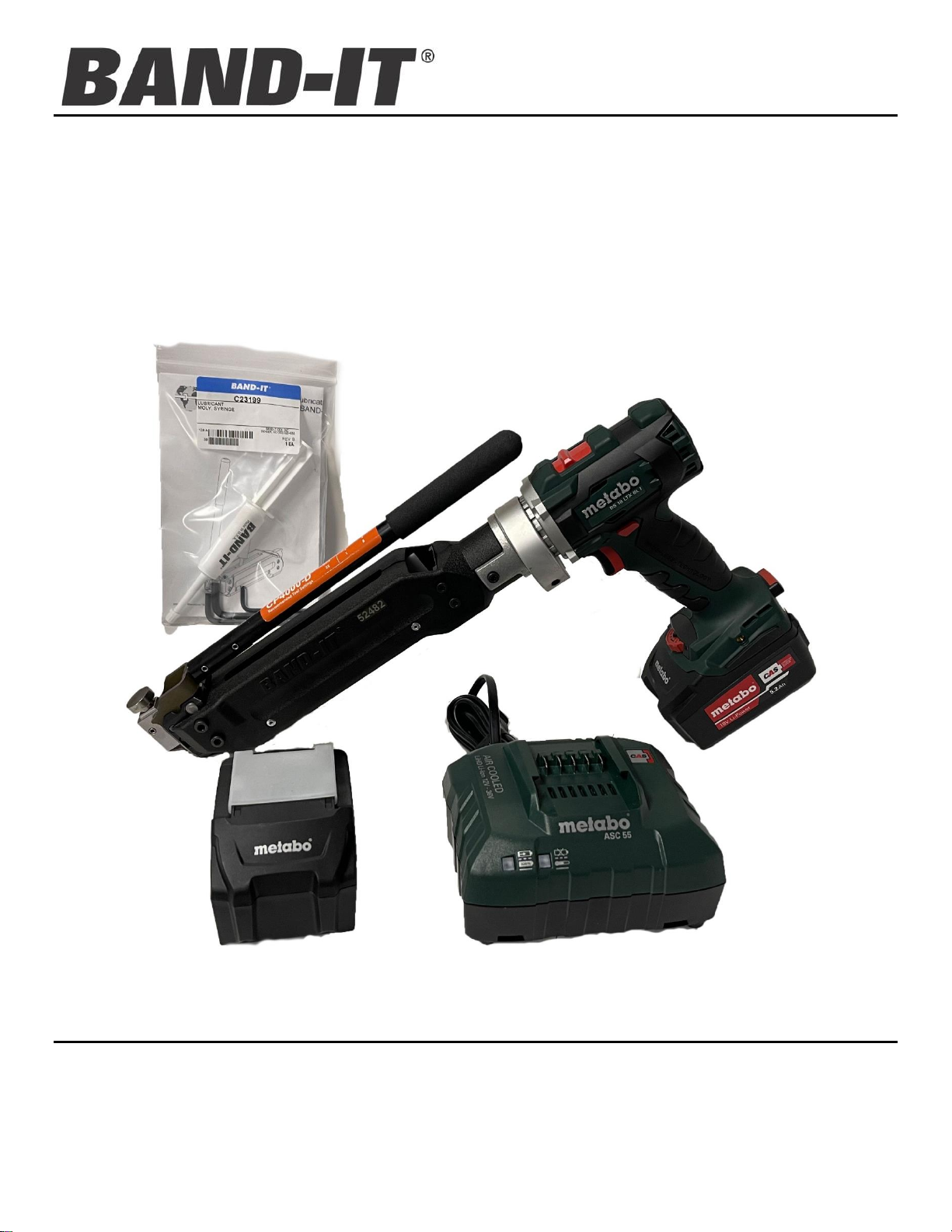
Idex BAND-IT CP4000-D User manual

CP4000-D
CENTER PUNCH TOOL
BAND-IT IDEX, Inc. Document # P50986 Rev.A
A Unit of IDEX Corporation © Copyright
4799 Dahlia Street www.BAND-IT-IDEX.com BAND-IT IDEX, Inc. 2021
Denver, CO 80216-0307 USA All Rights Reserved
P: 1-800-525-0758
F: 1-800-624-3925 1
Operating Instructions
Cordless Center Punch Tool

CP4000-D
CENTER PUNCH TOOL
BAND-IT IDEX, Inc. Document # P50986 Rev.A
A Unit of IDEX Corporation © Copyright
4799 Dahlia Street www.BAND-IT-IDEX.com BAND-IT IDEX, Inc. 2021
Denver, CO 80216-0307 USA All Rights Reserved
P: 1-800-525-0758
F: 1-800-624-3925 2
Contents
Warranty and Safety Guidelines....................................................................................................3
Setup Instructions..........................................................................................................................4
Tool Settings..................................................................................................................................6
Parts List........................................................................................................................................7
Exploded View...............................................................................................................................8
Clamp Application: Center Punch Clamps...................................................................................11
Clamp Inspection.........................................................................................................................12
Maintenance................................................................................................................................14

CP4000-D
CENTER PUNCH TOOL
BAND-IT IDEX, Inc. Document # P50986 Rev.A
A Unit of IDEX Corporation © Copyright
4799 Dahlia Street www.BAND-IT-IDEX.com BAND-IT IDEX, Inc. 2021
Denver, CO 80216-0307 USA All Rights Reserved
P: 1-800-525-0758
F: 1-800-624-3925 3
Warranty and Safety Guidelines
WARRANTY
Refer to website for warranty information: http://www.band-it-idex.com/warranty.html
NOTE: Any performance data published herein is based on laboratory tests, which cannot duplicate conditions that
may be encountered in field installations. Such conditions may vary results substantially from those shown (such as
abuse in handling and installation, failure to follow recommended handling and installation practices, abnormal
environmental conditions, disregard of operating instructions for BAND-IT tools or non-recommended combinations of
BAND-IT products). BAND-IT cannot be responsible for performance characteristics from such variables.
Safety Guidelines
WARNING:
Always wear safety glasses when operating this tool and keep both hands and clothing away from clamp
being tensioned. Squeezing force can reach as high as 2 tons. Never attempt to clamp objects which can
shatter or otherwise cause bodily harm. Tensioning the clamp can be stopped immediately by releasing the
trigger. Detailed instructions are in this manual and the operator is advised to read it and become familiar with
operating the tool.
IMPORTANT FOR HOSE APPLICATIONS:
•When clamping a hose end, remember that a tighter clamp keeps the fitting more secure, but excess
tension can damage the hose. A fitting stem must have prominent barbs for proper retention inside
the hose, but must not be sharp to prevent cutting into the hose. Hose, fitting, and clamp must be
compatible with each other and the environment used in. If in doubt, consult the hose or fitting
manufacturer or call BAND-IT.
•Improperly tightened clamps may result in dangerous hose assemblies, which could cause injuries or property
damage.
•Abuse or use of a hose outside the manufacturers recommended conditions may cause it to quickly deteriorate
and become a safety hazard. This could result in serious injury or property damage. Inspect and test hose
assemblies frequently.
Clamping objects other than hose requires similar precautions.
Use only with BAND-IT 5/8” GCS and 201 SS Preformed Clamps
Use of Alternate Drills
CAUTION!
This tool is designed to work solely mounted to the Metabo BS 18 LTX series cordless drill. Use of any other drills in
place of these Metabo BS 18 LTX drills may result in unsatisfactory performance, hazards to the operator and/or the
tool, or unsafe clamps. Disregard of this caution voids the warranty of the tool and releases BAND-IT of any and all
liabilities arising from such misuses.

CP4000-D
CENTER PUNCH TOOL
BAND-IT IDEX, Inc. Document # P50986 Rev.A
A Unit of IDEX Corporation © Copyright
4799 Dahlia Street www.BAND-IT-IDEX.com BAND-IT IDEX, Inc. 2021
Denver, CO 80216-0307 USA All Rights Reserved
P: 1-800-525-0758
F: 1-800-624-3925 4
Setup Instructions
1. Read safety instructions and operator’s manual for the Metabo BS 18 LTX cordless Drill. Check to make sure
drill is properly set up for use with Band-It Center Punch Tool as follows:
a. Drill spindle has a Clutch Assembly (Band-It # UL4001)
b. See page 6 for recommended Drill speed and torque settings.
2. Charge Drill Battery according to the operator’s manual.
3. To mount the Drill onto the Band-It Center Punch Tool:
a. First, using the two #10-32 x 3/8" screws (M06187), tighten the Tool Body Adapter (M07697) on the
Tension Tool (CP0001) with 20–30 in-lbs.
b. Place the Adapter Collar (M08288) over the Tool Body Adapter.
c. Orient the Drill Clutch Pin (M07187) horizontally (see page, 5 Figure 2).
d. Carefully place the Tool Body Adapter over the Drill’s collar. If there is any additional resistance, gently
rotate the Tension Tool until the Tension Screw engages with the Drill Clutch (M04298) (see page 5,
Figure 3), and rotate Tension Tool to the desired orientation.
e. Position Tool Body Adapter to butt-up against the shoulder of the drill.
f. Slide the Adapter Collar against this shoulder and fasten to 40–60 in-lbs.
4. This tool was designed for and can only be used with BAND-IT 5/8” Center Punch Clamps. Do not attempt to
use on any other type of clamp style.
Figure 1

CP4000-D
CENTER PUNCH TOOL
BAND-IT IDEX, Inc. Document # P50986 Rev.A
A Unit of IDEX Corporation © Copyright
4799 Dahlia Street www.BAND-IT-IDEX.com BAND-IT IDEX, Inc. 2021
Denver, CO 80216-0307 USA All Rights Reserved
P: 1-800-525-0758
F: 1-800-624-3925 5
Drill Clutch M04298
Note: Tool Body Adapter and Adapter Collar are hidden for clarity
Tension Screw M00987
CP Tool Body
NOTE: Alignment is critical for proper tool function.
Orient Drill Clutch
Pin M07187
horizontally
Figure 2: Align the pin within the drill clutch
Figure 3: Align the end of the Tension Screw with the slot in
the end of the Drill Clutch during assembly, as shown above.

CP4000-D
CENTER PUNCH TOOL
BAND-IT IDEX, Inc. Document # P50986 Rev.A
A Unit of IDEX Corporation © Copyright
4799 Dahlia Street www.BAND-IT-IDEX.com BAND-IT IDEX, Inc. 2021
Denver, CO 80216-0307 USA All Rights Reserved
P: 1-800-525-0758
F: 1-800-624-3925 6
Tool Settings
Recommended Drill Torque Dial Settings:
Drill Model: Metabo BS 18 LTX
Clamp Material
Speed
Clutch
GCS
1
4
201 SS
1
7
Band-It recommends hearing protection if this setting is used for an extended time.
NOTE: These torque settings are suggested settings only; individual tools should be adjusted for the
clamping application. Inspect lock per instructions on page 9-11.
Battery Recommendation: In order to maintain consistent tension when installing clamps, Band-It recommends
that the drill be recharged once the indicator on the battery drops to 1 out of 4.
Important: Changing speed and clutch settings will alter tension output. Drill Trigger should be depressed fully
by the operator to attain correct, and consistent, tension when installing clamps. Tension output may vary from
tool to tool, at the same setting, depending on condition and wear of internal components.
Caution: Improperly tightened clamps may result in dangerous assemblies, which could cause injuries or
property damage.
Using correctly sized clamps (diameter) will, in most cases, eliminate the need to pull on clamp tail more than
once. Tension Block moves approximately 5". On occasion, if needed, large size clamps can be installed by
taking several bites (clamp tail feeds out through back of tool). Position of Tension Block, containing gripper,
can be monitored through viewing slot just under cut-off handle. The tool features a built-in disengaging
mechanism to prevent tension screw from jamming up. At the end of the Tension Block travel the safety clutch
will engage and the user will hear a ratcheting sound. Excessive use of this feature will wear the Drill Clutch
mechanism and/or Tension Screw out prematurely.

CP4000-D
CENTER PUNCH TOOL
BAND-IT IDEX, Inc. Document # P50986 Rev.A
A Unit of IDEX Corporation © Copyright
4799 Dahlia Street www.BAND-IT-IDEX.com BAND-IT IDEX, Inc. 2021
Denver, CO 80216-0307 USA All Rights Reserved
P: 1-800-525-0758
F: 1-800-624-3925 7
Parts List
ITEM NO.
PART NUMBER
QTY
DESCRIPTION
1
A33887
1
SPR, COMP, .18 DIA X .813L
2
A53587
2
SPR, COMP, .30 DIA X 1.0, #20.5
3
C23199
-
LUBRICANT, MOLY, SYRINGE
4
I16387*
-
LUBRICANT, SUPER LUBE W/ TEFLON
5
J64387
1
PIN, SPRING, .187D X .625L
6
J67287
4
SCREW, CAP, 1/4-28 X .50 L
7
M00987
1
TENSION SCREW
8
M01388
1
PIN, .187 DIA X 1.50 LONG
9
M01487
1
PIN, DOWEL, 1/4D X 1.5L
10
M01787
1
PLATE, BACK
11
M02187
1
CUTTER BLADE, CP
12
M02287
1
TIP, LOAD BEARING
13
M02587
2
SCREW, CAP, 1/4-28 X .75 L
14
M02687
1
CUTTER KNIFE, CP
15
M02887
1
TOOL HEAD, CP
16
M02987
1
SLOT PLATE, CP
17
M03087
1
CAM, CUT-OFF, CP
18
M03287
2
ROLLER, CUT-OFF
19
M04187
1
PUNCH HOLDER, CP
20
M04287
1
PUNCH ARM, CP
21
M04387
1
TRIPPER BRACKET
22
UL1219
1
HANDLE ASSEMBLY:
INCLUDES HANDLE, HANDLE GRIP, AND PINS
24
M06187
4
SCREW, CAP, #10-32 X .375 L
25
M06587
1
BALL, 1/4" DIAMETER
26
M07387
1
BODY, LEFT
27
M07487
1
BODY, RIGHT
28
M07587
2
WEAR PLATE
29
M07987
2
THREADED INSERT, #10-32
30
M08087
4
RIVET, BLIND, .125 X .328 LONG
31
M08187
4
WASHER, .128 ID X .238 OD
32
M08887
1
GRIPPER
33
M09087
1
TENSION BLOCK
34
M09187
1
GRIPPER GUIDE
35
M05387
1
BEARING TIP
36
M88787
1
PIN, CLEVIS, 1/4 X 1-1/4
38
T32190**
1
PUNCH REPAIR KIT
INCLUDES RETAINING BALL AND PUNCH
Notes:
Apply Item 4 (Super Lube) to:
Item 3 (Cutter Knife) at contact
point with item 15 (Tool Head) and
item 18 (Rollers)
Inside slot profile of item 33 (Tension
Block)
Apply Item 3 (Grease) to:
Item 7 (Tension Screw) threads
and grooved end
Item 11 (Cutter Blade) counter-bore
only, after item 35 (Bearing Tip)
has been installed.
Tighten the following:
Item 6 (1/4-28 X .5 Screws)
to 90 –110 in-lbs.
Item 13 (1/4-28 X .75 Screws)
to 90 –110 in-lbs.
Item 24 (#10-32 Screws)
to 60 –70 in-lbs.
* Permatex P/N: 82325 or Equivalent
**T32190 Punch Repair Kit includes a
punch holder that is not compatible
with CP4000-D. Do not use.

CP4000-D
CENTER PUNCH TOOL
BAND-IT IDEX, Inc. Document # P50986 Rev.A
A Unit of IDEX Corporation © Copyright
4799 Dahlia Street www.BAND-IT-IDEX.com BAND-IT IDEX, Inc. 2021
Denver, CO 80216-0307 USA All Rights Reserved
P: 1-800-525-0758
F: 1-800-624-3925 8
Exploded View
Figure 4

CP4000-D
CENTER PUNCH TOOL
BAND-IT IDEX, Inc. Document # P50986 Rev.A
A Unit of IDEX Corporation © Copyright
4799 Dahlia Street www.BAND-IT-IDEX.com BAND-IT IDEX, Inc. 2021
Denver, CO 80216-0307 USA All Rights Reserved
P: 1-800-525-0758
F: 1-800-624-3925 9
Tension Gripper Assembly
Figure 5

CP4000-D
CENTER PUNCH TOOL
BAND-IT IDEX, Inc. Document # P50986 Rev.A
A Unit of IDEX Corporation © Copyright
4799 Dahlia Street www.BAND-IT-IDEX.com BAND-IT IDEX, Inc. 2021
Denver, CO 80216-0307 USA All Rights Reserved
P: 1-800-525-0758
F: 1-800-624-3925 10
Tool Head Assembly
Figure 6

CP4000-D
CENTER PUNCH TOOL
BAND-IT IDEX, Inc. Document # P50986 Rev.A
A Unit of IDEX Corporation © Copyright
4799 Dahlia Street www.BAND-IT-IDEX.com BAND-IT IDEX, Inc. 2021
Denver, CO 80216-0307 USA All Rights Reserved
P: 1-800-525-0758
F: 1-800-624-3925 11
Clamp Application: Center Punch Clamps
1. Position the clamp on the
object you are clamping.
4. Secure buckle by hitting head
of punch holder 3-5 times
with a hammer or mallet.
2. Actuate drill until tension
block is all the way forward
against the tool body. Insert
clamp tail into tool head slot.
Set drill to clockwise rotation.
6. Reverse drill and feed clamp
tail out of tool.
3. Actuate drill until drill’s built-in
clutch disengages. If tension
block comes near its end of
travel, release actuator switch
and reverse drill to pull more
on clamp tail. Excessive use
of disengaging drill clutch
indicated by loud ratcheting
sound leads to premature
wear of tension screw.
5. Pull the cut-off handle forward
to cut off tail, then return
handle to the down position.

CP4000-D
CENTER PUNCH TOOL
BAND-IT IDEX, Inc. Document # P50986 Rev.A
A Unit of IDEX Corporation © Copyright
4799 Dahlia Street www.BAND-IT-IDEX.com BAND-IT IDEX, Inc. 2021
Denver, CO 80216-0307 USA All Rights Reserved
P: 1-800-525-0758
F: 1-800-624-3925 12
Clamp Inspection
Good Clamp
Outer band remains
flush with inner band
Inspect buckle on the completed clamp.
Important: Visually inspect lock formed in band as shown. If the top band has slipped out from the punched
buckle, remove clamp and install a new one. A bad clamp may indicate that the punch was not deep enough to
secure the band in place.
NOTE FOR HOSE APPLICATIONS:
When applying clamps on soft, thick-walled hose, tension clamp then wait a full 30 seconds.
Clamps may be re-tensioned by squeezing the Drill Trigger on the power unit a second time prior to
forming the lock and cutting the excess clamp tail. This allows hose to “settle” under the band of
the clamp. This hose material attribute is called Cold Flow.
Bad Clamp
Figure 7
Outer band slides out of buckle and
creates gap between inner band
Cut end
Cut end

CP4000-D
CENTER PUNCH TOOL
BAND-IT IDEX, Inc. Document # P50986 Rev.A
A Unit of IDEX Corporation © Copyright
4799 Dahlia Street www.BAND-IT-IDEX.com BAND-IT IDEX, Inc. 2021
Denver, CO 80216-0307 USA All Rights Reserved
P: 1-800-525-0758
F: 1-800-624-3925 13
Trouble-Shooting
1. Outer band slides out of buckle after installation: Inspect dimple depth created by punch.
If not adequate, increase hammer force applied to punch.
2. Drill clutch releases prematurely: Make sure Tool is fully seated on Drill (per page 4). If
problem persists, contact BAND-IT technical support.
3. If tool does not cut off tail:
a. Check the torque wheel to make sure it is on the recommended setting.
b. Inspect Gripper for wear or debris, which can impact the tool’s ability to achieve the
required tension for cut-off. See page 15 for instructions on how to access the gripper
for cleaning or replacement.
c. Inspect the slot plate for wear. Excessive wear may allow the clamp buckle to interfere
with cut-off. In this case, the Slot Plate will need to be replaced.
4. Tool does not fully tension clamp: Check gripper assembly and tension screw for
excessive dirt/grime build up. Lubricate tension screw if needed (see page 14).
Note: To mitigate Drill Clutch wear, do not over-use the Drill Clutch. When tensioning a clamp,
let the Drill Switch go as Tension Block nears its end of travel. Reverse drill and send Tension
Block all the way forward for a second pull on the band.

CP4000-D
CENTER PUNCH TOOL
BAND-IT IDEX, Inc. Document # P50986 Rev.A
A Unit of IDEX Corporation © Copyright
4799 Dahlia Street www.BAND-IT-IDEX.com BAND-IT IDEX, Inc. 2021
Denver, CO 80216-0307 USA All Rights Reserved
P: 1-800-525-0758
F: 1-800-624-3925 14
Maintenance
1. Approximately every 500 clamps lubricate Tension Screw
with molybdenum disulfide lubricant or equivalent. Make
sure the Tension Block is all the way forward against the
Tool Head. Remove cap from syringe and insert tip of
syringe into slot on top of tool body. Press the tip against
the Tension Screw just behind the Tension Block and
squeeze out approximately 1/2" long bead of lubricant.
Remove Syringe and actuate tool without a clamp a
couple of times to spread lubricant evenly on tension
screw. To order more lubricant, specify BAND-IT
#C23199
2. Every 500-1000 clamps, depending on torque setting,
inspect and repack front bearing with same lubricant.
Turn load bearing tip and small bearing tip over for a new
bearing surface.
Bearing Detail
3. To gain access to bearing components: First, back off Tension Block if flush with Tool Head. Then remove Tool
Head Mounting Screws (4 places). Tool Head Assembly should now pull free from Tool Body. Use a paper clip or
other thin object to push bearing components out of Blade. Wipe lubricant from components. If ball or bearing tips
appears heavily worn, replace with new one. Note: 1/4" ball is made from hard tungsten carbide material, do not
replace with regular ball bearing. (Smooth indention from ball in the bearing tips is normal).
4. To re-assemble bearing components: wipe blade cavity clean. Push small bearing tip into blade cavity. Apply
lubricant to ball and push into Blade cavity and fill remaining space with lubricant. Push load bearing tip firmly into
blade cavity, some lubricant will be squeezed out. Re-attach Tool Head to Tool Body, making sure that load bearing
tip extends into Tension Screw.
Figure 9
Figure 8

CP4000-D
CENTER PUNCH TOOL
BAND-IT IDEX, Inc. Document # P50986 Rev.A
A Unit of IDEX Corporation © Copyright
4799 Dahlia Street www.BAND-IT-IDEX.com BAND-IT IDEX, Inc. 2021
Denver, CO 80216-0307 USA All Rights Reserved
P: 1-800-525-0758
F: 1-800-624-3925 15
Tension
Screw
M00987
Move tension
block all the way
forward against
the tool head
Tool Head
M02887
Gripper
M08887
Screw, #10-32
M06187
Figure 10
5. To Replace Gripper: Make sure Tension Block is all the way forward against the tool head. Remove drill.
Remove tool adapter body. Remove one side of the tool body or the other, not both. Slide Gripper out sideways
and replace with a new one. Re-attach Tool Body side. Caution: Do not push or move Tension Block while
Gripper is out of tool.
6. To Replace Tension Screw: Move Tension Block all the way back (away from Tool Head) using drill in tensioning
mode (clockwise). Remove Center Punch Tool from Drill. Remove the Tool Adapter from the tool. Remove Blade
and load bearing tip from Tensioning Screw (see bearing detail). Remove one side of the Tool Body or the other,
not both. Grasp the smooth barrel on Tension Screw and pull all the way forward until Tension Block is against the
Tool Head. If Tension Screw is stuck, use a punch and tap the center of the screw from the back end of the tool.
Turn Tension Screw out of Tension Block. Lubricate new Tension Screw with Molybdenum Disulfide lubricant, or
equivalent. Install new Tension Screw in reverse order; making sure that back end of Tension Screw extends well
beyond the back end of the Tension Block. Push the assembly all the way back and extend the round portion of
the Tension Screw through holes on the tripper bracket and back guide plate. Reinstall Tool Body side. Reinstall
Blade and tighten the Blade Mounting Screws approximately 120 in-lbs. Reattach Tool Adapter to Center Punch
Tool. Reattach Tool to Drill and drive Tension Block all the way forward.

CP4000-D
CENTER PUNCH TOOL
BAND-IT IDEX, Inc. Document # P50986 Rev.A
A Unit of IDEX Corporation © Copyright
4799 Dahlia Street www.BAND-IT-IDEX.com BAND-IT IDEX, Inc. 2021
Denver, CO 80216-0307 USA All Rights Reserved
P: 1-800-525-0758
F: 1-800-624-3925 16
7. To Replace Punch: Back off Tension Block if flush with Tool Head. Remove Tool Head Mounting Screws (4
places). Tool Head Assembly should now pull free from Tool Body. Slide clevis pin out from Tool Head to release
Punch Assembly. Press out spring pin so that Punch Holder can be removed from Punch Arm. Remove retaining
ball and replace punch. To reassemble, repeat these steps in reverse order.
Figure 11
Punch Holder
M04187
Retaining Ball
and Punch
Kit# T32190
Punch Arm
M04287

CP4000-D
CENTER PUNCH TOOL
BAND-IT IDEX, Inc. Document # P50986 Rev.A
A Unit of IDEX Corporation © Copyright
4799 Dahlia Street www.BAND-IT-IDEX.com BAND-IT IDEX, Inc. 2021
Denver, CO 80216-0307 USA All Rights Reserved
P: 1-800-525-0758
F: 1-800-624-3925 17
8. To Replace Knife, Blade or Slot Plate: Remove Tool Head following same steps to replace Punch. Slide ¼”
dowel pin out from Tool Head and remove Cut-off Handle/Cam subassembly. Remove both ¼” socket head
screws. Blade, Slot Plate and Spring can now be removed. To remove Knife, slide 3/16” pin out from Tool Head to
free Knife and Cut-off Rollers. When reassembling, Knife, Rollers and 3/16” pin must be assembled before
installing spring, Slot Plate and Blade. After reassembling, tighten ¼” socket screws to 90-110 in-lbs.
Note: Drills needing repair must be returned to Band-It.
Figure 12
Retaining Ball
and Punch
Kit# T32190
¼” Socket
Screws
Table of contents
Popular Power Tools manuals by other brands

Jet
Jet TPFA-X Operating instructions and parts manual

EINHELL
EINHELL E-PST operating instructions

Shop fox
Shop fox SHOP FOX W1764 owner's manual

Baileigh Industrial
Baileigh Industrial MSS-14F Operator's manual

Clarke
Clarke CTIDG2 Operation & maintenance instructions

Electronica Technologies
Electronica Technologies EL400 manual