Norfield 1020 User manual

1
1020/1020K DOUBLE END TRIM SAW
PRODUCTAND OPERATIONS MANUAL
DOCUMENT NUMBER 17-245
Eff. S/N TS-1902
Rev 6
Release 0

2
Norfield Industries
P.O. Box 459
Chico, CA 95927
SERVICE: (530) 891-4214 PARTS: (800) 824-6242
Serial No:
Date Sold:
Norfield Industries is the name that represents Quality, Reliability, Support, Innovation and
True Customer Service. We have been dedicated to providing quality products and excellent
customer service for more than 40 years. Norfield Industries has earned a reputation in the
pre-hanging industry for setting standards for reliable machinery, full technical support,
machine parts, full line industrial woodworking tools and supplies and a team of customer
care representatives to support you! Our factory-trained technical personnel are ready to
assist you on the telephone or in your shop.

3
TABLE OF CONTENTS
TABLE OF CONTENTS..............................................................................................................................3
INTRODUCTION ........................................................................................................................................6
SAFETY INFORMATION...........................................................................................................................7
SPECIFICATIONS ....................................................................................................................................10
INSTALLATION........................................................................................................................................ 11
1.1 SHIPPING DAMAGE AND SHORTAGES............................................................................................11
1.2 INSTALLATION ....................................................................................................................................11
1.3 POSITIONING THE 1020 DOUBLE END TRIM SAW ........................................................................11
1.4 LEVELING .............................................................................................................................................12
1.5 ELECTRICAL ........................................................................................................................................12
1.6 AIR SUPPLY AND CONNECTION.......................................................................................................13
1.7 REGULATOR SETTING AND TYPE OF OIL .....................................................................................13
1.8 DUST COLLECTOR (OPTIONAL).......................................................................................................13
1.9 BASIC INSTALLATION ADJUSTMENTS...........................................................................................14
1.10 MAJOR COMPONENTS AND CONTROLS.......................................................................................16
OPERATIONAL SETTINGS..................................................................................................................... 17
2.1 QUICK-START GUIDE .........................................................................................................................17
2.2 SETTING THE MACHINE TO DO MITER CUTS OR END CUTS ....................................................19
2.3 SETTING UP TO CUT DIFFERENT LENGTHS OF MATERIAL......................................................19
2.4 SETTING UP TO CUT DIFFERENT WIDTH MATERIALS...............................................................20
2.5 RESETTING THE CRUTCH TIPS FOR DIFFERENT WIDTH MATERIAL.....................................21
2.6 SETTING UP TO CUT MATERIAL OVER 3" WIDE..........................................................................22
2.7 SETTING UP FOR DIFFERENT THICKNESS MATERIAL...............................................................23
2.8 SETTING THE UNDERCUT ANGLE OR SILL BEVEL......................................................................24
2.9 OPERATING THE KERFING UNIT.....................................................................................................24
2.10 RESETTING THE EMERGENCY STOP SWITCH............................................................................25
ADJUSTMENTS ........................................................................................................................................26

4
3.1 ADJUSTING THE MACHINE BACK TO FACTORY SETTINGS......................................................26
3.2 REESTABLISHING THE CENTER-MARK SCRIBE LINE ................................................................29
3.3 ADJUSTING THE SHOCK ABSORBER...............................................................................................31
3.4 ADJUSTMENT OF THE FEED ASSEMBLY STOPS...........................................................................31
3.5 ADJUSTING THE CYCLE RATE OF THE KERFING MOTORS. .....................................................32
3.6 ADJUSTING THE FEED ASSEMBLY CYCLES PER MINUTE .........................................................33
3.7 FEED START AND FEED RETURN PILOT VALVE ADJUSTMENT................................................36
3.8 ADJUSTING HEIGHT OF KERFING BLADES (OPTIONAL EQUIPMENT)....................................37
3.9 JET AIR PULSE ADJUSTMENT...........................................................................................................37
3.10 SAW DRIVE BELT ADJUSTMENT....................................................................................................38
3.11 FEED SYNC ASSEMBLY EQUALIZATION ADJUSTMENT............................................................39
3.12 ADJUSTMENT OF MITER OR SQUARE CUTS................................................................................40
MAINTENANCE........................................................................................................................................ 42
4.1 ROUTINE & PREVENTATIVE MAINTENANCE ...............................................................................42
4.2 DAILY CHECKS: (EVERY 6-8 HOURS OF OPERATION) ................................................................42
4.3 WEEKLY CHECKS: (EVERY 30-40 HOURS OF OPERATION)........................................................42
4.4 MONTHLY CHECKS: (EVERY 100-200 HOURS OF OPERATION) .................................................43
4.5 GENERAL MAINTENANCE COMMENTS..........................................................................................43
4.6 CHANGING THE SAW BLADES..........................................................................................................44
4.7 CHANGING THE KERFING BLADES (OPTIONAL EQUIPMENT)..................................................44
4.8 SAW DRIVE MANDREL REPLACEMENT .........................................................................................45
4.9 SAW DRIVE CYLINDER REPLACEMENT.........................................................................................46
4.10 SAW DRIVE BELT REPLACEMENT.................................................................................................47
TROUBLESHOOTING.............................................................................................................................. 49
5.1 TROUBLE CHECK LIST.......................................................................................................................49
APPENDIX A
ASSEMBLY DRAWINGS ............................................................................................................................52
APPENDIX B

5
SCHEMATICS................................................................................................................................. 73
1020 FLOOR LAYOUT................................................................................................................................77
APPENDIX C ............................................................................................................................................. 78
BASIC PRINCIPLES OF PNEUMATIC PLUMBING................................................................................78

6
INTRODUCTION
Congratulations on your purchase of your Norfield Industries 1020 Double End Trim Saw.
You can be assured that this machine was constructed and assembled to a set of rigid
specifications by trained workers who take pride in the quality of their work. To safely
operate this machine it is vital that you read and understand all safety and operator
instructions.
The Norfield Industries 1020 Double End Trim Saw is designed to quickly and efficiently
process door casings into the appropriate lengths for the door industry. Settings to adjust
length and select miters are quickly made to minimize set-up time. Head or side casings can
be processed with ease using front mounted controls. Undercuts of up to 15 degrees can be
quickly set if needed to match jamb edge profile. An Infeed Hopper allows standard profile
casing to be stacked and fed automatically into the machine. A moveable saw assembly
mirrors a stationary saw and is used to cut, simultaneously, both ends of the casing to the
desired length. Consistent operation at up to 30 pieces a minute can be sustained increasing
the throughput needed for today's high speed machining centers. Add more functionality to
the 1020 with the available Kerfing option.
A safety system including guards, saw-motor brakes, and mechanical/electrical E-stop
functions are designed to provide operator safety.
Prior to shipment from our factory each Norfield machine is put through a series of tests and
inspections to insure that you are provided with the highest quality product for your
business.
In order for this machine to provide you with a long period of continuous and trouble free
service, it is necessary that it be properly installed, operated, and maintained. We urge you
to study the contents of this manual and be guided by the suggestions herein. We strongly
recommend that a periodic review of the contents of this manual be made to maintain a high
level of competency when operating this machine.
I
NTRODUCTION

7
SAFETY INFORMATION
LABEL AND DEFINITIONS
Danger indicates an imminently hazardous situation, which if not
avoided, WILL result in death or serious injury.
Warning indicates a potentially hazardous situation which, if not
avoided, COULD result in death or serious injury.
Caution indicates a potentially hazardous situation which, if not
avoided MAY result in minor or moderate injury. It may also be used
to alert against unsafe practices.
Caution without the safety alert symbol indicates a potentially
hazardous situation which, if not avoided may result in property
damage (i.e. not personal injury).
Notice indicates important information that if not followed may CAUSE
damage to the equipment.
Mandatory Action conveys an action step that should be taken to avoid
the hazard.
I
NTRODUCTION
STOP!
Protect Yourself
This manual contains information that is
important to the safe operation of your
Norfield e
q
ui
p
ment.

8
MUST READ SAFETY INFORMATION!
Read and understand the operator's manual before using this machine. Failure to
follow proper operating instructions could result in death or serious injury.
Do not operate this machine unless all guards are in place and working correctly.
If any guards or hazard labels are missing or damaged call Norfield's Service
department immediately and request a replacement at 800-824-6242.
Only trained personal that have read and understand the operator's manual and all
the safety precautions may operate this machine.
This machine, when in operation, produces wood chips and dust. The operator
and all persons in the work area MUST wear approved eye protection with
permanently attached, rigid plastic side shields. These safety glasses must
conform to ANSI Z87.1 standards and will have "Z87" printed on the lens.
This machine, when in operation, produces a noise level greater than 85dB. The
operator and all persons in the work area MUST wear approved hearing
protection. OSHA has determined that a noise level in excess of 85dB average in
8 hours can cause permanent hearing damage. We recommend that hearing
protection be worn even if the decibel level is below 85dBA.
Certain types of wood dust can cause allergic reactions, Sawdust has been
determined to be a Group Acarcinogen by the International Agency for
Research on Cancer (IARC). A dust collection system or an approved personal
dust mask MUST be used during the operation of this equipment.
This machine has moving parts that loose clothing and long hair can become
entangled in. Take care not to become caught between the work material and the
feed mechanisms or any other moving components.
Inspect the machine at the beginning and end of each shift for damaged or
cracked components such as, but not limited to, saw blades, router bits, drill bits,
and boring bits.
I
NTRODUCTION

9
MUST READ SAFETY INFORMATION! (CONTINUED)
Never leave this machine unattended while it is in operation. Make sure that
all electrical and air is in the off position when the machine is not in use or is
unattended and that any cutting blades have come to a complete stop.
Do not attempt to clean material from this machine until all the cutting blades
have come to a complete stop. Even when the machine has been turned to the
off position it may take up to several minutes for the blades to coast-down to
a complete stop.
Before beginning any service repairs, general maintenance, or adjustments
you MUST follow proper Lockout Tag-Out procedures. OSHA regulation
1910.147 establishes a minimal lockout tag-out procedure to assist employers
in development of their own procedures.
Woodworking machinery is inherently dangerous, common sense and good
safety practices are your best defense against injury.
If you have any questions regarding the correct operation of the machine and
safety procedures in this manual call the Norfield Industries Service
Department at 800-824-6242.
I
NTRODUCTION
10
SPECIFICATIONS
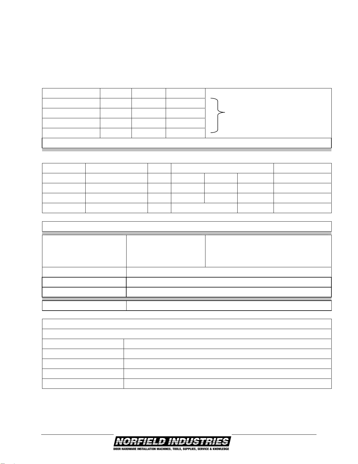
Electrical Requirements:
AC Line Phase Hertz Amperage
Includes Vacuum
208V 3
60HZ 30 A*
230V 3
60HZ 30 A*
460V 3
60HZ 15 A*
575V 3
60HZ 15 A*
*Additional 115V-160HZ 20 Amps With Kerfing Option required
Motor Specifications:
Application Motor HP Amperage Norfield P/N
208V 3230V 3460V 3
Saws BALDOR M3550T l.5 4.3
4.2 2.1 0693-016
Vacuum JET DC1900 3 14.5
14.0 14.0 13-708
Routers DEWALT DW616 1 3/4 11A @120V 15-174
Note: For 575v Motor Specifications See Electrical Schematic
Air Requirements: 22 cfm @ 90 psi
1/2" I.D. Minimum air line when less than
20 feet from compressor OR 3/4" I.D.
minimum air line when more than 20 feet
from compressor
Vacuum Requirements: Min. 1900 cfm - 6" Duct
Approximate Weight: 1600 lbs.
Space requirements: Width 9'6" x Length 18'0"
Machine Capacity Rate: 30 Pieces Per Minute
Machine Capabilities:
1020 & 1020K (CASING & BRICKMOLD)
Length 1 '-6" To 8'-0"
Width TO 3-1/2"
Thickness 3/8" To 1-1/2"
Undercut Angle 0 To 15 Degrees for square end cuts, 0 to 1 degree for miter cuts
Angle Of Cut 90 And 45 Degrees
I
NTRODUCTION

11
SECTION 1
INSTALLATION
1.1 SHIPPING DAMAGE AND SHORTAGES
Before and after the crated machine is unloaded from the truck the create should be
inspected for any signs of damage. If suspected damage is found it must be noted on the bill
of lading and signed by the driver and the person receiving the shipment. After the machine
has been uncrated inspect it and all other contents of the crate for shipping damage. In the
event that damage has occurred in transit notify the freight carrier and Norfield Industries
immediately. Inspect the complete shipment against the packing slip to make sure all items
listed are accounted for. If any shortages are noticed, the freight carrier and Norfield
Industries should be notified immediately. While any shortages, other than back orders, or
freight damages are the complete responsibility of the freight carrier, Norfield Industries
desires to be notified so that the replacement of lost or damaged parts can be expedited.
1.2 INSTALLATION
The information in this chapter refers to the installation and setup of the Norfield 1020
Double End Trim Saw. Since the purchase of the machine includes a startup by a Field
Service Technician, the following six items must be accomplished before the Technician
arrives:
1. Review the pre-installation packet that was sent prior to the shipment of your new
machine.
2. Uncrate the machine and inspect for shipping damage and shortages.
3. Position the machine in its permanent location.
4. Provide the proper electrical supply and make connections.
5. Provide the proper air supply and make connections.
6. Install Lockout/tagout devices on all power sources at the machine.
7. DO NOT TURN ON POWER UNTIL THE SERVICE TECHNICIAN ARRIVES-doing
so may VOID your warranty.
1.3 POSITIONING THE 1020 DOUBLE END TRIM SAW
With the use of a forklift move the machine to its permanent position within your shop.
This space should have been predetermined and power and air must be installed prior to the
Service Technician's arrival.
I
NSTALLATION

12
1.4 LEVELING
It is important to level the machine across the two ends so that there is no twist or strain on
the frame rails. This machine will not function properly if the frame is twisted. It is also
desirable to level the machine from end to end.
1. Place the level down the length of the front frame rail. Level the machine by adjusting
either of the two front leveling feet until the machine is level.
2. Next level the machine across one of its two ends. Place a level across one end of the
frame as shown.
3. Adjust the back leveling foot of the end that you are working on until that end of the
machine is level.
4. Next move the level to the opposite end of the machine and place the level across the
frame as shown.
5. Adjust the back leveling foot of the end that you are working on until that end of the
machine is level.
6. Check the entire machine to make sure that it is level across its entire frame.
1.5 ELECTRICAL
Before connecting any electrical power to the main electrical enclosure, be sure that the
characteristics labeled on the enclosure match those of your service. Refer to the drawing
that was included in the pre-installation packet that was sent prior to this shipment or to the
electrical schematic in Appendix B of this manual.
I
NSTALLATION

13
Clean Dry Air (CDA) is important. Air operated tools and equipment require CDA for top performance
and low maintenance. Foreign material such as dirt, grit and pipe scale generally present in airlines can
cause severe abrasive wear in valves and cylinder walls.
1.6 AIR SUPPLY AND CONNECTION
In order for the machine to perform properly, the quick-disconnect to the machine must be
at least 3/8" inside diameter. Refer to specification section for further information.
A Filter-Regulator-Lubricator (FRL) unit has been installed on your machine to prolong the
life of the machine. The FRL is designed to work with adequate mainline filtration and
drainage (refer to Appendix C). We also recommend the use of an air drying system to
protect all your air tools and equipment.
1.7 FRL SETTINGS AND TYPE OF OIL
Adjust the regulator so that it maintains at least 90 psi during operation of the machine
(100-psi static). For approximately every 33 drops of oil observed at the drip tube in the
sight dome, only one drop of oil will remain in suspension for down stream lubrication,
therefore do not under lubricate. Set the drop-type lubricator so that one drop occurs for
every cycle of the machine. Adjustment of the drip rate is accomplished using a small
screwdriver. Turn the screw, located next to the lubricator filler cap, counterclockwise to
increase drip rate, clockwise to decrease the drip rate. Only use 10WT turbine oil in the
lubricator.
1.8 DUST COLLECTOR (OPTIONAL)
If the dust collection option was purchased with this Norfield 1020 Double End Trim Saw,
or if you wish to connect this machine to an existing in-house dust collector, an 8 inch
diameter hose is required. If the optional dust collector was purchased with this machine
refer to electrical schematic in Appendix B for additional power requirements.
I
NSTALLATION
Regulator Adjustment
Knob 90psi (100 psi
static).
Lubricator filler cap
Sight Dome
14
1.9 BASIC INSTALLATION ADJUSTMENTS
Your new Norfield Industries machine has been carefully
adjusted at the factory prior to shipment, however we
recommend that you check the following initial perimeters to
insure proper operation before running any material through
the machine for the first time.
To check the Magazine width, place a piece of material into the Magazine and hold it
against the Feed Magazine, measure the distance between the material and the Material
Gate; there should be 1/16" to 3/32" clearance. Refer to Section 2 if any adjustment is
required.
To check the Material Gate height clearance. Manually push the material under the gate
opening. Measure the distance from the edge of the gate opening to the thickest part of the
material's profile; this distance should be 1/16" to 1/8" max. Refer to Section 2 if any
adjustment is required.
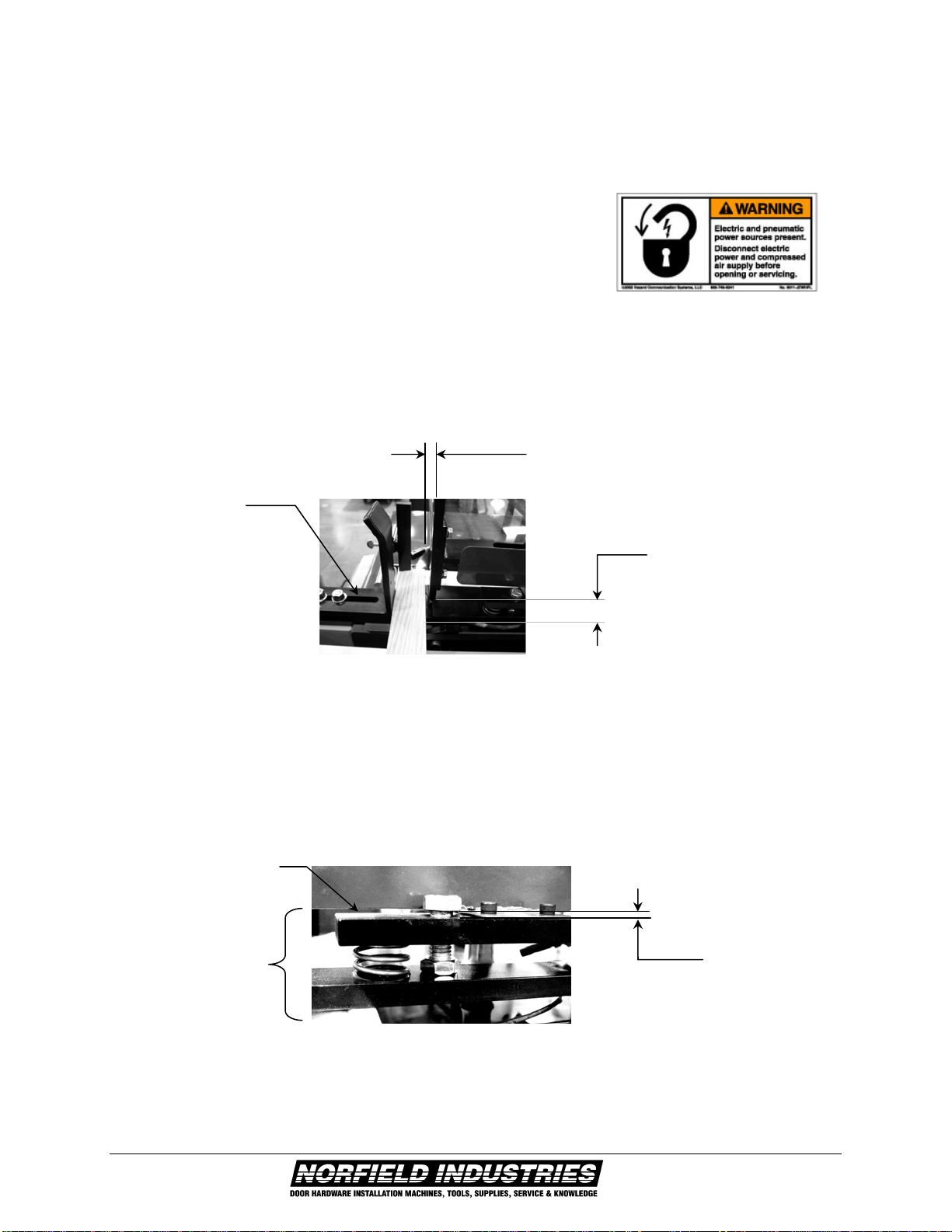
Next, check the Hold-down Ski heights. Manually push the material with the two feed
assemblies into the Hold-down Ski Assembly. Measure the distance from the bottom of the
1/2" hex head bolt to the top of the Ski Adjustment Bar. This distance should be 1/32 to
1/16" max. Refer to Section 2 if any adjustment is required.
I
NSTALLATION
Hold-Down
Ski Assembly 1/32" to
1/16" gap
Ski Adjustment Bar
Feed Magazine
Material Gate
Height 1/16" to 1/8"
gap
Material Gate clearance
1/16" to 3/32" gap
15
When re-energizing
the machine after the
E-Stop has been
depressed the
assemblies will move
back to their home
positions if the saw
cycle was interrupted
in mid cycle.
1.9 BASIC INSTALLATION ADJUSTMENTS (CONT.)
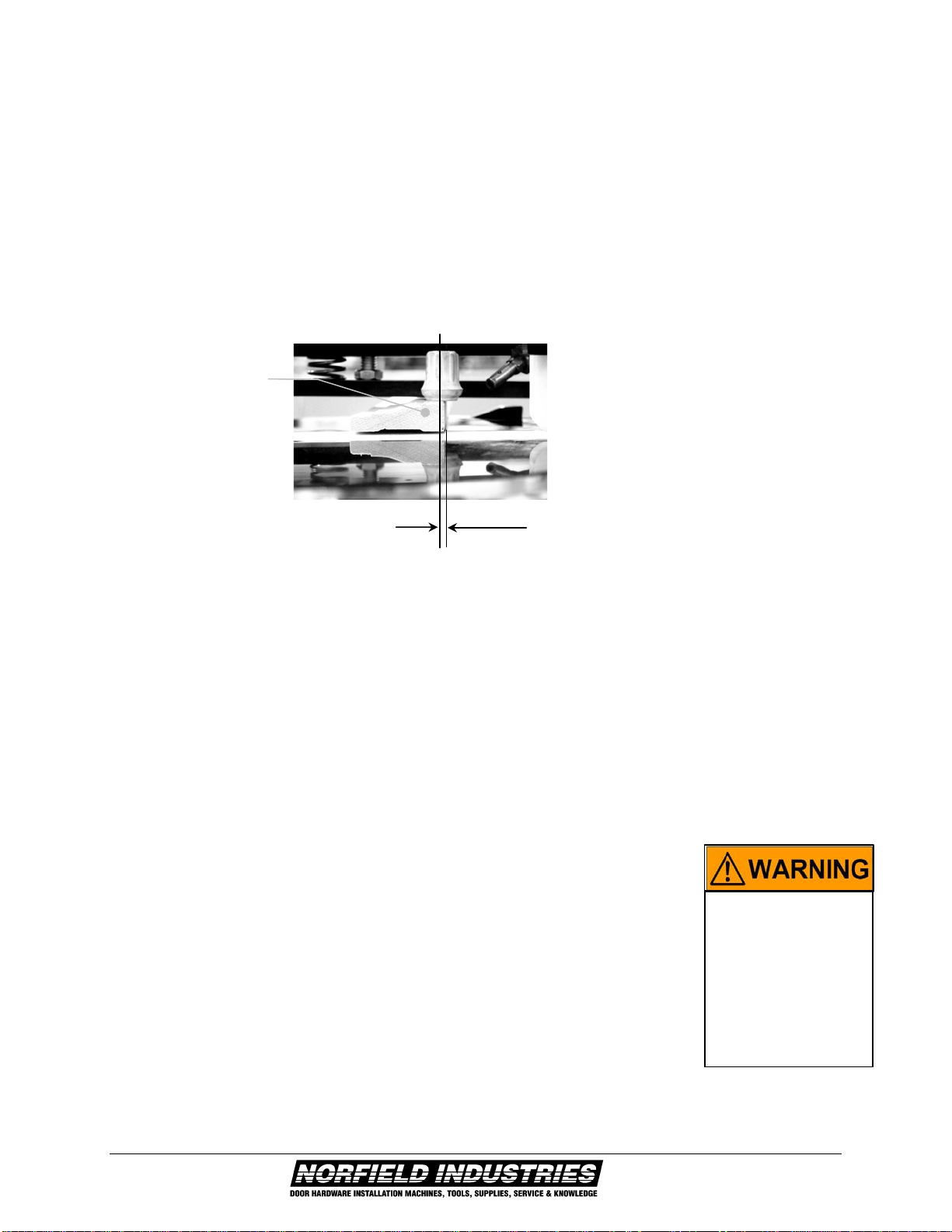
Next, check the position of the Crutch Tip. To do this, manually raise both Crutch Tips until
they stop. Using the two Feed Assemblies manually push the material forward until the feed
assembly comes into contact with the stop. Lower the crutch tips so that they contact the
material. The center of the Crutch Tip should contact the thickest part of the profile of the
material 1/16" to 1/8" in from the leading edge. Refer to Section 2 if any adjustment is
required.
After noting and checking all the above items and making any necessary changes, turn the
main air on, start the saws, start the kerfing unit (if applicable), and then lift the Cycle Start
Lever to begin operation. Let the machine cycle at least 6 times before loading the
magazine. Place material into the magazine only during the return stroke of the feed
mechanism, or after the feed dog has gone forward away from the magazine. If you wish at
any time to stop the machine operation, push the Cycle Start Lever back down to the off
position.
Using the Cycle Start Lever is the recommended way to stop normal
operation of the machine. This is not an Emergency Stop, as the saw will
complete the remainder of its present cycle.
The Emergency Stop switch is located on the Electrical Enclosure, and
when depressed will halt all operations. Both the air and electrical
systems will be interrupted until the switch is reset.
I
NSTALLATION
1/16 to 1/8
Thick part of
material profile

16
1.10 MAJOR COMPONENTS AND CONTROLS
I
NSTALLATION

17
SECTION 2
OPERATIONAL SETTINGS
2.1 QUICK-START GUIDE
The Norfield Industries 1020 DOUBLE END TRIM SAW consists of two saw canisters
supported on a common frame. The left or stationary saw canister is fixed and the right saw
canister is adjustable to allow setting for the desired length of cut. The following
instructions are intended to familiarize the operator with the normal operating settings.
Individual adjustments are covered in greater detail following this section.
1. Before removing any of the Lock-out Tag-out devices on either the main electrical panel
or air supply do the following 3 items:
I. Depress the Emergency Stop Button on the 1020's Electrical Enclosure.
II. Make sure that the Cycle Start Lever and Main Air Lever are in the off
position.
2. Remove the lock-out/tag-out devices.
3. Turn on the air valve located at the Filter/Regulator/Lubricator to supply air to the
machine.
4. Turn the Disconnect Switch to the on position
5. Release the two Head Lock Levers on the right Saw Canister, using the scale provided
set the right saw canister to cut the material to the desired length.
6. Retighten the Head Lock Levers.
7. Next, determine the miter cut needed. For headstock both saws are adjusted to 45
degrees. To cut side trim, one saw will be 45 degrees and the other 90 degrees. The
appropriate hand is achieved using the adjustments knobs located on the front of the
corresponding saw canister.
8. Turn the Turntable Lock Switch to the off position.
9. Select the desired cut, 45 or 90 degrees
10. After the saw has rotated to the set location, change Turntable Lock Switch to the ON
position.
O
PERATIONAL
S
ETTINGS

18
2.1 QUICK-START GUIDE (CONT.)
11. Turn the Main Air Lever to the ON position by moving the lever to the left. Stay clear of
the saw and feed assemblies as they may move unexpectedly when air is applied.
12. Set the Material Stop on the left side for the appropriate position based on that saws
rotational position.
13. If kerfing is desired, and your machine is equipped with this option, the appropriate
selector switch should be turned to the ON position on the Electrical Enclosure. Once
the Saw Motor Start Button is depressed the kerfing motors will start automatically.
14. Rest the Emergency Stop Switch by pulling it out.
15. Start the saw motors by depressing the Saw Motor Start Button on the Electrical
Enclosure.
16. Lift upwards on the Cycle Start Lever, this will activate the saws and the Feed
Assemblies will begin cycling.
17. Load one piece of material into the Magazine. Place material into the Magazine only
when the feed mechanism is returning to pick up material, or after the Feed Dog has
gone forward away from the magazine.
18. Once the material is cut and has passed through the machine return the Cycle Start Lever
to the off position.
19. Turn off the saw motors by depressing the Stop Button located on the electrical
enclosure.
20. Measure the length of material and check the miter for accuracy. If the material does not
meet your specification please proceed to the adjustment section of the manual.
21. Once these checks have been made and you are satisfied with the specifications you are
ready to begin using your new Norfield 1020 double end trim saw.
O
PERATIONAL
S
ETTINGS

19
2.2 SETTING THE MACHINE TO DO MITTER CUTS OR END CUTS
To adjust the saws to perform a 45-degree miter cut or a 90-degree end cut:
1. Unlock the turntable by turning the Turntable Lock Switch to the off position.
2. Switch the Turntable Indicator Knob to either 45 or 90 degrees. The turntable will
automatically rotate the selected angle as soon as the turntable has stopped so that the
spiral pin is in contact with the corresponding adjusting screw.
3. Change the Turntable Lock Switch back to the on position.
4. This completes the change over.
2.3 SETTING UP TO CUT DIFFERENT LENGTHS OF MATERIAL
To set the machine at any given length from 1'6" to 8' you must:
1. Loosen the two Headlock-levers.
2. Turn the adjustment crank clockwise for longer lengths of material, or counterclockwise
for shorter lengths of material.
3. Retighten the two Headlock-levers.
O
PERATIONAL
S
ETTINGS
Head Lock Levers
Length Adjustment crank
Stationary Canister Moveable Canister
Turntable Indicator Knob
Turntable Lock
Kerfing option not
shown

20
Loosen four 1/2"
b
olts
2.4 SETTING UP TO CUT DIFFERENT WIDTH MATERIALS
If the thickness of the material does not change there are only two adjustments to make
when setting the machine for different widths of materials, Please refer to the following:
1. Turn the Disconnect to the off position.
2. Loosen the four 1/2 inch bolts that hold down the Feed Magazine Weldment
3. Insert a piece of material into the magazine.
4. Holding the material against the back of the magazine.
5. Adjust the Feed Magazine Weldment such that the magazine opening has 1/16" to 3/32"
clearance between the material and the Material Gate as shown.
6. Tighten bolts and recheck the clearance at both ends of the machine.
O
PERATIONAL
S
ETTINGS
Material Gate
Feed Magazine
Weldment
1/16" to 1/32"
This manual suits for next models
1
Table of contents


