Norgren Herion XSz User manual
Damping modules
2/2 directional control valve, normally open or closed
for soft clutch engagement
●Compact design
●Simple installation
●Reduction wear and tear
●Noise reduction
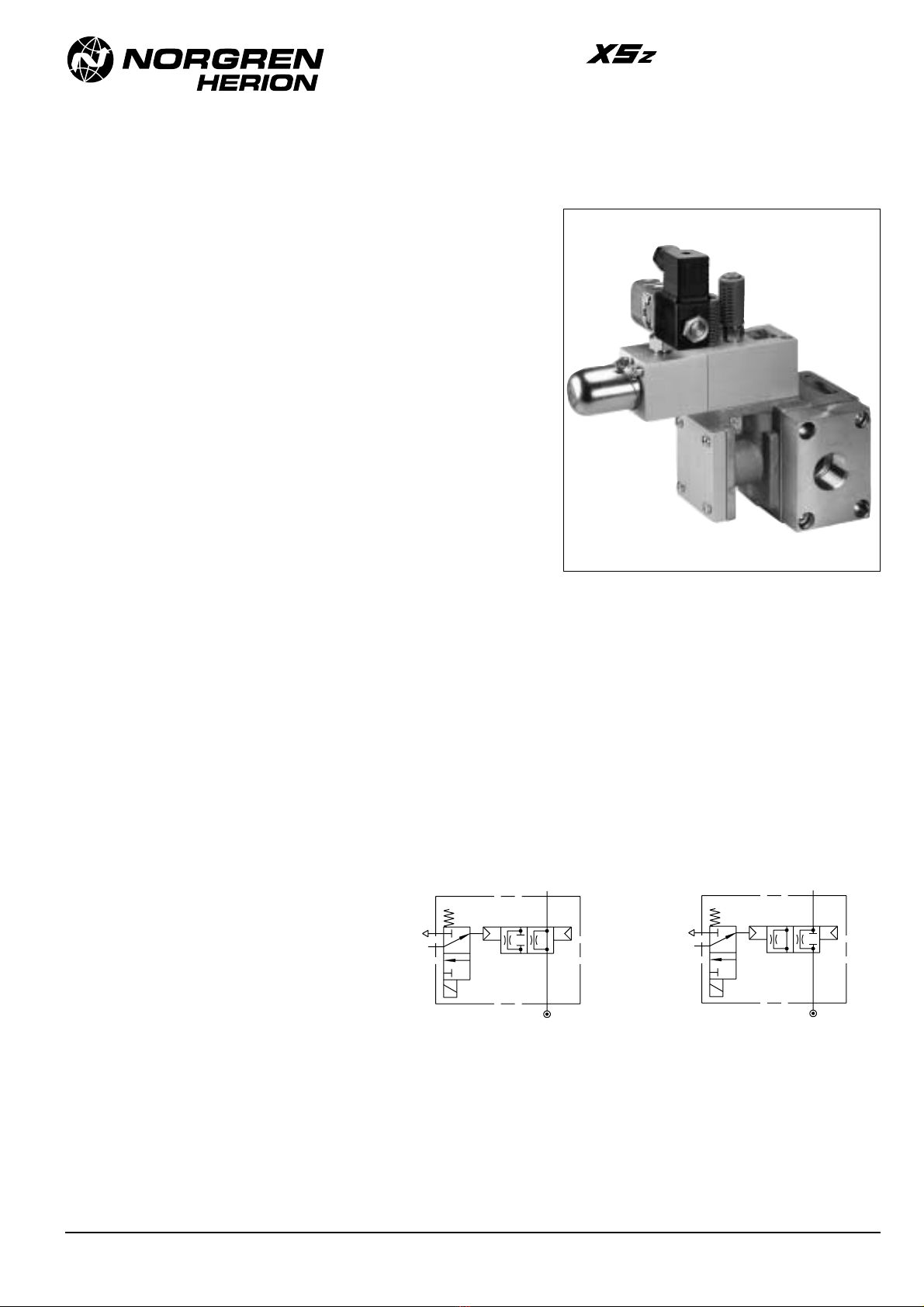
Soft start valve can be used for soft engagement of a
pneumatically operated clutch on presses. It can be directly
flanged on port 1 (P) of the safety valve XS/XSz 32 and
with an adapter plate on the XS/XSz 50. It has a
interchangeable bypass orifice to adapt to individual
operating conditions.
Technical data
Operating pressure:
2 to 8 bar
Fluid:
Filtered and lubricated air 1)
Fluid temperature:
- 10 to + 40 °C 2)
Ambient temperature:
- 10 to + 60 °C 2)
Materials: Housing: Aluminium alloy
Seals: NBR (Perbunan)
AU (Vulkolan)
3 (R)
1 (P)
12 (Z)
2 (A)
1 (P)
3 (R)
1 (P)
12 (Z)
2 (A)
1 (P)
Symbol for Cat. No. 1020113 Symbol for Cat. No. 1020141
Soft start („soft clutch“) valve
1) Oil recommendation: Shell Hydrol DO 32, ESSO Febis K 32 (as of July 1992) or comparable oils with DVI
values < 8 (DIN 53521) and ISO viscosity class 32-46 (DIN 51519).
2) To secure the safety function of the valve at subzero temperatures, it is important that the air is dry
enough to prevent an icing of the valve.
Ordering example:
To order, quote part number, e.g.
1020113.0700 for nominal size 32 soft start
valve for XS/XSz 32 valve, soft starting from 2
bar up.
Caution:
For mounting soft start valve on a
XS/XSz 50 valve an adapter flange plate
(Cat.-No. 0557164) is necessary. It has to be
ordered in addition to the soft start valve.
Our policy is one of continued research and development. We therefore reserve the right
to amend, without notice, the specifications given in this document. N/** 5.11.041•0103/01
Damping modules
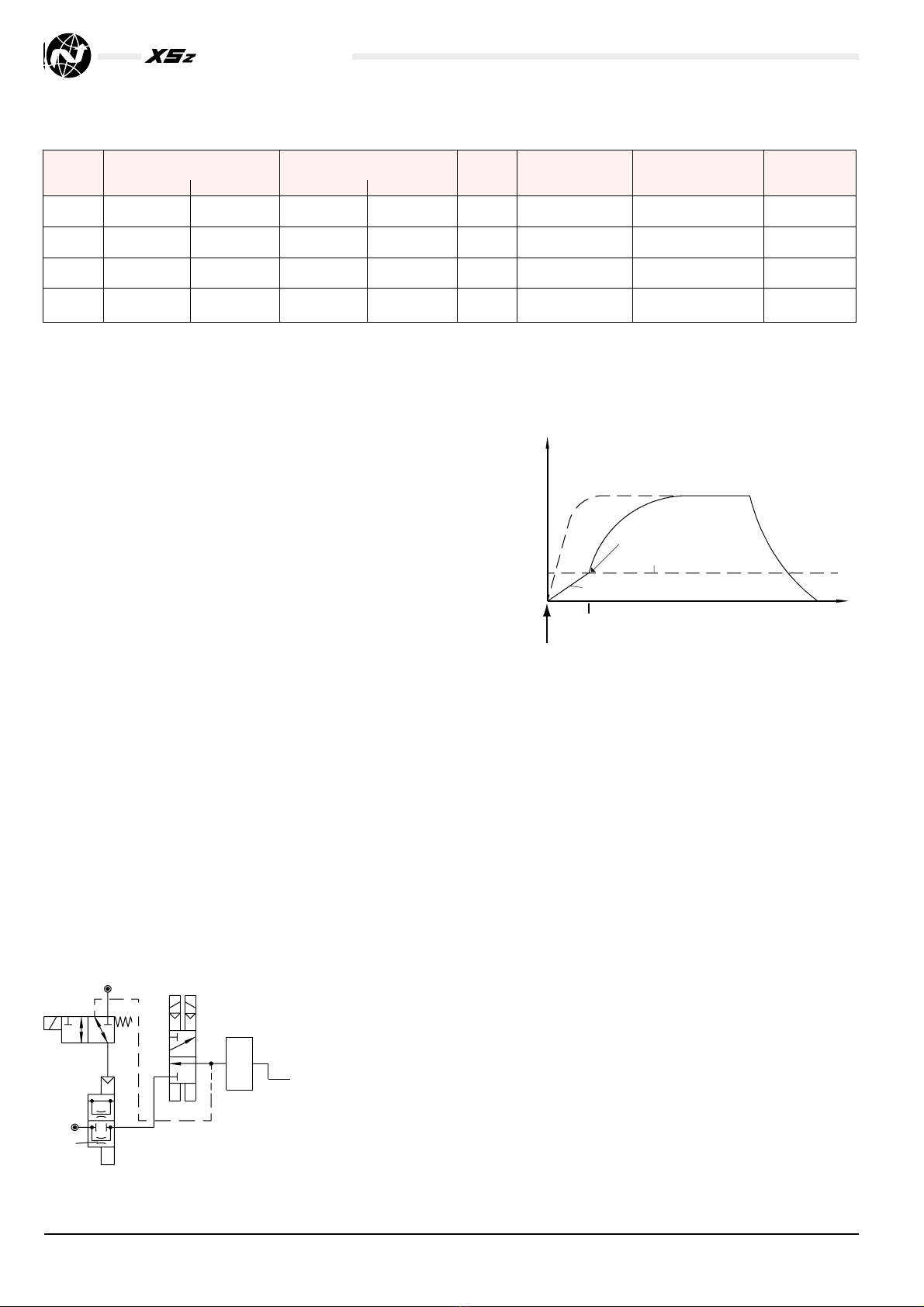
Threshold pressure of clutch from 0 to 2 bar
Switching diagram and characteristic curve
for pressure build-up
M1
2
D
XS / XSz
24
1
C
1
Z
2 (A)
1 (P)
3 (R)
1 (P)
M1energized
Sequence valve (2) closed (Orifice D
2
)
Sequence valve open
t
Threshold pressure of clutch
Stages ab
Pressure
in the
clutch
pe
1
E = Safety valve solenoids (1) are energized
Fig. 1
As shown in Fig. 1 the clutch (C) is vented via safety
valve (1). Pressure supply via filter, lubricator and the
2/2 control valve (2). However, the clutch is shut off by
the safety valve (1). As soon as the solenoids of the
safety valve (1) are energized, the clutch is pressurized
in following two stages:
a) The closed 2/2 directional control valve causes
slow pressure build-up in the clutch via orifice D2,
to a level where the acceleration phase between
flywheel and drive shaft is reached (clutch closes).
b) Via line 4 the 2/2 directional control valve (2) is
switched to the open position initiating a rapid
pressure build-up.
The clutch (C) exhaust through the safety valve (1) as
soon as safety valve solenoids are de-energized
the 2/2 directional control valve (2) is switched to
closed position.
The 3/2 solenoid valve (M1) allows a setup operation
of the press: after switching the solenoid valve (M1)
and the safety valve (1), pressure will build-up at port
2(A) from the safety valve (1).
This operation will cancel the soft engagement
function of the soft start valve.
Adapter plate for flanged versions, Types XS/XSz50, Cat. No. 0557164
General information
Nominal Operating pressure (bar) Control pressure (bar) Weight Cat. no. Notes Voltage
size
(bar) (min. max. min. max. (kg) Valve Solenoid
3 8 0,6 8 4,1 1020113. 0700 Valve for smooth starting DC
from 2 bar up
3 8 0,6 8 4,1 1020113. 3703 Valve for smooth starting AC
from 0 2 up
3 8 0,6 8 4,5 1020141. 0800 Valve for smooth starting DC
from 0 to 2 bar
3 8 0,6 8 4,5 1020141. 3803 Valve for smooth starting AC
from 0 to 2 bar
All solenoids are delivered without plugs. If you require plugs, please order them separately, Cat-No. 0570275.
Our policy is one of continued research and development. We therefore reserve the right
to amend, without notice, the specifications given in this document.
N/** 5.11.041•02 03/01
Advantages of this control are:
●Soft application of the clutch disc, thus reducing the
noise
●Controlled torque transmission reducing clutch wear
and tear
●Due to pressure control, no change in
the performance characteristic caused by clutch wear
and tear
●No need to harmonize clutch volume and volume of
pipe lines between clutch and valve
●No pipe work due to flanged design
●Easy to handle
●Due to pressure adjustment, suited for all clutch
types
●No changes by fluctuations of operating pressure
●The solenoid valve M1 allows a setup operation of the
press.
Threshold pressure of clutch from 0 to 2 bar
Damping modules
M1
2
D
1 (P)
3 (R)
XS / XSz
2 (A)
12 (Z)
24
1
C
1 (P)
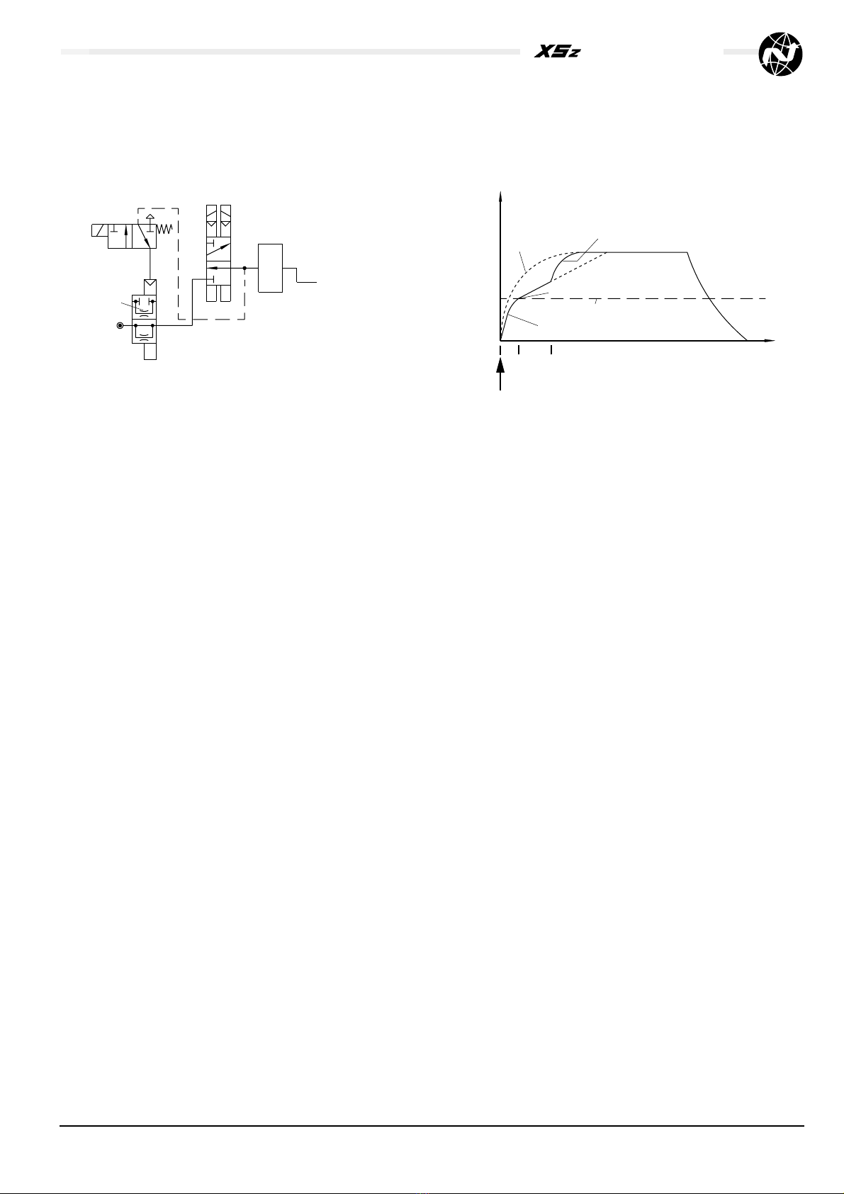
Threshold pressure of clutch from 2 bar up
Switching diagram and characteristic curve for pressure build-up
1
Menergized
Sequence valve closed (orifice D
2
)
Sequence valve open
t
Threshold pressure of clutch
Stages abc
Pressure
in the
clutch
pe
1
I
Menergized
E = Safety valve solenoids (1) are energized
Fig. 2
As shown in Fig. 2 the clutch (C) is vented via safety
valve (1). Pressure supply via filter, lubricator and the
2/2 directional control valve (2). However, the clutch is
shut off by press safety valve (1).
As soon as the solenoids of the safety valve (1) are
energized, the clutch is pressurized in three stages:
a) Fully open, the 2/2 directional control valve (2)
causes a quick pressure build-up to a level where
engagement pressure of the clutch is reached. From
this pressure level, the 2/2 directional control valve (2)
is closed through line 4.
b) Further pressure build-up via orifice D2can be
controlled as the orifice diameter determines the
acceleration period between flywheel and driving shaft.
c) After acceleration phase, M1 is energized, and the
2/2 directional control valve (2) opens. Pressure in the
clutch quickly raises to a pre-set value. Torque
transmission from the flywheel to the crank shaft of the
press is assured.
By de-energizing the solenoid of the safety valve (1),
the clutch is vented; the 2/2 directional control valve (2)
remains in open position.
The 3/2 solenoid valve (M1) allows a setup operation of the
press: after switching the solenoid valve (M1) and the
safety valve (1), pressure will build-up in the clutch. This
operation will cancel the soft engagement function of the
soft start valve.
Our policy is one of continued research and development. We therefore reserve the right
to amend, without notice, the specifications given in this document. N/** 5.11.041•0303/01

Damping modules
G 1/4
G 1/4 Solenoid valve Type 9602340.0700 (DC) / 9602340.3703 (AC)
Silencer at Z1 and 3 (R)
(included in type 1020113.0700)
Solenoid valve Type 2401103.0800(DC) / 2401103.3803 (AC)
Silencer at Z and 3 (R)
(enclosed in type 1020141.0800)
approx. 260
165
12 (Z) 3 (R)
G 1/8
52
80
1 (P)
40
78
235
12 (Z) 3 (R)
q 50
2
G 1
M8
1 (P)
105
M10
Adapter plate
type 0557164
for XS / XSZ 50
13 25
96
159
(Z1)
1
12
changeable bypass
orifice D2
(Z1)
1
12
A suitable air treatment unit (dehydration, filtration, lubrication) must be connected upstream of pressure port P. Lubrication can be omitted if the connected consuming device and all additional
equipment is suited for oil-free operation (see page 1). Degree of filtration: 5 µm.
It is the responsibility of the purchaser and/or installer of the Norgren-Herion safety valves to make sure that the valve and all other components comply with all relevant national regulations and the
specifications of the local safety associations.
The valve should be checked at intervals depending on the loads to which it is subjected, at least, however, once a year. The relevant tests must be carried out according to the corresponding operation
and maintenance instructions of the unit and the local safety regulations. In case of malfunctions the unit has to be tested and/or replaced immediately.
For information on installation, operation and maintenance of the damping modules please see maintenance manual no. 5.4.3 6.
All liability is denied for unauthorised modification of the units, installation or usage not in accordance with the manual, the local safety re uirements or the principles
of EN 692 and EN 954-1.
Our policy is one of continued research and development. We therefore reserve the right
to amend, without notice, the specifications given in this document.
N/** 5.11.041•04 03/01
Table of contents
Popular Control Unit manuals by other brands

Grundfos
Grundfos LC 108 Installation and operating instructions

Viessmann
Viessmann EM-P1 Installation and service instructions

Val-Matic
Val-Matic 100S Operation, maintenance and installation manual

EFI
EFI EB-32 Installation and service guide

Emerson
Emerson Fisher N551 instruction manual

Siemens
Siemens SIMATIC ET 200SP TM ECC 2xPWM ST product manual

Weinzierl
Weinzierl KNX RF/TP Coupler 673 secure Operation and installation manual

Tyco
Tyco DV-5A manual

Johnson Controls
Johnson Controls M300CJ-R Installation and maintenance instructions

Dwyer Instruments
Dwyer Instruments DP3 Series Installation and operating instructions

Definox
Definox VDCI-MC PFA manual

Beijing
Beijing DAM-E3311 user manual


