DELTA DORE DELTA 8000 BT User manual

EN Technical unit for Delta 8000 system
DELTA 8000 BT
Installation instructions

22 23
EN
CONTENTS
1/ Overview of the technical unit 24
2/ Mounting and connecting the
technical unit 25
3/ Connecting the technical unit's
inputs/outputs 27
4/ Application examples 28
4.1 Hard-wired 28
4.2 Wireless (option) 30
4.3 Hybrid hard-wired and wireless 31
4.4 Extension (option) 31
5/ Switch conguration 32
6/ Associating a room thermostat with
a technical unit 33
6.1 With a Room Thermostat (RT) 33
6.2 With a Programmable Room Thermostat (PRT) 34
7/ Conguring the technical unit 35
7.1 With a room thermostat (RT) 35
7.2 With a programmable room thermostat (PRT)
or programmer (PROG) 36
8/ Restoring the technical unit to
factory settings 37
8.1 With a room thermostat (RT) 37
8.2 With a programmable room thermostat (PRT)
or programmer (PROG) 38
9/ Water temperature monitoring 39
10/ Troubleshooting 40
11/ Technical characteristics 41

24 25
EN
❶Remove the cover
❷Mount the unit with a set of screws/sprigs
compatible with the substrate
(not included).
❸Connect the elements
(refer to the 'connection' §).
Fasten the cables using the nylon screws
provided.
❹Remove the temporary partitions to run
the cables to the required locations,
then close the unit.
2/ MOUNTING AND CONNECTING THE
TECHNICAL UNIT
Green Status
LED (ST)
Red circulator and burner
LEDs (P and G)
Red valve
LEDs (1 to 8)
On Normal
operation
Relay closed
Output on On
Off Initial heating
of the slab
Relay open
Output off Off
Slow fl ashing
... ... ...
.. .. .. .. ..
Association mode - -
Quick fl ashing
... ... ...
.. .. .. .. ..
Defect in progress - Defect in
progress
1
ON
6
5
4
32
DIP
88
7
Con guration
switches
Status LED
Water
monitoring input
Circulator LED
Burner LED
Change-over
input/output
Valve outputs
Valve supply
Master switch
Bus
Valve output LEDs
1/ OVERVIEW OF THE TECHNICAL UNIT
1
ON
6
5
4
32
DIP
88
7
DIP
1
ON
6
5
4
32
DIP
88
7
Ê
Ë
Ì
Í
Burner and
circulator outputs

26 27
EN
Switch off the mains power before handling the device.
❶Water monitoring input (option) by CTN sensor or dew point sensor
(according to SW8 conguration)
❷ Change-over input or output (according to SW6 conguration). If change-over output:
voltage off load < 28VDC, current < 50mA. Ensure the wires are correctly connected!
❸To connect the Bus, use the cable supplied (2x0.75², length 1 m) or twisted pair cable with
a minimum section of 6/10th, max. length. 30 m:
- 4 wires maximum per terminal
- Ensure the wires are correctly connected to the + and - poles.
- Room terminals can be connected to either one of the 2 Bus terminals.
❹Burner and circulator outputs, dry contact 2A Max, 230V~
❺Valve outputs. If you use 3 position actuators, you will only be able to connect 4 valves to
the technical unit (switch SW3 = ON).
If you need more outputs, use another technical unit in 'Extension' mode.
❻Valve power supply 24VAC/DC or 230 V~ / 240 V~.
❼Main power supply 230 V~ / 240 V~
Y1 Y2 Y3 Y4 Y5 Y6 Y7 Y8
5 6 7 8 9 10 11 12 13 14 15 16 17 18 19 20
Y1
SW3 = OFF
SW3 = ON
N
NNNNNNNN
N N N N N N NY2 Y3 Y4 Y5 Y6 Y7 Y8
5 6 7 8 9 10 11 12 13 14 15 16 17 18 19 20
2 position actuators
3 position actuators
Z1 to Z8 max.
Z1 to Z4 max.
3/ CONNECTING THE TECHNICAL UNIT'S
INPUTS/OUTPUTS
1
ON
6
5
4
32
DIP
88
7
1 2 3 4 5 6 7
1 2 3 4 5 6 7
I0
Power supply
S
GENERAL
VALVE ACTUATORS
BUS
5 6 7 8 9 10 11 12 13 14 15 16 17 18 19 20 23 241 2 3 4
AUXILIARIES
Y1 Y2 Y3 Y4 Y5 Y6 Y7 Y8 L NN N N N N N N N
Power supply
21 22
LN

28 29
EN
Bus
30m max.
BT Master
SW1 = OFF
BT Extension
SW1 = ON
1 -> 8 sorties
1
ON
6
5
4
32
DIP
88
7
1
ON
6
5
4
32
DIP
88
7
BUS 1 BUS 2
BUS
Bus
30m max.
Bus
30m max.
1-> 8 sorties max.
1-> 8 sorties max.
1-> 8 sorties max.
1-> 8 sorties max.
BUS 1 BUS 2
BUS
Bus
30m max.
BUS 1 BUS 2
BUS
RT
zone 1
RT
zone 2 RT zone N
4/ APPLICATION EXAMPLES
If the system is without
programming, one of the
thermostats must be set to
'Master' mode (refer to the
thermostat manual).
If the system is without
centralized programming,
one of the thermostats must
be set to 'Master' mode (refer
to the thermostat manual).
PRT
zone 1
PRT zone 2 PRT zone N
Bus
30m max.
BT Master
SW1 = OFF
BT Extension
SW1 = ON
1 -> 8 sorties
1
ON
6
5
4
32
DIP
88
7
1
ON
6
5
4
32
DIP
88
7
BUS 1 BUS 2
BUS
Bus
30m max.
Bus
30m max.
1-> 8 sorties max.
1-> 8 sorties max.
1-> 8 sorties max.
1-> 8 sorties max.
BUS 1 BUS 2
BUS
Bus
30m max.
BUS 1 BUS 2
BUS
Example 3: Regulation with room by room programming
PRT: Programmable Room Thermostat
Programmer
RT
zone 1
RT
zone 2 RT
zone N
Bus
30m max.
BT Master
SW1 = OFF
BT Extension
SW1 = ON
1 -> 8 sorties
1
ON
6
5
4
32
DIP
88
7
1
ON
6
5
4
32
DIP
88
7
BUS 1 BUS 2
BUS
Bus
30m max.
Bus
30m max.
1-> 8 sorties max.
1-> 8 sorties max.
1-> 8 sorties max.
1-> 8 sorties max.
BUS 1 BUS 2
BUS
Bus
30m max.
BUS 1 BUS 2
BUS
Example 2: Room by room regulation with centralised programming
4.1 HARD-WIRED
Example 1: Room by room regulation without programming
RT: Room thermostat

30 31
EN
Bus
30m max.
BT Master
SW1 = OFF
BT Extension
SW1 = ON
1 -> 8 sorties
1
ON
6
5
4
32
DIP
88
7
1
ON
6
5
4
32
DIP
88
7
BUS 1 BUS 2
BUS
Bus
30m max.
Bus
30m max.
1-> 8 sorties max.
1-> 8 sorties max.
1-> 8 sorties max.
1-> 8 sorties max.
BUS 1 BUS 2
BUS
Bus
30m max.
BUS 1 BUS 2
BUS
Bus
30m max.
BUS 1 BUS 2
BUS
1-> 8 sorties max.
Wireless
programmer
Radio/bus
gateway
Technical
unit Wireless room
thermostats
Hard-wired
room
thermostats
4/ APPLICATION EXAMPLES
4.2 WIRELESS (OPTION)
Associating the radio/Bus gateway with the technical unit will enable access to the range's
wireless products and functions:
- Wireless room thermostats (room by room regulation),
- Wireless programmers (centralised programming),
- Wireless programmable thermostats (regulation + room by room programming),
- Window magnetic contacts: activates the Frost Protection mode when a window is
opened.
- Presence/absence detectors: lower the temperature setting when the premises are left
empty for a long period of time.
- Outdoor temperature sensor.
Bus
1-> 8 sorties max.
Wireless
programmer
Radio/bus
gateway
Technical unit
Room
thermostats
Wireless
4.3 HYBRID HARD-WIRED AND WIRELESS
Wireless and hard-wired solutions can be used concomitantly on the same installation :
- Room thermostats (room by room regulation),
- Programmers (centralised programming),
- Programmable thermostats (room by room regulation + programming),
Example:
4.4 EXTENSION (OPTION)
Another technical unit is added to control up to 16 outputs.

32 33
EN
SW1 Conguring the
technical unit
OFF Master
ON Extension (refer to the 'Extension option' §)
SW2 Production mode OFF Heat (boiler or non reversible heat pump)
ON Heat/Cool (reversible heat pump)
SW3 Valve actuator type
OFF Thermal 2 positions (number of outputs 8 max.)
ON Motorised 3 positions (number of outputs 4max.)
SW4 Valve control direction OFF Normally closed
ON Normally open
SW5 Override mode
(e.g: initial heating)
OFF No
ON Yes (valves and circulator active)
SW6
Heat pump change-over
communication
direction
OFF Heat pump to Technical Unit (Change-over input). The
heat pump delivers its production mode to the TU.
ON TU to heat pump (change-over output). The TU delivers
its production mode to the heat pump.
SW7 Heat pump change-over
conguration
OFF Contact closed= Heat mode
Contact open = Cool mode
ON Contact closed= Cool mode
Contact open = Heat mode
SW8
Type of 'water
monitoring'
measurement.
OFF
Absence of dew point measurement or sensor with
a Delta Dore condensation sensor (For cooling only,
shuts the system down if condensation is detected).
ON
Initial Cool or Heat temperature with CTN 10KW
sensor at 25°C (shuts the system down if the water is
too hot or too cool).
1
ON
6
5
4
32
DIP
88
7
SW5: Override mode
This mode overrides the 100% operation for initial heating. Set switch 5 to ON.
On the technical unit, the circulator LED and valve output LEDs are illuminat d. The 'Status'
LED is off.
On the room thermostat (RT) or the programmable thermostat (PRT) a
specic display indicates that initial heating is in progress.
All the switches are set to OFF by default.
HP: Heat pump TU: Technical unit
5/ SWITCH CONFIGURATION 6/ ASSOCIATING A ROOM THERMOSTAT WITH
A TECHNICAL UNIT
Example:
Associated outputs (CF20) Controlled outputs
Thermostat 1 1 Y1, Y2, Y3
Thermostat 2 4 Y4, Y5
Thermostat 3 6 Y6, Y7, Y8
Y1 N N N N N N N NY2 Y3 Y4 Y5 Y6 Y7 Y8
5 6 7 8 9 10 11 12 13 14 15 16 17 18 19 20
Th 1 Th 2 Th 3
6.1 WITH A ROOM THERMOSTAT (RT)
❶Press and hold the 1st and 4th button for 3 seconds,
then release.
❷The screen displays CF20. Press OK to open the setting,
then press + and - to select the output with which the
thermostat will be associated.
Conrm with OK.
❸The screen displays CF21.
Select the transmitter and press OK.
❹The screen displays CF05.
Select the thermostat type and press OK.
3 s
1
2
(1) Output number 1 to 16 depending on the system.
Transmitter type
0Underoor heating
1 Heater
2 Ceiling or ductable
(2) Thermostat type 0 Zone thermostat
1 Master Thermostat
(2) CF05: the Master thermostat enables the centralised use of ON/OFF and HEAT/COOL
(at least one Master thermostat is required in an installation without a programmer).

34 35
EN
6/ ASSOCIATING A ROOM THERMOSTAT WITH
A TECHNICAL UNIT
(1) Output number 1 to 16 depending on the system.
Transmitter type 0Underoor heating
1 Heater
Heating percentage
limitation
From 10 to 100% in 10 increments (100%= No
limitation, by default).
6.2 WITH A PROGRAMMABLE ROOM
THERMOSTAT (PRT)
❶Turn the selector knob to .
❷Press and hold the 2nd button from the left for 3 seconds.
Release.
❸The screen displays Ln01. Press OK to open the
association mode.
❹The screen displays CF20. Press OK to open the setting,
then press + and - to select the output with which the
thermostat is to be associated.
Conrm with OK.
❺The screen displays CF21. Select the transmitter and
press OK.
❻The screen displays CF22.
Select the limitation value and press OK to conrm.
To exit the current mode, press or turn the dial.
3 s
(1) CF20: a product associated with an output also controls the following outputs in the same
manner, if these are not associated.
7/ CONFIGURING THE TECHNICAL UNIT
5 s
3 s
7.1 WITH A ROOM THERMOSTAT (RT)
❶From the OFF mode, press and hold the 2nd button
from the left for 5 seconds.
Release.
❷Press and hold OK for 3 seconds. Release.
❸The screen displays CL01.
• Press + or - to select the parameter to be set
(CL01 to CL08).
• Press OK to open the setting mode, then + and - to
perform the setting.
❹ Conrm with OK.

36 37
EN
Valve opening time 1 to 10 minutes in 30s increments (3 mn by default)
Not used
Frost Protection
(in system OFF mode)
0 Frost Protection mode authorised
1 No Frost Protection security
(1) Passive cooling 0 Not authorised
1 Allowed
(2) Max. ow water
temperature limit 45°C to 75°C in 5°C increments (50°C by default)
(2) Min. ow water
temperature limit 5°C to 30°C in 1°C increments (22°C by default)
Not used
7.2 WITH A PROGRAMMABLE ROOM THERMOSTAT (PRT)
OR PROGRAMMER (PROG)
❶Turn the selector knob to .
❷Press and hold OK for 3 seconds.
❸The screen displays CL01.
• Press + or - to select the parameter to be set (CL01 to CL08).
• Press OK to open the setting mode, then + and - to perform
the setting.
❹ Conrm with OK.
(1) CL04 only appears in Heat production mode (SW2=OFF), refer to the technical unit's
manual and for underoor heating (CF21 =0) or for ceiling/ductable (CF21 = 2).
Passive cooling: water ow for cooling (heating in OFF mode).
(2) CL06/CL07: if the limit is exceeded or reaches -> switch over to OFF mode. The defect
comes up on the thermostat screen (see 'Troubleshooting - Water monitoring input' §).
7/ CONFIGURING THE TECHNICAL UNIT
3 s
8/ RESTORING THE TECHNICAL UNIT TO
FACTORY SETTINGS
20 s
3 s
8.1 WITH A ROOM THERMOSTAT (RT)
❶From the OFF mode, Simultaneously press and hold the
1st and 3rd buttons from the left (i) for 20 seconds.
❷After 10 seconds, the screen displays rSt1.
Keep the button pressed until the screen displays rSt2.
Release.
❸Press and hold OK for 3 seconds until the rSt2
display ashes.
The system automatically returns to Shutdown
(or OFF mode).

38 39
EN
8.2 WITH A PROGRAMMABLE ROOM THERMOSTAT (PRT)
OR PROGRAMMER (PROG)
❶From the OFF mode, Simultaneously press and hold the
1st and 4th buttons from the left (i) for 20 seconds.
❷After 10 seconds, the screen displays rSt1.
Keep the button pressed until the screen displays rSt2.
Release.
❸Press and hold OK for 3 seconds until the rSt2 display
ashes.
The system automatically returns to Shutdown
(or OFF mode).
8/ RESTORING THE TECHNICAL UNIT TO
FACTORY SETTINGS
20 s
3 s
The multizone kit offers an optional water network temperature monitoring function
(hot and cold).
This function protects the system from overheating in the water network (protection of
the slab and pipes) or from abnormally low temperature, which will generally lead to the
formation of condensation on the ooring.
This information is immediately sent to the end user via a defect fed back to
the room thermostat.
Important: this feature still requires the connection of a safety device to the system
(bimetallic strip on the circulator or condensation sensor) aimed to monitor the system's
water temperature and to cut off the water ow if necessary.
Principle for the detection of excessively hot or cold water
Depending on the entered temperature limit value (to be set at the time of installation),
the system scans the water temperature and reconciles it with the set limit value. If the
water temperature is above (if the water is too hot) or below (if the water is too cold) the
limit value after 30 minutes of circulator operation, the defect is detected and sent to the
thermostat.
If a defect is found, the circulator is shut down immediately.
The system switches the thermostat to OFF mode.
The user must then contact the installer for a diagnosis or work on the heat pump or boiler
in order to reduce the hot water ow temperature setting or feed the cold water setting
back to the system.
The system can be restarted manually from a Master thermostat or a programmer.
The water network's temperature monitoring function is reactivated.
9/ WATER TEMPERATURE MONITORING
40 41
EN
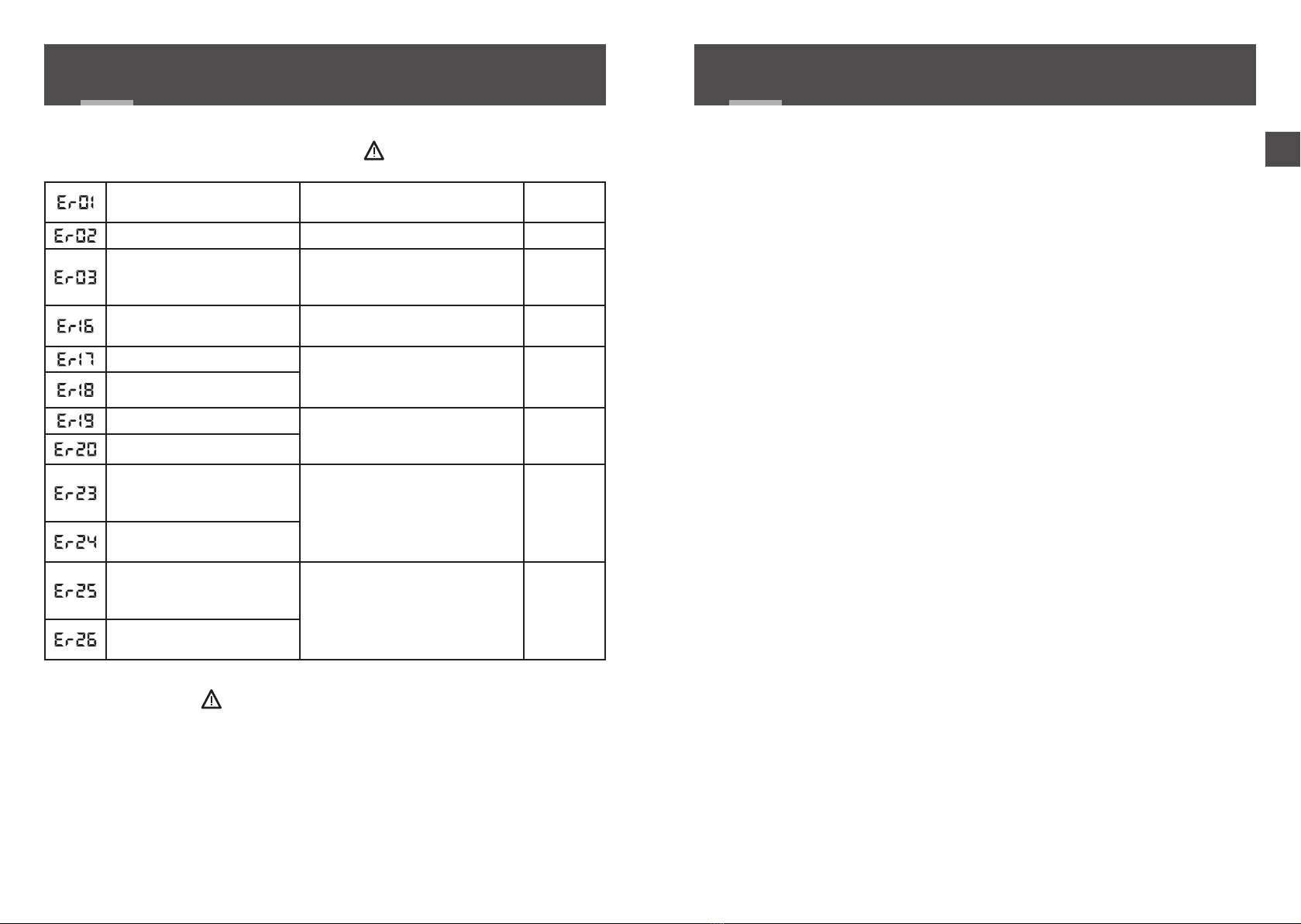
When a defect is detected on the system, the symbol ashes on the room unit display.
Press 'i' to display the type of defect.
Error messages
After viewing, the symbol is displayed continuously until the problem is xed.
Downgraded mode
The technical unit operates in downgraded mode (30% in Heat, OFF and Cool mode),
for each channel, when:
- thermostat signal missing for over one hour (the red LED for the way blinks quickly),
- temperature sensor shorted.
- temperature sensor off.
Bus defect Check connection between the
room unit and the technical unit.
Green LED
ashing
RF defect -
Master TU missing defect
The technical unit must be cong-
ured as 'Master TU'.
Switch SW1 to OFF.
Green LED
ashing
TU address defect Green LED
ashing
Flow sensor shorted.
Check the sensor's connections. Green LED
ashing
Flow sensor cut off or missing
Feed water too hot Set the initial temperatures in the
technical unit conguration menu
('CL06, 07 or 08' menu).
Green LED
ashing
Inowing water too cool
Radio reception defect on
an associated door/window
magnetic contact
Check the radio association.
Check if the installation is not
affected by disturbances.
Move your products around to
check the radio range.
-
Radio reception defect on an
associated presence detector
Battery of an associated
window magnetic contact
defective Replace the batteries of the prod-
uct in question -
Battery of an associated
presence detector defective
10/ TROUBLESHOOTING
• Main power supply 230V~/240V~, +/-10%, 50/60 Hz,
• Valve power supply (24V~/= or 230V~/240V~): 4A Max for all valves
• Consumption: 2 to 15 VA depending on the number of elements connected to the bus and
the number and type of controlled valve actuator
• 8 outputs powered working contact for controlling the valves
Permanent current: 1A Max per output, 230V~/240V~ +/-10%
Accepted inrush current: 2A max. per channel, 6A max. for all channels
• 2 dry contact outputs controlling the burner and circulator (2A Max per output,
230V~/240V~ +/-10%)
• 1 change-over input or output (according to SW6 conguration).
• 2 communication buses for connecting the thermostats (star cabling)
• 1.C action (brownout)
• Class II insulation
• Surface-mounted
• Dimensions: 250 x 95 x 43 mm
• Degree of protection: IP 33
• Operating temperature: 0°C to +50°C
• Storage temperature: -10°C to +70°C
• Installation in an environment with normal pollution levels
• Anti-seize function (automatic start-up 1 to 10 minutes/week if the event that the valve
and circulator remain idle)
11/ TECHNICAL CHARACTERISTICS

www.deltadore.com
09/18
Table of contents
Other DELTA DORE Control Unit manuals

DELTA DORE
DELTA DORE Pack TYXIA 500 User manual

DELTA DORE
DELTA DORE TYXIA 4940 User manual

DELTA DORE
DELTA DORE PACK DELTA 8000 BUS CO 1.1 User manual

DELTA DORE
DELTA DORE DVR TYXAL+ User manual

DELTA DORE
DELTA DORE TYXIA 4940 User manual

DELTA DORE
DELTA DORE TYXIA 4910 User manual

DELTA DORE
DELTA DORE 6351034 User manual

DELTA DORE
DELTA DORE TYXIA 4600 User manual

DELTA DORE
DELTA DORE TYXIA 4910 User manual

DELTA DORE
DELTA DORE TYXIA 253 User manual


