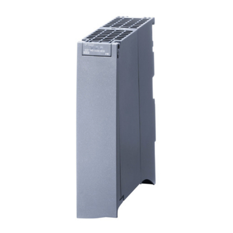
North Atlantic NIU1A User manual

Artisan Technology Group is your source for quality
new and certied-used/pre-owned equipment
• FAST SHIPPING AND
DELIVERY
• TENS OF THOUSANDS OF
IN-STOCK ITEMS
• EQUIPMENT DEMOS
• HUNDREDS OF
MANUFACTURERS
SUPPORTED
• LEASING/MONTHLY
RENTALS
• ITAR CERTIFIED
SECURE ASSET SOLUTIONS
SERVICE CENTER REPAIRS
Experienced engineers and technicians on staff
at our full-service, in-house repair center
WE BUY USED EQUIPMENT
Sell your excess, underutilized, and idle used equipment
We also offer credit for buy-backs and trade-ins
www.artisantg.com/WeBuyEquipment
REMOTE INSPECTION
Remotely inspect equipment before purchasing with
our interactive website at www.instraview.com
LOOKING FOR MORE INFORMATION?
Visit us on the web at www.artisantg.com for more
information on price quotations, drivers, technical
specications, manuals, and documentation
Contact us: (888) 88-SOURCE | sales@artisantg.com | www.artisantg.com
SM
View
Instra

Hardware Manual – NIU1A
North Atlantic Industries, Inc.
8/15/2018
Rev: A7
www.naii.com
Page 1 of 62
NIU1A
Nano Interface Unit
HARDWARE MANUAL

Revision History
Hardware Manual – NIU1A
North Atlantic Industries, Inc.
8/15/2018
Rev: A7
www.naii.com
Page 2 of 62
Revision History
Revision
Revision Date
Description
Author
A
2/1/2018
ECO C05359, initial release of motherboard
manuals.
SL
A1
2/13/2018
ECO C05364, corrections to I/O pinouts.
SL
A2
2/21/2018
ECO C05374, corrections to technical data in
manuals
SL
A3
3/2/2018
ECO C05396, update to block diagram
SL
A4
3/14/2018
ECO C05447, update to OID drawing,
environmental specs
SL
A5
3/28/2018
ECO C05470, update to ethernet section to include
instructions on how to disable the ethernet listener
SL
A6
5/21/2018
ECO C05614, update to available function modules
section and environmental specification.
SL
A7
8/15/2018
ECO C05798, update to available function modules
section
SL

NIU1A
Nano Interface Unit
Hardware Manual – NIU1A
North Atlantic Industries, Inc.
8/15/2018
Rev: A7
www.naii.com
Page 3 of 62
NIU1A – Nano Interface Unit
I/O Interface with optional ARM1 Processor
Configured to Customize
The NIU1A is a small, rugged, low-power, system. It consists of an integrated power supply, one function slot which can be
configured with a field-proven, NAI Intelligent I/O and Communications function module, and an optional ARM®Cortex®-A9
processor. Ideally suited for rugged Mil-Aero applications, the NIU1A delivers off-the-shelf solutions that accelerate
deployment of SWaP-optimized systems in air, land and sea applications.
Features
Made in the USA
4 GB SATA II NAND Flash
(up to 32 GB option)
<15 W motherboard (MB)
power dissipation
1x RS232 Debug port with
ARM option
Wind River®VxWorks®and
Xilinx® PetaLinux OS
Support
Continuous Background
Built-in-Test
COSA®Architecture
US Army VICTORY
Interface Services (Contact
factory)
Commercial and rugged
applications
Operating temp: -40° C to
71° C conduction cooled
28 VDC input
Supports 1 Intelligent I/O function
module
2x 10/100/1000 Base-T Ethernet or
1x 10/100/1000 Base-T Ethernet
and USB
MIL-STD-461F*, MIL-STD-704A
1.7" x 6.8" x 2.5" (incl. connectors)
approx. 1.2 lbs. (545 g) with 3
mounting options
128 MB DDR3 SDRAM
Optional ARM® Cortex®-A9
Dual-Core 800MHz Processor

NIU1A
Nano Interface Unit
Hardware Manual – NIU1A
North Atlantic Industries, Inc.
8/15/2018
Rev: A7
www.naii.com
Page 4 of 62
Select one independent function for your application
I/O
Measurement & Simulation
A/D
±1.25 VDC to±100 VDC or0-25 mA; 16 or 24-Bit;12 or 16 Ch
Synchro/Resolver-Digital
16-Bit; ±1Arc-Min accuracy; 4 Ch
D/A
±1.25 VDC to±80 VDC or ±25 mA to 100 mA;16-Bit, 4-16 Ch
LVDT/RVDT-Digital
16-Bit resolution; 4 Ch
Discrete
0 to 60 VDC; Sink, source or push/pull; up to 24 Ch
Digital-Synchro/Resolver
16-Bit; Up to 3 VA; 1-3 Ch
Isolated Discrete
0 to ±80 VAC or VDC; 16 Ch
Digital-LVDT/RVDT
16-Bit; Up to 3 VA; 1-3 Ch
Relay
SPDT; 4 Ch
AC Reference
2 to 115 VRMS; Up to 6 VA; 1 Ch
TTL
0 to 5.5 VDC; 24 Ch
RTD
16-Bit; 2, 3 or 4-wire; 8 Ch
Differential
Transceiver
Up to ±12V; 422/485 Pulse Gen/Meas;16 Ch Thermocouple J, K, T, E, R, S, B, N; 4 Ch
Communications
Strain Gage
16-Bit; 4 Ch
MIL-STD-1553
Quad Ch Dual Redundant; Transformer or Direct
RS-232/422/423/485
4 Ch
ARINC 429/575
12 Ch
CANBus
8 Ch
Architected for Versatility
NAI’s Custom-On-Standard Architecture™ (COSA®) offers a choice of over 40 intelligent I/O and communications options.
Preexisting, fully-tested functions can be selected to quickly and easily meet system requirements. Individually dedicated I/O
and communications processors allow mission computers to manage, monitor and control via single or dual Ethernet.
All products are designed to operate under extreme temperature, shock, vibration and EMI environments. EMI filters and
gaskets meet or exceed MIL-STD-461F* and MIL-STD-810G requirements.
Board Support Package (BSP) and Software Development Kit (SDK) Support
The NIU1A includes BSP and SDK support for Wind River® VxWorks® and Xilinx® PetaLinux OS Support. In addition,
software support kits are supplied, with source code and board-specific library I/O APIs, to facilitate system integration. Each
I/O function has dedicated processing, unburdening the SBC from unnecessary data management overhead.
Background Built-In-Test (BIT)
BIT continuously monitors the status of all I/O during normal operations and is totally transparent to the user. SBC resources
are not consumed while executing BIT routines. This simplifies maintenance, assures operational readiness, reduces life-cycle
costs and - keeps your systems mission ready.
One-Source Efficiencies
Eliminate man-months of integration with a configured, field-proven system from NAI. Specification to deployment is a
seamless experience as all design, state-of-the-art manufacturing, assembly and test are performed— by one trusted source.
Product Lifecycle Management
From design-in to production, and beyond, NAI’s product lifecycle management strategy ensures the long-term availability of
COTS products through configuration management, technology refresh, and obsolescence component purchase and storage.
*MIL-STD-461F requires properly shielded cables and system practices.
Specifications are subject to change without notice. All productand company names are trademarks orregistered trademarks of their respective holders.

NIU1A
Nano Interface Unit
Hardware Manual – NIU1A
North Atlantic Industries, Inc.
8/15/2018
Rev: A7
www.naii.com
Page 5 of 62
Available Function Modules
GEN5 (SERDES/SBC) Platforms
Specification summaries are provided here. For detailed
specifications, see Function Module pages on website.
Note 1 – Wide selection (see code table notes in Operations Manual)
Note 2 – Contact factory for availability / specifications subject to change
Note 3 – Double-width module and/or platform support dependency
Note 4 – Enhanced Functionality (Pulse count input/PWM output):
TL2, TL4, TL6, TL8, DF2, DT4, DT5, DT6
I/O
Function Module Channels Input Scaling Resolution Accuracy (±)
Sampling
Rate (max.)
Type
A/D
Converter
AD1 12
±10, 5, 2.5 or
1.25 VDC
24-Bit 0.05% FSR 250 kHz Sigma-Delta
AD2 12
±100, 50, 25 or
12.5 VDC
24-Bit 0.1% FSR 250 kHz Sigma-Delta
AD3
12
±25 mA
24-Bit
0.1% FSR
250 kHz
Sigma-Delta
AD4 16
±10, 5, 2.5 or
1.25 VDC or
±25 mA
16-Bit 0.1% FSR 400 kHz SAR
Multiplexed
AD5 16
± 50, 25, 12.5
or 6.25 VDC
16-Bit 0.1% FSR 400 kHz
SAR
Multiplexed
AD6 16
±100, 50, 25 or
12.5 VDC
16-Bit 0.15% FSR 400 kHz
SAR
Multiplexed
Function Module Channels Output Range Resolution Accuracy (±)
Settling
Time
Current Output
(max.)
D/A
Converter
DA1 12
±10 or
0-10 VDC or
±25 mA
16-Bit 0.05% FSR 10 µs typical ±25 mA
DA2 16
±10 or
0-10 VDC
16-Bit 0.15% FSR 10 µs typical ±10 mA
DA3 4
±40 or
0-40 VDC or
±100 mA
16-Bit 0.15% FSR 10 µs typical ±100 mA
DA42 4
±20 to
±80 VDC
16-Bit 0.15% FSR 350 µs max. ±10 mA
Function Module Channels Input Range
Output
Range
Programmable
Current Out
(max.)
Comments
I/O, Discrete
DT1/DT4424 0-60 VDC 0-60 VDC
Input or
Output/PWM
±500 mA Source/sink (out)
DT2/DT5416 ±80 V ±80 V
Input or
Output/PWM
±625 mA
Isolated/Ch. switch
(out)
DT3/DT624 ±100 V ±100 V
Input or
Output/PWM
3 A
Isolated/Ch.
switch/bridge
Function Module Channels Input Range
Output
Level
Programmable Comments
I/O,
TTL/CMOS
TL1/TL3/TL5/TL7
24
0-5.5 V
TTL/CMOS
Input or Output
Standard functionality
TL2/TL4/TL6/TL84
24
0-5.5 V
TTL/CMOS
Input or Output
Enhanced functionality
Function Module Channels
Input Range
(422)
Input Range
(485)
Output Range
(422/485)
Comments
I/O,
Differential
DF1/DF2416 -10 V to +10 V -7 V to +12 V -0.25 V to +5 V
Function Module Channels Type
SW Volt/
Current
SW Power Comments
Relay RY1, RY2 4
SPDT
(1 CH Form C)
220 V / 2 A
(max.)
60 W / 62.5 VA
(max.)
RY1 = non-latching;
RY2 = latching
Combination Modules
Function Module Channels
Operational Modes
(MIL-STD-1553)
Programmable
(Discrete I/O)
Comments
Combination
– MIL-STD-
1553 &
Discrete I/O
CM1
2 channels
MIL-STD-1553 BC, RT, BM, BM/RT Input or
Output/PWM
Part discrete I/O,
part MIL-STD-1553 communications
based on FT2 and DT4 modules
12 channels
Discrete I/O

NIU1A
Nano Interface Unit
Hardware Manual – NIU1A
North Atlantic Industries, Inc.
8/15/2018
Rev: A7
www.naii.com
Page 6 of 62
Measurement/Simulation
Function
Module
Channels
Frequency
Accuracy
Voltage
Power (max.)
Comments
AC Reference
AC12
2
47 Hz – 20 kHz
±3% (base)
2-115 VRMS
5 VA
(1 Ch. LV; 1 Ch HV)
AC2
2
47 Hz – 20 kHz
±3% (base)
2-28 VRMS
5 VA
AC32
2
47 Hz – 2.5 kHz
±3% (base)
28-115 VRMS
5 VA
Function
Module
Channels
Frequency
Resolution
Accuracy (±)
Interface
L(R)VDT/D
(meas.)
LDX14 47 Hz to 20 kHz 16-Bit 0.025% FSR 2, 3 or 4-wire programmable
Function
Module
Channels
Frequency
Resolution
Accuracy (±)
Tracking Rate
SYN(RSL)/D
(meas.)
SDX14 47 Hz to 20 kHz 16-Bit
±1 arc-min
(0.0167°)
953.67 RPS max.
(based on bandwidth value)
Function
Module
Channels
Frequency
Resolution
Accuracy (±)
Power (max.)
D/SYN(RSL)
(sim.)
DSX1,2
(DRX
1, 2
)
1, 2, 3 47 Hz – 20 kHz 16-Bit
±1 arc-min
(0.0167°)
3, 2.2, 0.5 VA/channel
Function
Module
Channels
Frequency
Resolution
Accuracy (±)
Power (max.)
D/L(R)VDT
(sim.)
DLX1, 2 1, 2, 3 47 Hz – 20 kHz 16-Bit
0.1%, 0.1%,
0.3% FSR
3, 1.5, 0.5 VA/channel
Function
Module
Channels
Update Rate
Resolution
Accuracy (±)
Interface
Comments
Thermocouple
(meas.) TC1 8 4.17 – 470 Hz 24-Bit 0.2-0.9° C (typ.)
0.2% FSR
J, K, T, E, N,
B, R, S
Raw A/D input
TC type dependent
±100 mV
Function
Module
Channels
Update Rate
Resolution
Accuracy (±)
Interface
RTD (meas.) RT1 8
Programmable
up to 4800 Hz
16-Bit
0.05% FSR
(4-wire)
2, 3 or 4-wire
Communications
Function
Module
Channels
Protocols
Latency
Communication
Transmission
Time Triggered
Ethernet
TE1 3
Triple-
redundant
IEEE 802.3
ARINC664 part 7
(AFDX): 1-10 ms PCIe GEN II (5.0
Gbps) Endpoint
ARINC664 part 7 (ASDX):
Asynchronous
ARINC664 part
7(AFDX)
SAE AS6802
TTEthernet
TTE: less than
100 µs, at
12.5 µs.switch
TTE: Synchronous
Function
Module
Channels
Frequency
Input/Output
Message Buffer
ARINC Standard
ARINC
Communications
AR1
12
100 kHz or 12.5 kHz
Rx/Tx
256 word Tx/Rx
429/575
AR2 2 11 kHz
Ch.1 Rx and Tx
Ch.2 Rx or Tx
128 word Tx/Rx 568/579
Function
Module
Channels
CAN Protocol
Message Buffer
Data Rate (Prog.)
Comments
CANBus CB1/CB2/CB3 8
CB1= 2.0A/B
CB2= J1939
CB3 = Both
16K Rx/Tx 1 Mbps (max.) Bosch® IP Core
Function
Module
Channels
Operational Modes
Onboard RAM
Coupled
MIL-STD-1553
FT1/FT4
1
BC, RT, BM, BM/RT
128 kByte
FT1 = Transformer/FT4 = Direct
FT2/FT5
2
BC, RT, BM, BM/RT
128 kByte/Ch.
FT2 = Transformer/FT5 = Direct
FT3/FT6
4
BC, RT, BM, BM/RT
64 kByte/Ch.
FT3 = Transformer/FT6 = Direct
Contact factory regarding MIL-STD-1553 software protocolcompliance withRS422 hardwareinterface levels applications.
Function Module Channels
HW Interface Levels
Support
Bit rate
(Async/Sync)
Tx/Rx Buffer Comments
Serial
Communications
SC1/SC2/SC7 4 RS-232/422/485
(MIL-STD-188C)/423
1 Mbps (Async) /
10 Mbps (Sync)
per Ch.
8 MB / ea.
(16-bit word)
Partial modem.
SC2 is isolated version.
SC7 provides 1-GND/Ch.
SC3
8
RS-232/422/485
1.5 Mbps (Async)
Up to 32 MB
GPIO or Async only
Function
Module
Ports
Type
Data Rate
Comments
Ethernet Switch ES12,312 Unmanaged/Layer 2+ 10/100/1000-B-T
Broadcom® BCM56150; 16 ports of 10/100 &
1Gb mixed possible
Function
Module
Ports
Type
Data Rate
Module I/F
Comments
Ethernet NIC
EM1
2
Full SBC support
10/100/1000-B-T
PCIe/Intel® 82580
Additional Ethernet ports
Storage
Function
Module
Size (GB)
Type
Data Rate
Module I/F
Comments
SSD/FLASH
FM1, FM2, FM4,
FM5
240, 480, 128,
256
Full SBC
Support
300 Mbps (max.) SATA II Additional SBC FLASH support

NIU1A
Nano Interface Unit
Hardware Manual – NIU1A
North Atlantic Industries, Inc.
8/15/2018
Rev: A7
www.naii.com
Page 7 of 62
Environmental Specifications
Unless otherwise specified, the following table outlines the general Environmental Specifications design
guidelines for board level products of North Atlantic Industries. All our cPCI, VME and OpenVPX boards are
designed for either air or conduction cooling. All boards also incorporate appropriate stiffening to ensure
performance during shock and vibration but also to assure reliable operation (lower fatigue stresses) over the
service life of the product.
Parameters Level
1 / Commercial-AC
(Air Cooled)
2 / Rugged-AC
(Air Cooled)
3 / Rugged-CC
(Conduction Cooled)
Temperature – Operating 0° C to 70° C, Ambient H-40° C to 85° C, Ambient I-40° C to 85° C, at wedge lock thermal interface
Temperature - Storage -40° C to 85° C -55° C to 105° C -55° C to 105° C
Humidity – Operating 0 to 95%, non-condensing 0 to 95%, non-condensing 0 to 95%, non-condensing
Humidity - Storage 0 to 95%, non-condensing 0 to 95%, non-condensing 0 to 95%, non-condensing
Vibration – SineA2 g peak, 15 Hz – 2 kHz B6 g peak, 15 Hz – 2 kHz B10 g peak, 15 Hz – 2 kHz C
Vibration – Random D.002 g2/Hz, 15 Hz – 2 kHz 0.04 g2/Hz, 15 Hz – 2 kHz 0.1 g2/Hz, 15 Hz – 2 kHz E
Shock F20 g peak, half-sine, 11 ms 30 g peak, half-sine 11 ms 40 g peak, half-sine, 11 ms
Low Pressure GUp to 15,000 ft. Up to 50,000 ft. Up to 50,000 ft.
Notes:
A. Based on sweep duration of ten minutes per axis on each of the three mutually perpendicular axes.
B. Displacement limited to 0.10 D.A. from 15 to 44 Hz.
C. Displacement limited to 0.436 D.A. from 15 to 21 Hz.
D. 60 minutes per axis on each of the three mutually perpendicular axes.
E. Per MIL-STD-810G, Method 5.14.6 Procedure I, Fig.514.6C-6 Category 7 tailored (11.65 Grms): 15 Hz –
2 kHz; ASD (PSD) at 0.04 g2/Hz between 15 Hz - 150 Hz, increasing @ 4 dB/octave from 0.04 g2/Hz to
0.1 g2/Hz between 150 Hz – 300 Hz, 0.1 g2/Hz between 300 Hz - 1000 Hz, decreasing @ 6 dB/octave
from 0.1 g2/Hz to 0.025 g2/Hz between 1000 Hz – 2000 Hz. Three hits per direction per axis (total of 18
hits).
F. For altitudes higher than 50,000 ft., contact NAI.
G. High temperature operation requires 350 lfm minimum air flow across cover/heatsink (module
dependent).
H. High temperature operation requires 600 lfm minimum air flow across cover/heatsink (module
dependent).
Specifications subject to change without notice.

Table of Contents
Hardware Manual – NIU1A
North Atlantic Industries, Inc.
8/15/2018
Rev: A7
www.naii.com
Page 8 of 62
Table of Contents
Revision History...................................................................................................................................................2
NIU1A – Nano Interface Unit................................................................................................................................ 3
Configured to Customize..................................................................................................................................3
Features ..........................................................................................................................................................3
Architected for Versatility ..................................................................................................................................... 4
Board Support Package (BSP) and Software Development Kit (SDK) Support ..................................................... 4
Background Built-In-Test (BIT)............................................................................................................................. 4
One-Source Efficiencies....................................................................................................................................... 4
Product Lifecycle Management............................................................................................................................ 4
Available Function Modules ................................................................................................................................. 5
Environmental Specifications ............................................................................................................................... 7
Table of Contents ................................................................................................................................................ 8
Introduction........................................................................................................................................................ 12
Software Support............................................................................................................................................... 12
Specifications .................................................................................................................................................... 12
General – for the Unit/Motherboard ................................................................................................................12
Conventions Used in This Manual...................................................................................................................... 13
Website..........................................................................................................................................................13
General Safety Notices...................................................................................................................................... 14
REPAIR.....................................................................................................................................................14
HIGH VOLTAGE........................................................................................................................................14
INPUT POWER ALWAYS ON....................................................................................................................14
NIU1A System Specifications and Details .......................................................................................................... 15
Introduction....................................................................................................................................................15
Objectives..................................................................................................................................................15
Scope ........................................................................................................................................................15
Unpacking and Inspection..............................................................................................................................16
Unpacking..................................................................................................................................................16
System/Chassis Identification.........................................................................................................................16
Inspection ......................................................................................................................................................16
Mechanical Interface......................................................................................................................................17
Mechanical Description ..............................................................................................................................17
Mounting Requirements.............................................................................................................................17
NIU1A Connector Placement .........................................................................................................................18
Primary Power Connector (J1) .......................................................................................................................19
Ethernet Connector (J2).................................................................................................................................20
Ethernet Connector: Amphenol CTVP00RW-13-35P ..............................................................................20
Ethernet Mating Connector: Amphenol CTV06RW-13-35S .....................................................................20
I/O Connector (J3)..........................................................................................................................................21

Table of Contents
Hardware Manual – NIU1A
North Atlantic Industries, Inc.
8/15/2018
Rev: A7
www.naii.com
Page 9 of 62
I/O Connector J3: Amphenol CTVP00RW-15-35P ...................................................................................21
I/O Mating Connector: Amphenol CTV06RW-15-35S..............................................................................21
Chassis (Earth) GND .....................................................................................................................................22
Panel LEDs....................................................................................................................................................22
Front Panel LEDs indications.........................................................................................................................22
Power-up and Operational Description ...........................................................................................................23
Environmental Specifications .........................................................................................................................25
ENVIRONMENTAL....................................................................................................................................25
EMC/EMI ...................................................................................................................................................25
Specifications (General).................................................................................................................................26
Product Configuration and Register Map............................................................................................................ 27
Board Addressing for Modules .......................................................................................................................27
Module Addressing ........................................................................................................................................29
Register Descriptions.....................................................................................................................................30
Module Slot Address..................................................................................................................................30
Module Slot Size........................................................................................................................................30
Module Slot ID ...........................................................................................................................................30
Register Descriptions.....................................................................................................................................31
Module Slot Address..................................................................................................................................31
Module Slot Size........................................................................................................................................31
Module Slot ID ...........................................................................................................................................31
General Use Register Memory Map ................................................................................................................... 32
Register Map .................................................................................................................................................32
Product Serial Number...................................................................................................................................34
Platform .........................................................................................................................................................34
Model.............................................................................................................................................................35
Generation.....................................................................................................................................................35
Processor Count - Integer/Ethernet Interface Count - Integer..........................................................................36
Module Slot Count - Integer/ARM Platform - Integer.......................................................................................36
Proc(1&2)_Platform........................................................................................................................................37
Proc(1&2)_OS ...............................................................................................................................................37
Proc(1&2)_OS Version...................................................................................................................................37
Ethernet Configuration Registers....................................................................................................................38
MBExec Major/Minor/Minor2/Minor3 Version..................................................................................................39
MBExec Build Date Year................................................................................................................................39
MBExec Build Date Month/Day ......................................................................................................................39
ARM Core Temperature.................................................................................................................................40

Table of Contents
Hardware Manual – NIU1A
North Atlantic Industries, Inc.
8/15/2018
Rev: A7
www.naii.com
Page 10 of 62
ARM PC Board Temperature .........................................................................................................................40
Host Core Temperature..................................................................................................................................40
Host PC Board Temperature..........................................................................................................................41
ARM Slave Core Temperature .......................................................................................................................41
ARM Slave PC Board Temperature................................................................................................................41
Host Core Maximum Temperature..................................................................................................................42
ARM PC Board Maximum Temperature .........................................................................................................42
ARM Core Maximum Temperature.................................................................................................................42
ARM PC Board Maximum Temperature .........................................................................................................43
Host Core Minimum Temperature...................................................................................................................43
Host PC Board Minimum Temperature...........................................................................................................43
ARM Slave Core Maximum Temperature .......................................................................................................44
ARM Slave PC Board Maximum Temperature................................................................................................44
ARM Core Minimum Temperature..................................................................................................................44
ARM PC Board Minimum Temperature ..........................................................................................................45
ARM Slave Core Minimum Temperature ........................................................................................................45
ARM Slave PC Board Minimum Temperature................................................................................................. 45
Motherboard Common Area...........................................................................................................................46
Ethernet............................................................................................................................................................. 47
Ethernet Message Framework........................................................................................................................47
Message Elements.........................................................................................................................................48
Board Addressing ..........................................................................................................................................48
Ethernet Wiring Convention............................................................................................................................49
NIU1A I/O Connector (J3) / Module Pin-out Information ..................................................................................... 50
Front Panel Connectors .................................................................................................................................50
Analog I/O Modules (User Defined I/O Pin-Outs)............................................................................................51
Digital I/O Modules (User Defined I/O Pin-Outs).............................................................................................52
Position/Motion Control I/O Modules (User Defined I/O Pin-Outs)...................................................................53
Connector Signal/Pin-Out Notes.................................................................................................................53
Communications I/O Modules (User Defined I/O Pin-Outs).............................................................................54
Communications I/O Modules - User Defined I/O Pin-Outs (Cont.)..................................................................55
Communications I/O Modules - User Defined I/O Pin-Outs (Cont.)..................................................................56
Communications I/O Modules - User Defined I/O Pin-Outs (Cont.)..................................................................57
Part Number Designation................................................................................................................................... 58
Notes.............................................................................................................................................................58
Synchro/Resolver and LVDT/RVDT Simulation Module Code Tables ................................................................. 59
Synchro/Resolver and LVDT/RVDT Measurement Module Code Tables ............................................................ 60
SYN/RSL four-channel measurement (field programmable SYN/RSL):...........................................................60
LVDT/RVDT four-channel measurement (field programmable 2, 3 or 4-wire): ................................................. 60
NAI Cares.......................................................................................................................................................... 61

Table of Contents
Hardware Manual – NIU1A
North Atlantic Industries, Inc.
8/15/2018
Rev: A7
www.naii.com
Page 11 of 62
FAQ...................................................................................................................................................................61
Application Notes...............................................................................................................................................61
Calibration and Repairs...................................................................................................................................... 61
Call Us...............................................................................................................................................................61

Introduction
Hardware Manual – NIU1A
North Atlantic Industries, Inc.
8/15/2018
Rev: A7
www.naii.com
Page 12 of 62
Introduction
This manual provides information about the North Atlantic Industries, Inc. (NAI) NIU1A Single Board Computer.
The NIU1A is a nano interface unit with an integrated power supply, one function module slot, and an optional
ARM®Cortex®-A9 processor.
Software Support
The ENAIBL Software Support Kit (SSK) is supplied with all system platform based board level products. This
platform’s SSK contents include html format help documentation which defines board specific library functions
and their respective parameter requirements. A board specific library and its source code is provided (module
level ‘C’ and header files) to facilitate function implementation independent of user operating system (O/S).
Portability files are provided to identify Board Support Package (BSP) dependent functions and help port code to
other common system BSPs. With the use of the provided help documentation, these libraries are easily ported to
any 32-bit O/S such as RTOS or Linux.
The latest version of a board specific SSK can be downloaded from our website www.naii.com in the software
downloads section. A Quick-Start Software Manual is also available for download where the SSK contents are
detailed, Quick-Start Instructions provided and GUI applications are described therein. For other operating system
support, contact factory.
Specifications
General – for the Unit/Motherboard
Ethernet Data Transfer:
Data transfers within 1 ms (typical)
Power (Motherboard Only):
3.3 W @ 28 V VDC nominal plus module power (see specific module
specification)
I/O Signal GND reference is isolated from main power source return and
chassis.
Temperature, Operating:
-40° C to 71° C (conduction cooled - measured at cold plate interface)
Storage Temperature:
-55° C to 105° C
Size:
Height: 1.50” (38 mm)
Depth: 1.73” (44 mm)
Length:6.77” (172 mm)
Weight:
The weight of an NIU1A system is dependent on the configuration. The
approximate weight of the NIU1A is based on the selection of the
functional module. The approximate weight of a typical fully configured
NIU1A (model #) is 1.2 lbs. (545 g).
Specifications are subject to change without notice.

Conventions Used in This Manual
Hardware Manual – NIU1A
North Atlantic Industries, Inc.
8/15/2018
Rev: A7
www.naii.com
Page 13 of 62
Conventions Used in This Manual
This symbol is intended to alert the presence of uninsulated dangerous voltage and shock hazard
if misuse or improper handling.
This symbol is intended to alert the presence of important information in the literature
accompanying this device. All information should be read carefully to avoid misuse and potential
harm to the user and/or device.
Note An operating procedure, practice, or condition, etc., that is essential to emphasize.
All numbers are expressed in decimal format unless otherwise noted.
Website
http://www.naii.com/
WARNINGS, CAUTIONS and Notes

General Safety Notices
Hardware Manual – NIU1A
North Atlantic Industries, Inc.
8/15/2018
Rev: A7
www.naii.com
Page 14 of 62
General Safety Notices
The following general safety notices supplement the specific warnings and cautions appearing elsewhere in the
manual. They are recommended precautions that must be understood and applied during operation and
maintenance of the instrument covered herein.
Death or serious injury may result if personnel fail to observe safety precautions. Dependent on configuration,
some modules (e.g. Synchro / Resolver or AC signal sources) can generate output signals with high voltages. Be
careful not to contact high-voltage connections when installing, operating or maintaining this instrument.
The NIU1A is delivered as a standalone system with no accessible or serviceable parts.
REPAIR
DO NOT ATTEMPT REPAIR. Under no circumstances should repair of this instrument be
attempted. All repairs to this chassis must be accomplished at the factory.
HIGH VOLTAGE
HIGH VOLTAGE may be used in the operation of this equipment.
INPUT POWER ALWAYS ON
The design of the model NIU1A is such that DC input power is continuously supplied to internal
circuits when connected to a main power source. In order to disconnect the NIU1A from external
power, the external power source should first be de-energized. The power input cable can then
be disconnected.

NIU1A System Specifications and Details
Hardware Manual – NIU1A
North Atlantic Industries, Inc.
8/15/2018
Rev: A7
www.naii.com
Page 15 of 62
NIU1A System Specifications and Details
Introduction
The Nano Interface Unit (NIU1A) is a second-generation, integrated, compact, “nano-sized” subsystem with
unprecedented I/O capability configurations. The NIU1A connects to existing platform Ethernet networks, making
data available to any system on the network. Optionally, the NIU1A can be delivered with ARM®Cortex®-A9
access support for standalone or other processor related capability. Refer to Appendix A and B in this manual for
information on the processor.
The NIU1A easily adds sensor data acquisition and distribution and communication interfaces to mission
computers without expensive chassis and backplane redesign. It has been designed with military and aerospace
embedded applications in mind.
Leveraging NAI’s field-proven, unique modular architecture, the NIU1A supports a wide selection of different
Intelligent I/O, motion simulation/measurement and communications functions such as:
A/D Converter D/A Converter I/O TTL/CMOS RTD I/O Discrete
I/O Differential
Transceiver
Synchro/Resolver
LVDT/RVDT
Measurement
Synchro/Resolver
LVDT/RVDT Simulation Strain Gage Encoder
Dual-Channel Dual
Redundant BC/RT/MT
MIL-STD-1553
High-Speed
Sync/Async
RS232/422/423/485
ARINC 429/575 CANBus I/O Relay
AC Reference Ethernet Switch SSD/Flash
This approach provides unprecedented flexibility for supporting existing or new applications where there are
specific interfacing requirements.
Significant application benefits include:
•Independent (pre-processed) I/O functionality targeted to specific data acquisition/control areas
•Additional capabilities, technology insertion and sensor interfacing to existing fielded applications
•Minimal integration risk based on current field-proven, deployed technologies
•Only @ 1.70”H x 2.5”D x 6.8”L @1.2 lbs. (545 g) with three mounting options
•2x 10/100/1000 Base-T Ethernet ports or 1x 10/100/1000 Base-T Ethernet port and 1x USB port
Objectives
This manual provides the user with basic hardware implementation and information regarding the operation and
interface of the NIU1A. Each NIU1A is fitted with one function module and an integrated motherboard, power
supply unit (PSU) and interface connectors.
Scope
This manual covers the basic operation of the NIU1A as a standalone I/O subsystem with pertinent/specific
details relating to the operation/communications from/to the NIU1A with the available function module fitted within
the NIU1A.

NIU1A System Specifications and Details
Hardware Manual – NIU1A
North Atlantic Industries, Inc.
8/15/2018
Rev: A7
www.naii.com
Page 16 of 62
Unpacking and Inspection
Figure 1. NIU1A
Unpacking
The NIU1A packing materials were designed specifically for transport protection of the NIU1A. When receiving the
shipment container, inspect packaging for any evidence of physical damage. If damage is evident, it is
recommended that the carrier agent is present when opening the shipping container. It is further recommended
that all packing material is retained in the event the NIU1A needs to be shipped elsewhere.
System/Chassis Identification
An identification label, indicating part number, unique serial number and Ethernet PHY MACs / default IP
address(es) is affixed to the back of the system chassis.
(Approximate labeling location)
Figure 2. Unit Identification
Inspection
Inspect the chassis and connectors to ensure that they were not damaged during transit.

NIU1A System Specifications and Details
Hardware Manual – NIU1A
North Atlantic Industries, Inc.
8/15/2018
Rev: A7
www.naii.com
Page 17 of 62
Mechanical Interface
Mechanical Description
The NIU1A is a rugged, aluminum, conduction-cooled system. It must be mounted to a cold plate. Cold plate
temperature not to exceed 71°C. Three sets of mounting holes are provided along each side of the NIU1A. See
the outline drawing below.
Mounting Requirements
Refer to NIU1A Outline and Installation Drawing (OID) for details on mounting and installing the NIU1A. It is
available on NAI’s website. The NIU1A is conduction cooled and must be mounted in accordance with the
drawing. The OID provides recommended hardware, torque, cold-plate flatness and surface finish specifications,
and thermal conductivity requirements.
Figure 3. NIU1A Outline Dimensions/Cold Plate Mounting Pattern Reference Only

NIU1A System Specifications and Details
Hardware Manual – NIU1A
North Atlantic Industries, Inc.
8/15/2018
Rev: A7
www.naii.com
Page 18 of 62
NIU1A Connector Placement
The Power, I/O Interface and Ethernet connectors are on the NIU1A housing front panel.
Figure 4. NIU1A (Connector Placement)

NIU1A System Specifications and Details
Hardware Manual – NIU1A
North Atlantic Industries, Inc.
8/15/2018
Rev: A7
www.naii.com
Page 19 of 62
Primary Power Connector (J1)
Primary input power is supported on the NIU1A via the J1 connector. Connectors used are as follows:
Figure 5. Power Connector J1 Detail
Table of contents

