North Atlantic 5330 User manual

Model 5330
Programmable Synchro/Resolver Simulator
North Atlantic Industries, Inc. .
631.567.1100/631.567.1823 (fax) 04-26-02 5330A001 Rev B1.0
170 Wilbur Place, Bohemia, NY 11716 www.naii.com / e-mail:[email protected] Cage Code: OVGU1 Page 1 of 8
•0.001° Resolution
•0.003° Accuracy at No Load
•Frequency 47 Hz to 10 kHz
•Programmable Output Voltages
•Velocity to 12,600°/sec at 0.01°Resolution
•Direct Replacement for DDC SM-31210B Series
GENERAL
The Model 5330 is a versatile programmable simulator that will generate three-wire Synchro or four-wire Resolver signals
at various voltage levels and different frequency inputs. Static angles and bi-directional rotational velocities are fully
programmable. This instrument is an ideal replacement for older units that do not offer rotational capability.
The dynamic mode simulates a rotating component in either clockwise or counterclockwise direction. Any rotational speed
between ± 0.5 rps and ±35 rps/sec may be programmed. These dynamic signals may be used to test servo systems
under slewing conditions or to verify that electromechanical systems repeat their angular positions.
When combined with our programmable angle position indicator Model 8810, a high-accuracy manual/automatic test set
configuration is formed that can be used to check rotating components, Synchro/Resolver-to-digital converters and similar
items or systems requiring such stimulus.

North Atlantic Industries, Inc. .
631.567.1100/631.567.1823 (fax) 04-23-02
5330A001 Rev B1.0
170 Wilbur Place, Bohemia, NY 11716 www.naii.com / e-mail:[email protected] Cage Code: OVGU1 Page 2 of 8
SPECIFICATIONS
Item Specification
SIGNAL
Accuracy* No Load Load Error**
-F2 60 Hz to 1,000 Hz +/- 0.003o0.003o/VA
47 Hz to <60 Hz +/- 0.025o0.003o/VA
-F1 360 Hz to 2,000 Hz +/- 0.003o0.003o/VA
10,000 Hz +/-0.015o0.015o/VA
*Accuracy degrades as a linear function of
frequency from 2 KHz to 10 KHz.
**Balanced 80ophase angle load.
Resolution 0.001o
Velocity CW or CCW from 0.5oto 12,600o/second with
0.01oresolution
Output Format Synchro or Resolver, transformer isolated
Output Voltage Programmable for 11.8/26/90 VL-L Output voltage
tracks reference input.
Minimum L-L Load Impedance
Synchro (47-2000 Hz)
Resolver (47-2000 Hz)
Resolver (2-11 KHz)
90 VL-L 26 VL-L 11.8 VL-L
2025Ω(3 VA) ------ 35Ω(3 VA)
2700Ω(3 VA) 225 Ω(3 VA) 35Ω(3 VA)
------ ------ 93Ω(3 VA)
REFERENCE
Reference Input 26 Vrms or 115 Vrms
Reference Frequency See Part Number (Option) Designation
Reference Current 2.5 MA max.
GENERAL
Angle Range 000.000oto 359.999o
Magnitude Variation 0.03%
Settling Time Less than 100 µS
Front Panel Controls
Power On/Off
Lamp Test
Remote
Input Angle Selector
Static/CW/CCW
Enter
Stop
Step
Main Power Control
All LED’s light at power-up
Indicator lights when remote. Press key to go to
LOCAL
6 lever switches, one per decade.. Sets static
angles or velocity.
Selects either discrete angle inputs or direction of
rotation
Starts rotation and changes angle in STEP mode.
Stops rotation.
In STATIC mode, output follows input changes
immediately. In STEP mode, output will change
only when ENTER switch is pressed.
Table 1-2. Specifications (continued)
Item Specification
Input Power 110/220 Vrms +/-10%, 50/400 Hz, transformer
isolated. (35 VA)
Operating Temperature 0oC to +70oC
Dimensions 9.5” x 3.47” (panel) x 14.63” (standard half-rack
mountable) Supplied with feet and bail stand.
Weight 16 lbs.
Accessories 19” rack mount ears (optional)
Controller Interface IEEE-488. Mating cable and connectors not
supplied.
Connectors Front Panel: 5-way Binding Posts
Rear Panel: 9 Pin D-Subminiature male
50 pin D-Subminiature male
The following tables show the pin designations for rear panel connectors J1, J2, and J3.
J1 Pin Designations
Pin Signal Name Function
1
2
3
4
5
6
7
8
9
SPARE
SPARE
S1
S2
REF LO
REF HI 26V
S4
S3
REF HI 115V
Do Not Use
Do Not Use
Synchro/Resolver Output
Synchro/Resolver Output
Reference Low Input
26 V Reference Input
Synchro/Resolver Output
Synchro/Resolver Output
115 V Reference Input
NOTE: J1 mating connector: P1, 9-pin, female, D-type connector.
North Atlantic Industries, Inc. .
631.567.1100/631.567.1823 (fax) 04-23-02
5330A001 Rev B1.0
170 Wilbur Place, Bohemia, NY 11716 www.naii.com / e-mail:[email protected] Cage Code: OVGU1 Page 3 of 8

North Atlantic Industries, Inc. .
631.567.1100/631.567.1823 (fax) 04-23-02
5330A001 Rev B1.0
170 Wilbur Place, Bohemia, NY 11716 www.naii.com / e-mail:[email protected] Cage Code: OVGU1 Page 4 of 8
J2 Pin Designations
Pi Signal Name Function
1
2
3
4
5
6
7
8
9
10
11
12
13
14
15
16
17
18-24
DIO1
DIO2
DIO3
DIO4
EOI
DAV
NRFD
NDAC
IFC
SRQ
ATN
SAFETY GND
DIO5
DIO6
DIO7
DIO8
REN
SIGNAL GND
Data I/O 1
Data I/O 2
Data I/O 3
Data I/O 4
End or Identify
Data Valid
Not Ready For Data
Not Data Accepted
Interface Clear
Service Request
Attention
Safety Ground
Data I/O 5
Data I/O 6
Data I/O 7
Data I/O 8
Remote Enable
Signal Ground
NOTE: J2 mating connector: IEEE-488 Standard
J3 Pin Designations
Pi Signal Name Function
1-2
3
4-17
18
19
20
21-33
34
35
36
37
38
39-50
SPARE
CASE GND
SPARE
S2
S4
REF LO
SPARE
S1
S3
SPARE
REF HI 115V
REF HI 26V
SPARE
Do Not Use
Chassis (Earth) Ground
Do Not Use
Synchro/Resolver Output
Synchro/Resolver Output
Reference Low Input
Do Not Use
Synchro/Resolver Output
Synchro/Resolver Output
Do Not Use
115 V Reference Input
26 V Reference Input
Do Not Use
NOTE: J3 mating connector: P1, 50-pin, female, D-type connector.

North Atlantic Industries, Inc. .
631.567.1100/631.567.1823 (fax) 04-23-02
5330A001 Rev B1.0
170 Wilbur Place, Bohemia, NY 11716 www.naii.com / e-mail:[email protected] Cage Code: OVGU1 Page 5 of 8
Controls and Indicators
Controls and Indicators: Operation of front panel controls and indicators are as summarized below and illustrated
in figure on next page.
Power Switch: When in ON position as indicated by red band on upper edge of switch actuator, unit has AC power
applied and is ready for use.
11.8/26/90 Line-to-Line Voltage Selection Keys: Selection of output line-to-line voltage is accomplished by
pressing 11.8, 26 or 90 keys. Indicator light above key lights to indicate selection. Note: There may be a delay of
several seconds between time that key is pressed and time indicator lights. This delay is due to time required for
internal calibration values to be calculated and stored.
SYN/RSVR Mode Selection: Selection of 4-wire Resolver output or 3-wire Synchro output is accomplished by
pressing SYN or RSVR key. Indicator above key will light to indicated selection made, Note: There may be a delay of
several seconds between time that key is pressed and time indicator lights. This delay is due to time required for
internal calibration values to be calculated and stored.
STATIC/CW/CCW Operation: Default mode of operation is STATIC. In STATIC mode the output angle is equal to
the value set on the ANGLE SELECTOR lever switches. CW and CCW select direction of rotation for dynamic angle
output. Indicator LED above key switch will show selection.
ENTER Key: Starts rotation or changes angle in STEP mode.
STEP Key: In STATIC mode output angle follows lever switch value immediately. In STEP mode, output angle will
change only when ENTER key is pressed. LED above key indicates selection made.
REMOTE Key: Indicator above key lights when unit is under remote control. To activate LOCAL control, press key.
If there is no IEEE-488 LOCAL LOCKOUT condition, unit will return to LOCAL control.
Input Lever Switches: A 6 decade lever switch provides Angle Input or Velocity. For Angle Input, lever switches
may be set to values from 000.000 to 359.999 as needed. For Velocity, lever switches may be set to values from 1
to 12,600 degree/second in 1 degree/second steps. The right digit indicates 1 degree/second.

Model 5330 Programming
Address Switch:
The rear panel of the Model 5330 contains a 5-position DIP-Switch for setting the IEE-488 bus address of the device.
The switch is continuously monitored by the control microprocessor in the Model 5330 and changes to this switch may be
done with device power on.
The switch is configured as binary value of basic bus address, least significant on right as viewed from the rear panel.
For each switch actuator, the UP position represents a binary 1 value for that bit position.
For example:
The following represents address 5
DN DN UP DN UP
0 0 1 0 1
The Model 5330 can be programmed for emulation of the North Atlantic Model 5310 or the ILC Data Device Corp
Model SIM-31200. The Model 5330 may be configured to emulate the interface language of these products. Once
configured, the Model 5330 will power up with selected language emulation activated.
Language emulation option is set at the factory prior to shipment. Standard MATE language may be temporarily
activated with an IEEE-488 command string as shown in the Table below:
Language Emulation
Model Emulation Command String
5330 Set at Factory
5330 TEMP*LANG<sp>TMATE<cr><lf>
5310 Set at Factory
31200 Set at Factory
*Temporarily switches to Model 5330 standard MATE language,
but returns to previous factory set language emulation at next
power up sequence.
North Atlantic Industries, Inc. .
631.567.1100/631.567.1823 (fax) 04-23-02
5330A001 Rev B1.0
170 Wilbur Place, Bohemia, NY 11716 www.naii.com / e-mail:[email protected] Cage Code: OVGU1 Page 6 of 8
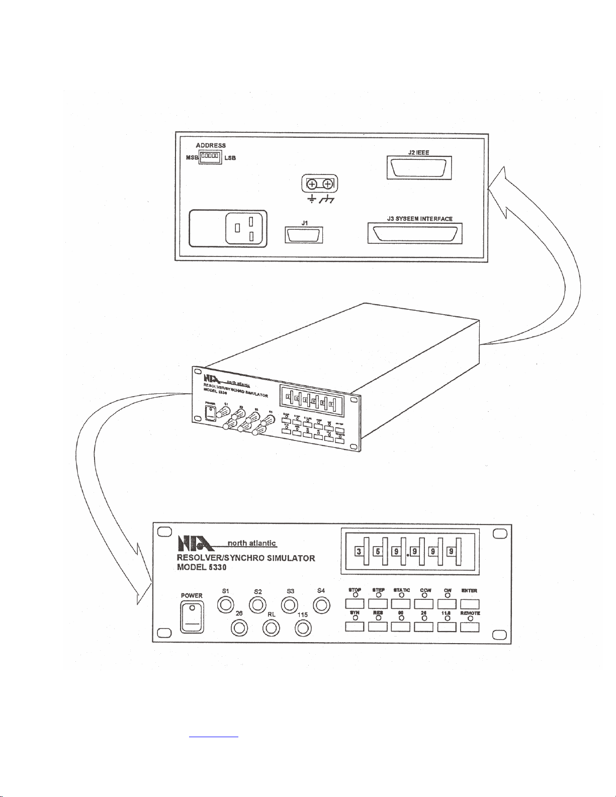
Front and Rear Views of Model 5330
North Atlantic Industries, Inc. .
631.567.1100/631.567.1823 (fax) 04-23-02
5330A001 Rev B1.0
170 Wilbur Place, Bohemia, NY 11716 www.naii.com / e-mail:[email protected] Cage Code: OVGU1 Page 7 of 8

North Atlantic Industries, Inc. .
631.567.1100/631.567.1823 (fax) 04-23-02
5330A001 Rev B1.0
170 Wilbur Place, Bohemia, NY 11716 www.naii.com / e-mail:[email protected] Cage Code: OVGU1 Page 8 of 8
Rack Mounting Adapter Accessories
Type of Mount Description NAI P/N
Full Rack Mounting Mounts one unit in 19-inch rack 783893
Tandem Full Rack Mounting Mounts two units side by side in 19-inch
rack (3-1/2-inch rack height) 548557
Tandem Full Rack Mounting Mounts two units side by side in 19-inch
rack (increases rack height to 7 inches) 787026
FEATURES AND OPTIONS
The Model 5330 is available with 2 standard options as shown below.
5330-F1 (Frequency Range 360Hz to 10 KHz)
5330-F2 (Frequency Range 47Hz to 1 KHz)
Custom solutions can be made to meet the needs of your application. Please contact [email protected] or

North Atlantic Industries, Inc. .
631.567.1100/631.567.1823 (fax) 04-23-02
5330A001 Rev B1.0
170 Wilbur Place, Bohemia, NY 11716 www.naii.com / e-mail:[email protected] Cage Code: OVGU1 Page 9 of 8
Revision History
Revision Change Made By Date Notes Approved
A Lou Garofolo 4-23-02 New Release LG
B1.0 Robert Skrepek 9-21-04 Released in support of ECO E39993
Table of contents
Popular Switch manuals by other brands


Sunricher
Sunricher SR-ZGP2801K4-5C instruction manual

DirekTronik
DirekTronik SX-SWE01B Operation manual

Link electronics
Link electronics 860-XL1616H Routing Switchers 860-XL1616H Specification sheet

Advantech
Advantech EKI-9516P-HV user manual

Cabletron Systems
Cabletron Systems 9E423-36 owner's manual

FOURSTEEL
FOURSTEEL MIMOO SWITCH installation instructions

Digi
Digi MIL-H3130 installation guide

Radio Shack
Radio Shack Amplified Video Selector owner's manual

Fujitsu Siemens Computers
Fujitsu Siemens Computers PRIMERGY BX600 user guide

Ruijie
Ruijie RG-ES05 Series Quick installation guide

Pathway connectivity solutions
Pathway connectivity solutions Pathport VIA12 User guide and manual

Targus
Targus USB-C user guide