North FG 6 Owner's manual

Technical instruction
Manual for use and maintenance
GAS CONVECTION OVENS
MODELS
FG 6 • FG 10
These appliances comply with requirements of E.C DIRECTIVE 2009/ 42/EC
SOTIRIOS D. PRODANAS G.P
PROFESSIONAL ELECTRIC & GAS MACHINES FOR RESTAURANT – PATISSERIES – SNACK BAR
OFFICE – FACTORY : National Road Kilkis-Thessaloniki – Tel ++30 23410 41819 – Fax ++30 23410 41539
P O Box 400 70, P C : 560 00 www north gr - e-mail : info@north,gr

1. PART I – INSTALLATION
We will present the essential data, technical characteristics and our advice for the correct installation,
use and maintenance of the appliances described. Let us remind you that the appliances are
professional use and that all procedures of installing, connecting to the distribution network and
positioning of the appliance in operation should be carried out by properly qualified personnel and that
all safety measures applicable in the country of installation should be observed.
The manufacturer cannot be held responsible for any possible damage to property, human
beings or animals that might be caused by misuse of the appliance or by using the appliance for
purposes other than those recommended for or not foreseen in this manual.
FIGURE 1: Technical Characteristics
Models Dimension (mm Trays
Dimen.
Trays
No. Burner TYPE
FG6 925 X 825 X 935(1235 60Χ40
GN1/1 6 INOX A
FG10 925 X 825 X
1270(1570
60Χ40
GN1/1 10 INOX A
Unit FG6 FG10
G 30 Main air regulation at 28…30 mbar (A) mm Open Open
G 20 Main air regulation at 20 mbar (A) mm 10 Open
G 30 Main air regulation at 50 mbar (A) mm Open Open
G 25 Main air regulation at 25 mbar (A) mm 10 Open
G 25 Main air regulation at 20 mbar (A) mm 10 Open
G 30 Main burner nozzle at 28…30 mbar mm 2.00 2.20
G 20 Main burner nozzle at 20 mbar mm 3.00 3.20
G 30 Main burner nozzle at 50 mbar mm 1.70 1.95
G 25 Main burner nozzle at 25 mbar mm 3.10 3.35
G 25 Main burner nozzle at 20 mbar mm 3.25 3.50
Main Ga Power kW 14 17
G30 Kg/h 1.104 1.341
G20 m³/h 1.481 1.799
Con umption
G25 m³/h 1.723 2.092
Calorie Kcal/h 12046 14627
Voltage Connection V - Hz 230 - 50 230 - 50
Electric Power Watt 550 800

FG6
835 257
780
390
1179
140
140O
740
942
517
800
1176
889
164
8 3 5
140O
400
5 5
942
800
100 110
295
400
70
8
9
0
O60
R 1/2"
151289
370 232340
222
64
80
502
144
O40
5
O40
5
155
GAS In l e t
Wat er I n l et
BURNER
1
5
R3/4"
R1/2"
1 – Water connection
5 – Ga connection

FG10
800
1
1
4
4
942
290
1064
780
390
85
502
750
1144
1064
146
1317
889
60O
517 68
R1/2"
R3/4"
400
800
155
71
GAS
H
2O
942
800
100 110
295
400
70
8
9
0
O60
R 1/2"
151289
370 232340
222
64
80
502
144
O40
5
O40
5
155
GAS In l e t
Wat er I n l et
BURNER
1
5
R3/4"
R1/2"
1 – Water connection
5 – Ga connection

1.1 Standards and Require ents
We would like to remind you that appliances installed in places open to the public should meet specific
requirements. Among them there are:
• Specific standards for the type of public place.
• Safety standards against fire and cause of panic in public place.
• General standards for the installation of cooking appliances in refreshment facilities.
• General standards concerning installation using combustible gas and liquid hydrocarbons.
• GENERAL WARNINGS
o Before you install and place in operation the appliance you carefully read the present
handbook that offers important information
o Keep the handbook carefully for future use for the operators or for case of after sale
o This appliance is intended for special industrial use and has been studied for the baking of
foods. Any other use is deemed improper.
o This appliance should be used by educated personnel and it is supervised at the duration of
operation
o Disconnect the appliance in case of damage or bad operation
o For repair you are addressed only in permitted centre of technical support of constructor and
require the placement of original parts
o The above instruction is for the safety and the correct function of the appliance not to cause
damages.
o Don't use for the cleaning of steel products that contain chloride even if they are dissolved
o Do not use corrosive substances in order to you clean the flooring under the appliance
1.2 Packing
Make sure packing is intact before removing the appliance. Open cardboard carefully to ensure no metal
stapling, adhesive tape or other packing components litter the environment, as these can prove hazardous.
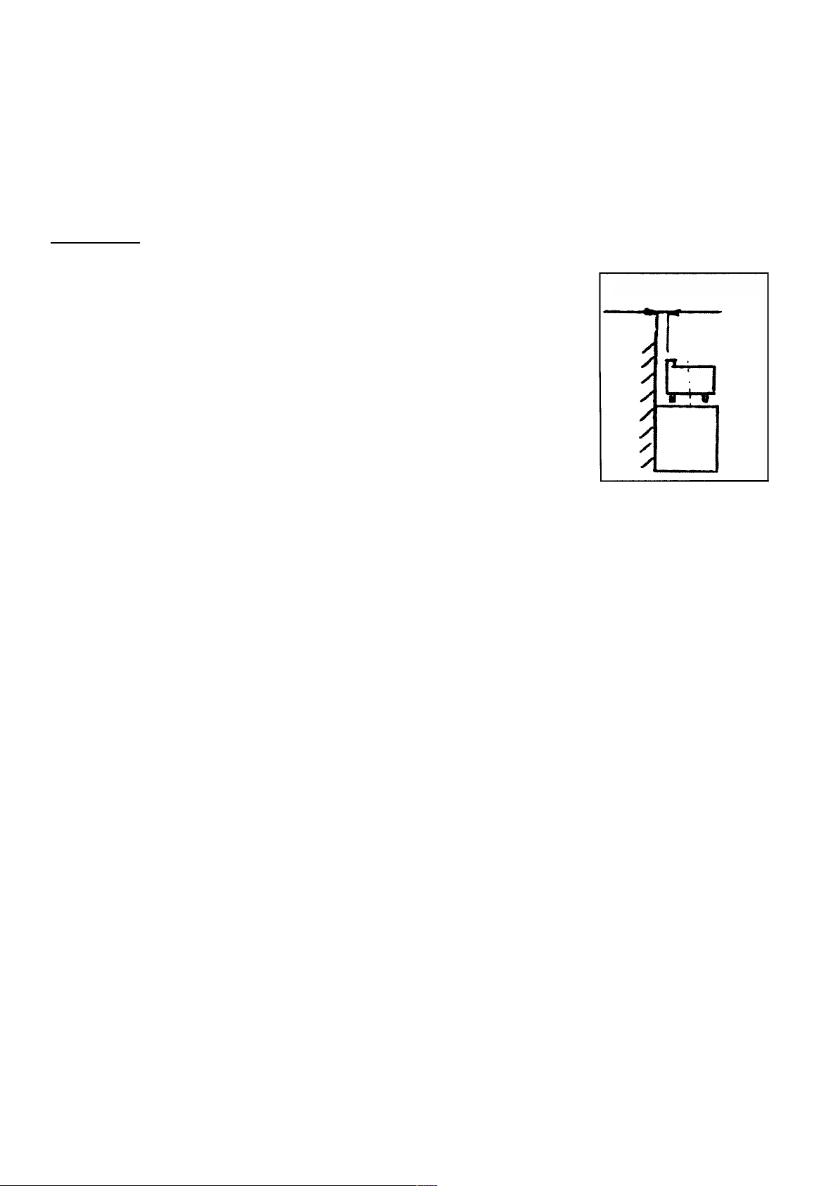
1.2 Obstacles and Position
Where this appliance is to be positioned in close proximity to a wall, partitions, kitchen furniture, decorative
finishes etc; it is recommended that they be made of non combustible material. If not, they should be clad
with a suitable non combustible heat insulating material, and that the closest attention be paid to Fire
Prevention Regulations
• Make sure there is enough space available for the placement of the appliance. Make sure that the
surface it stands on is stable and level.
• Remove the protective tape from the external parts of the appliance, making sure no glue or plastic
is stuck on the surface. If there are residues of glue, remove them using the right solvent.
• Make sure the appliance is level on the surface available. If necessary, regulate its height
accordingly, by adjusting the legs of the appliance.

1.4 Gas Connection
Before connecting the appliance to the network make sure that:
• The gas available it is the one the appliance is regulated for. If it is not, do not proceed with
connection. Regulate the appliance for the gas available following instructions under 2.2.
• Burners are manufactured to stand thermal and mechanical stress and are equipped with fixed
nozzles. This is why it is necessary to change the nozzles every time you change the type of gas.
• Data concerning the regulation of the appliance are to be found on the label of the right hand wall.
• Connect the appliance to the network using only metal piping, either rigid or flexible.
• Make sure the pressure used is the pressure the appliance is regulated for. In no case should
pressure exceed 50 mbar.
• Use the right sealing materials for all connections and check them for leaks.
• It is important for walls adjacent to appliance to be protected from the heat. Use refractory materials
or allow at least 200mm between the appliance and any adjacent walls (see figure below).
• Network connection should be made through a gate valve. This valve should be closed when the
appliance is not in operation.
1.4.1 Electric Connection
Mono phase connection is requiring for model FG6 & FG10.
Connect cable to a plug (Yellow – Earth / Blue – Neutral / Brown – Phase)
In case of bad connection there is possible not be function the appliance so please change the polarity.
WARNING: THIS APPLIANCE MUST BE ELECTRICALLY EARTHED.
1.4.2 Water Inlet Connection
The oven allocates entries of water.
On the right side of the machine under it you will find the inlet connection 3/4inch.
1.4.3 Water Outlet Connection
Connect drain fitting with a pipe o equal diameter and length from 0, 5 until 3 metres, and is resistant in
temperature at least 100°C. The drain pipe must be siphoned (height of 80 mm) to an open drain the "("Air
break") or floor grating in order to prevent any back flow from the sewage system from reaching the piping
inside the oven or over chamber.
Make sure that pipes are straight (minimal bent 5%).
Attention: The drain system must be installed so that any vapours from the open drain do not enter the
aeration vents under the appliance.

1.5 Combustion Products
Appliances should be installed in places appropriate for the removal of fumes according to installation
specifications. Our appliances are classified as gas type A.
Such appliances must send fumes into appropriate air extractors connected to safe and effective pipes that
direct them outdoors.
! CAUTION !
Appliances must always be positioned below 200 mm ON THREE SIDES an
air extractor, which directs fumes outdoors.
Appliances with an overall thermal power exceeding 14 Kw must be installed
below an air extractor with a switch and pilot for the gas supply system.
Specifically, the supply circuit electric valve at the top
of the appliance must be switched off.
Make sure there are set by installation standard UNI CIG 8723,
point 4.3 ‘’Removal of combustion products’’.
Indicatively, the air extractor must guarantee aspiration power
equivalent to 2m³/h for every Kw of thermal
power provided.
Pipes to collect fumes from the appliances and direct them to
a single air extractor point can be provided at your request.
In this case, too, the appliance must be placed under an
air extractor.
mm 200 on 3 side
Adequate ventilation is essential for safe operation of a gas appliance. A supply of fresh air is necessary for
the correct combustion of the gas and there must be a means of exhausting the heat and the products of
combustion from the kitchen. It is recommended that the appliance be sited below a ventilating hood, one
preferably connected to an extractor system incorporating a grease filter.
These appliances are to be installed with sufficient ventilation to prevent the occurrence of unacceptable
concentrations of substances harmful to health in the room in which they are installed.
The appliance MUST NOT be connected DIRECTLY to a flue or ventilating system, although the flue
products of two or more appliances may be directed into a common outlet when building suite of
appliances

2. OPERATION
The appliance operates under normal power with the nozzles mentioned above (see Table of Figure 1).
Supply pressure must correspond to the value mentioned in the relevant data table.
2.1 Pressure Control
In order to measure the supply pressure, you need a liquid manometer with a minimum sub division of 0,1
mbar (eg a U shaped pressure gauge).
Follow this procedure:
• Remove the appliance to regulate the opening to be found behind.
• Unscrew the screw shutting the pressure valve.
• Connect the manometer and measure the pressure. (See values indicated in Fig.1)
• Remove manometer, re screw the screw and make sure there are no leaks.
2.2 Regulation or operation with di erent gases
Both the packaging and the appliance carry the regulation data for suitable gases. If regulation is
necessary for another type of gas, you should:
a) Make sure which type of gas and pressure correspond to the values mentioned in the relevant data
table.
b) Choose the right nozzle for the specific type of gas and the pressure available in place, keeping in
mind data included of this manual (keep in mind that pressure should never exceed 50 mbar) and
replace nozzle, if necessary.
2.3 Main burner regulation
• Replace nozzle by unscrewing it and screwing the one appropriate for the type of gas.
• Regulate main air supply through the regulating ring, adjusting distance A as seen on the Table of
Figure 1.
• In order to regulate the flow of the main air supply, unscrew place ring in desirable position and
screw the screw back on until shut.
• To make sure the regulation of the main air supply is the right one, see that no flames break away
from the burner when it is cold and there is no flame going back into the nozzle
• when the burner is hot.
!!! ATTENTION !!!
Please stick the correct label of gas type which you are adjust the achine
40
A

2.4 Operation Control
• Check that the appliance is level on the supporting surface.
• Make sure there is a good clean air inflow.
• Make sure there are no leaks or loss of gas.
• Set the appliance in operation.
• Check flame stability of both the main and the pilot burner.
• Make sure non combusted gases have an appropriate outlet.
2.5 Interventions, repairs and replacements
( or authorized technicians only)
Even if the appliance is used correctly, some problems may arise for various reasons. The table that
follows mentions some possible problems and some suggestions to put them right.
! CAUTION !
• Before any intervention for maintenance, repairs or simple cleaning of the appliance, you must shut
the gas and electric supply.
• At the end of any intervention for maintenance or repairs to some parts the appliance related to gas,
check for air tightness and make sure there are no leaks or losses.
FIGURE 3 Possible Problems
PROBLEM POSSIBLE EXPLANATION
Ga mell Po ible ga lo :
Check external pipe and connection
Smell of non-burned ga
Check that combu tion i proper / Check that ga
con umption i not exce ive / Check that hot
fume circuit i not ob tructed / Check that air-
extractor and area ventilation are operating
property
‘’Explo ion ’’ in the burner
Check ga pre ure.
Make ure the pilot burner flame i not too far from
the main burner
The main burner doe not light
Check there i a leak in the ga upply pipe or any
problem with the nozzle / The burner part may be
improperly placed / Check the po ition of the pilot
burner
The main burner doe not light Change the polarity of the electrical plug.

3.PART III – For the user
3.1 Operation – General Precautions
We would like to remind you that these appliances are designed exclusively for professional use and
must be operated by qualifies people.
In order to set the appliance into operation, observe meticulously everything included in these pages as
well as ordinary safety measures:
• Make sure there is no gas leak.
• Check that the burner lights properly along its full length.
• Make sure there is a good inflow of clean air.
Before you place in operation the appliance it is necessary a qualify technician has to install it.
Instruction contain constitute important source of information on the right and sure use of oven. In case
where you need more information regarding the characteristics and cooking performance, consult your
dealer.
• Don't place pans or tools on top of the oven in order to avoid the obstruction of fumes and steams.
• Periodically (at least once per year), total control of appliance. Door flange – Thermostat – Safety
thermostat – Ignitor – Light – Timer – Water tap. .
• Placing the foods in the chamber, for best result you must leave a space at least 40mm between
the trays in order for better circulation of hot air.
• For best result you must preheat the oven before you start cooking.
• At the duration of operation, is prohibited the placement of flammable liquids, eg alcoholic, in the
oven chamber.
3.2 Start on
Make sure there is no any plastic, cartoon or any material which may be easy get in fire are inside the
chamber
• Turn on the timer knob right at the desire position (0 120min) or at the manual position ( ∞ )
(for manual turn the knob left)
• Turn the knob of the temperature right side to enter the desire temperature 50 300Cº
The motor of the oven will start and the light will turn on in the chamber.
If the motor did not start check if the door is closed.
In case the indicate light of the RESET button turn on the oven has not start, retry by pressing the reset
button.
In case can not turn on please change the polarity of the electric plug and retry if still not start on the
oven contact with authorized technician.
3.3 Water Spray
Turn the knob of the water spray at your desire position from 1 (min) to 6 (max).
Make sure the connection of the water is correct and the water tap is on.

3.4 CLEANING AND MAINTENANCE
Turn off the oven before any cleaning or maintenance procedures. Let the appliance cool.
- In the end of each day you must clean the chamber of oven using the suitable products and following
the directives of supplier.
- Don't wash the appliance with direct of water external.
- Don't use for the cleaning of steel products that contain chlorine (bleach, hydrochloric acid etc), even if
they are dissolved.
- Do not use corrosive substances (for example muriatic' acid) in order to you clean the flooring under
the appliance.
!!! WARNING !!!
While the oven are in unction be very care ully while you open the door because the oven chamber
is hot and it is dangerous or getting burn.
Timer
Temperature
Humidity Spray
Reset
This manual suits for next models
1
Table of contents
Other North Oven manuals
Popular Oven manuals by other brands

Waldorf
Waldorf RN8510GE Operation manual

KitchenAid
KitchenAid KEHU309SSS - 30" Microwave Combination Oven datasheet

Frigidaire
Frigidaire PLEB27T9D Factory parts catalog

Monogram
Monogram ZTD90DSSNSS owner's manual

Zanussi
Zanussi FBI 553 B Instructions for use and care

Stirling
Stirling SO69S instruction manual

Pelgrim
Pelgrim OKW740RVS Instructions for use

Bosch
Bosch HBA534E.0K User manual and installation instructiions

Nouvel
Nouvel 402000 Instructions for use

Fisher & Paykel
Fisher & Paykel EB60 installation guide

Whirlpool
Whirlpool W7 OM5 4S P Daily reference guide

Electrolux
Electrolux EOG 600 Instruction booklet