Northen CENTURION Series User manual

NORTHERN ELECTRIC PRACTICES SECTION 506-3241-200·
Issued: 18 April 1974
Standard
"CENTURION*"
-
COIN
TELEPHONE
SETS
QSD400A1 AND QSD2400A1
IDENTIFICATION AND INSTALLATION
(a) QSD400Al (b) QSD2400A1
Fig. 1 -
Front
View
of
QSD400Al and QSD2400Al CoinTelephone Sets
*A trademark
of
Northern Electric.
©Northern Electric Company Limited, 1974
PRINTED IN CANADA Page 1
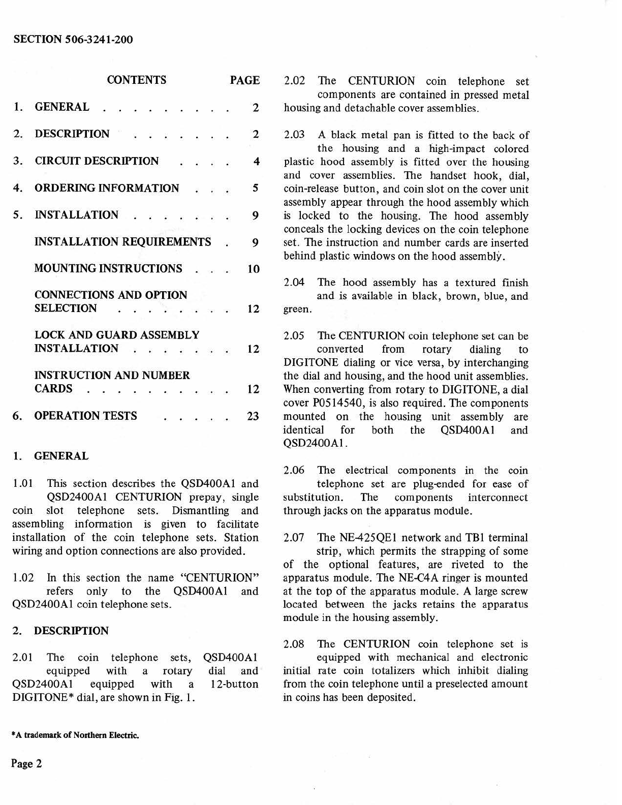
SECTION 506-3241-200
CONTENTS
1.
GENERAL
2. DESCRIPTION
3. CIRCUIT DESCRIPTION
4. ORDERING INFORMATION
5. INSTALLATION
INSTALLATION REQUIREMENTS
MOUNTING INSTRUCTIONS
CONNECTIONS AND OPTION
PAGE
2
2
4
5
9
9
10
2.02 The CENTURION coin telephone set
components are contained in pressed metal
housing and detachable cover assemblies.
2.03 A black metal pan
is
fitted
to
the back
of
the housing and a high-impact colored
plastic hood assembly is fitted over the housing
and cover assemblies. The handset hook, dial,
coin-release button, and coin slot on the cover unit
assembly appear through the hood assembly which
is
locked to the housing. The hood assembly
concea
ls
the locking devices on the coin telephone
set. The instruction and number cards are inserted
behind plastic windows on the hood assembly.
2.04 The hood assembly has a textured finish
and is available in black, brown, blue, and
SELECTION 12 green.
WCK
AND GUARD ASSEMBLY 2.05 The CENTURION coin telephone set can
be
INSTALLATION 12 converted from rotary dialing to
INSTRUCTION AND NUMBER DIGITONE dialing or vice versa, by interchanging
the dial and housing, and the hood unit assemblies.
CARDS 12
When
converting from rotary to DIGITONE, a dial
cover P0514540,
is
also required. The components
6. OPERATION TESTS 23 mounted
on
the housing unit assembly are
1.
GENERAL
1.
01 This section describes the QSD400Al and
QSD2400Al CENTURION prepay,
si
ngle
coin slot telephone sets. Dismantling and
assembling information
is
given
to
facilitate
installation
of
the coin telephone sets. Station
wiring and option connections are also provided.
1.02 In this section the name "CENTURION"
refers only
to
the QSD400Al and
QSD2400Al coin telephone sets.
2. DESCRIPTION
2.01 The coin telephone sets,
equipped with a rotary
QSD2400Al equipped with a
DIGITONE* dial, are shown in Fig.
1.
•A
tradem~k
of
Northern Electric.
Page 2
QSD400Al
dial and
12-button
identical for both the QSD400Al and
QSD2400Al.
2.06 The electrical components in the coin
telephone set are plug-ended for ease
of
substitution. The components interconnect
through jacks on the apparatus module.
2.07 The NE-425QE1 network and TBl terminal
strip, which permits the strapping
of
some
of
the optional features, are riveted
to
the
apparatus module. The NE-C4A ringer is mounted
at the
top
of
the apparatus module. A large screw
located between the jacks retains the apparatus
module in the housing assembly.
2.08 The CENTURION coin telephone set
is
equipped w
it
h mechanical and electronic
initial rate coin totalizers which inhibit dialing
from the coin telephone until a preselected amount
in coi
ns
has been deposited.

2.09 When shipped from the factory the
CENTURION sets are arranged
to
operate
on
the
mechanical totalizer
at
a 10-cent initial rate.
With this arrangement the set
may
be used
on
either ground-start
or
loop-start Central Office
(CO) lines.
2.10
Th
e electrical Variable Initial Rate (VIR)
totalizer
on
the Printed Circuit
Bo
ard (PCB)
assembly in the coin telephone set can be modified
to
change
the
initial
rate
from 5-cents through
40-cents in increments
of
5-cents.
2.1
1 The Free Access
to
Selected Numbers
(F
ASN) fea
tur
e permits coinless calling
to
special preselected numbers. The
CO
must
be
equipped for FASN and the line must have a
loop-start line circuit.
2.12 Ground Isolation (GI) disconnects the
grounding circuit from the transmission
path
to
minimize line induced noise during voice
transmission. This feature requires
that
the
CO line
is equipped with a loop-start line circuit.
2.13 The coin identification signals are
transmitted
to
the
operator by a solid state
tone
generator when the required coins are
deposited in the coin telephone set.
2.14 The transmission qualities
of
the
CENTURION coin telephone sets are
similar
to
those
of
the
NE-500
type
telephone set.
2.15
The
maximum loop resistance for
satisfactory operation
of
the
set is
determined by such parameters
as
minimum CO
battery voltage, feeding bridge resistance, ringing
cut-off current, etc.
To
ensure reliable operation
it
is
recommended
that
the
following conditions be
met.
(a) With
the
handset off-hook the de voltage
at
the
ring and tip terminals
of
the
set must
not
be less
than
4.4 vo
lt
s.
(b) The current in
the
ring side
of
the line
should
not
be less
than
23.0 milliamperes
with the hopper trigger switch in
the
normal
position (i.e.,
not
tripped).
SECTION 506-3241-200
Example
of
long loop:
CO battery
Resistance
Current
45.0 volts
200 ohms X 200 ohms
23.0 milliamperes
1
365
ohmsLoop resistance
2.16
Note: Other factors associated with the CO
may limit the loop resistance
to
less
than
1365 ohms.
For
higher loop resistance a long
line circuit should be used.
The coin telephone
set
weighs
approx
im
ate
ly 50 pounds (22.7 kilograms).
2.17 The dimensions
of
the
CENTURION coin
telephone
set
are shown in Fig. 2.
1
~
9.2 IN
..
---~
Fig. 2 - Rear View
of
CENTURION Coin
Telephone
Set
Page 3
SECTION 506-3241-200
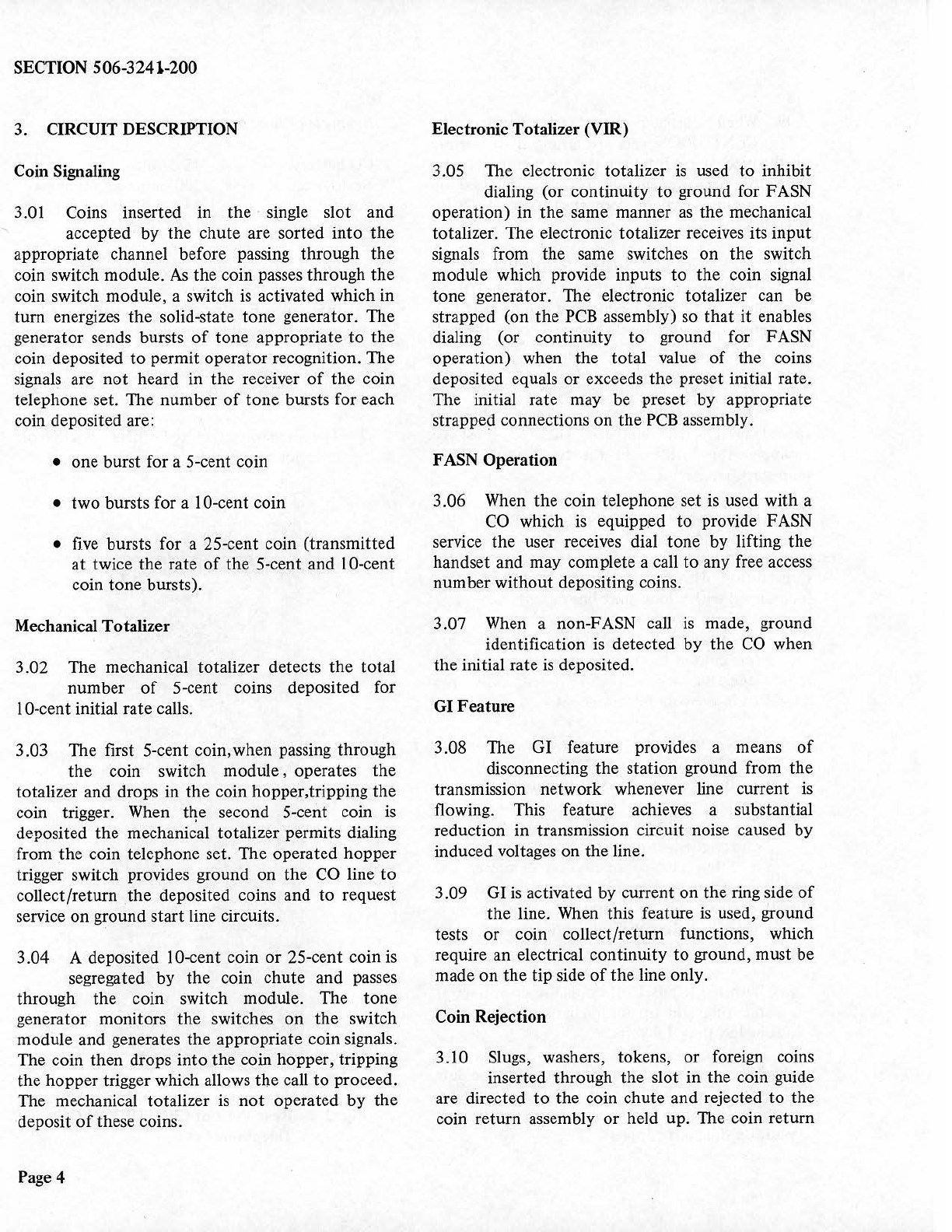
3. CIRCUIT DESCRIPTION
Coin Signaling
3.01 Coins inserted in the · single slot and
accepted by the chute are sorted into the
appropriate channel before passing through the
coin switch module.
As
the coin passes through the
coin switch module, a switch is activated which in
tum
energizes the solid-state tone generator. The
generator sends bursts
of
tone appropriate
to
the
coin deposited
to
permit operator recognition. The
signal~
are
not
heard in the receiver
of
the coin
telephone set. The number
of
tone bursts for each
coin deposited are:
• one burst for a 5-cent coin
• two bursts for a 10-cent coin
•
five
bursts for a 25-cent coin (transmitted
at
twice the rate
of
the 5-cent and 10-cent
coin tone bursts).
Mechanical Totalizer
3.02 The mechanical totalizer detects the total
number
of
5-cent coins deposited for
10-cent initial rate calls.
3.03 The first 5-cent coin,when passing through
the coin switch module, operates the
totalizer and drops in the coin hopper,tripping the
coin trigger. When tqe second 5-cent coin
is
deposited the mechanical totalizer permits dialing
from the coin telephone set. The operated hopper
trigger switch provides ground on
the
CO line
to
collect/return the deposited coins and
to
request
service on ground startline circuits.
3.04 A deposited 10-cent coin
or
25-cent coin
is
segregated by the coin chute and passes
through the coin switch module. The tone
generator monitors the switches
on
the switch
module and generates the appropriate coin signals.
The coin then drops into the coin hopper, tripping
the hopper trigger which allows the ca
ll
to
proceed.
The mechanical totalizer
is
not
operated by the
deposit
of
these coins.
Page4
Electronic Totalizer (VIR)
3.05 The electronic totalizer
is
used
to
inhibit
dialing (or continuity
to
ground for FASN
operation) in the same manner
as
the mechanical
totalizer. The electronic totalizer receives its input
signals from the same switches on the switch
module which provide inputs
to
the
coin signal
tone generator. The electronic totalizer can be
strapped (on the
PCB
assembly) so
that
it
enables
dialing (or continuity
to
ground for F
ASN
operation) when the total value
of
the coins
deposited equals
or
exceeds the preset initial rate.
The initial rate may be preset by appropriate
strapped connections on the
PCB
assembly.
F
ASN
Operation
3.06
When
the coin telephone set is used with a
CO
which
is
equipp.ed
to
provide F
ASN
service the user receives dial tone by lifting the
handset and may complete a call
to
any free access
number without depositing coins.
3.07
When
a non-FASN call
is
made, ground
identification is detected by the
CO
when
the initial rate
is
deposited.
GI Feature
3.08 The GI feature provides a means
of
disconnecting the station ground from the
transmission network whenever line current
is
flowing. This feature achieves a substantial
reduction in transmission circuit noise caused by
induced voltages on
th
e line.
3.09
GI
is activated by current on the ring side
of
the line.
When
this feature is used, ground
tests
or
coin collect/return functions, which
require an electrical continuity
to
ground, must be
made on the tip side
of
the line only.
Coin Rejection
3.10 Slugs, washers, tokens, or foreign coins
inserted through the slot in the coin guide
are directed
to
the coin chute and rejected
to
the
coin return assembly
or
held up. The coin return
button,
when pressed, has a positive clearing
action, which releases
the
slugs, washers, etc.,
into
the
coin
return
assembly.
4.
ORDERING
INFORMATION
4.01
The
CENTURION coin telephone sets are
.
ordered
as follows:
COIN TELEPHONE SET
QSD400Al
COIN TELEPHONE SET
QSD2400Al
The
color suffix shown in Table A follows
the
coin
telephone set code number.
TABLEA
COLOR
SUFFIX
NUMBER
SUFFIX
COLOR NUMBER
Black -03
Brown -26
Blue -27
Green -28
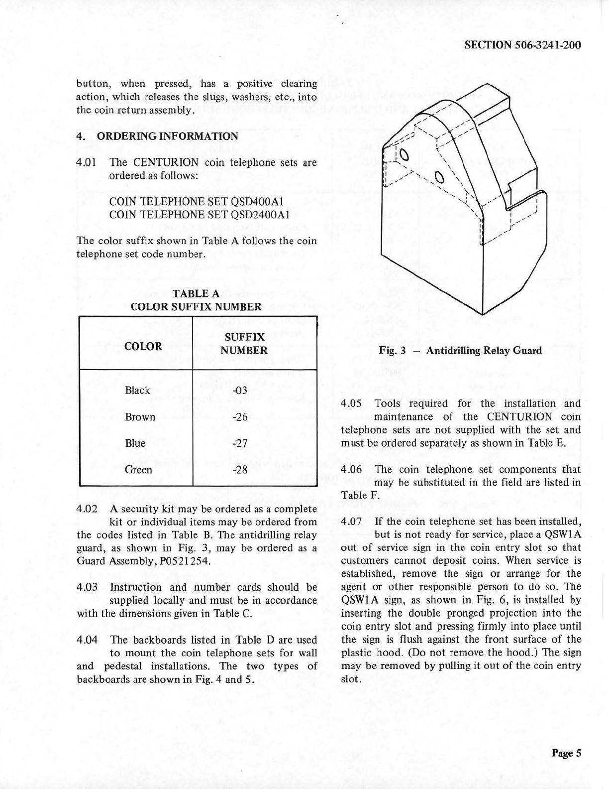
4.02
A security
kit
may
be
ordered
as a
complete
kit
or
individual
items
may
be ordered from
the
codes listed in Table
B.
The
antidrilling relay
guard, as
shown
in Fig.
3,
may be
ordered
as a
Guard Assembly,
P0521254.
4.03 Instruction
and
number
cards should be
supplied locally
and
must
be in accordance
with
the
dimensions given
in
Table
C.
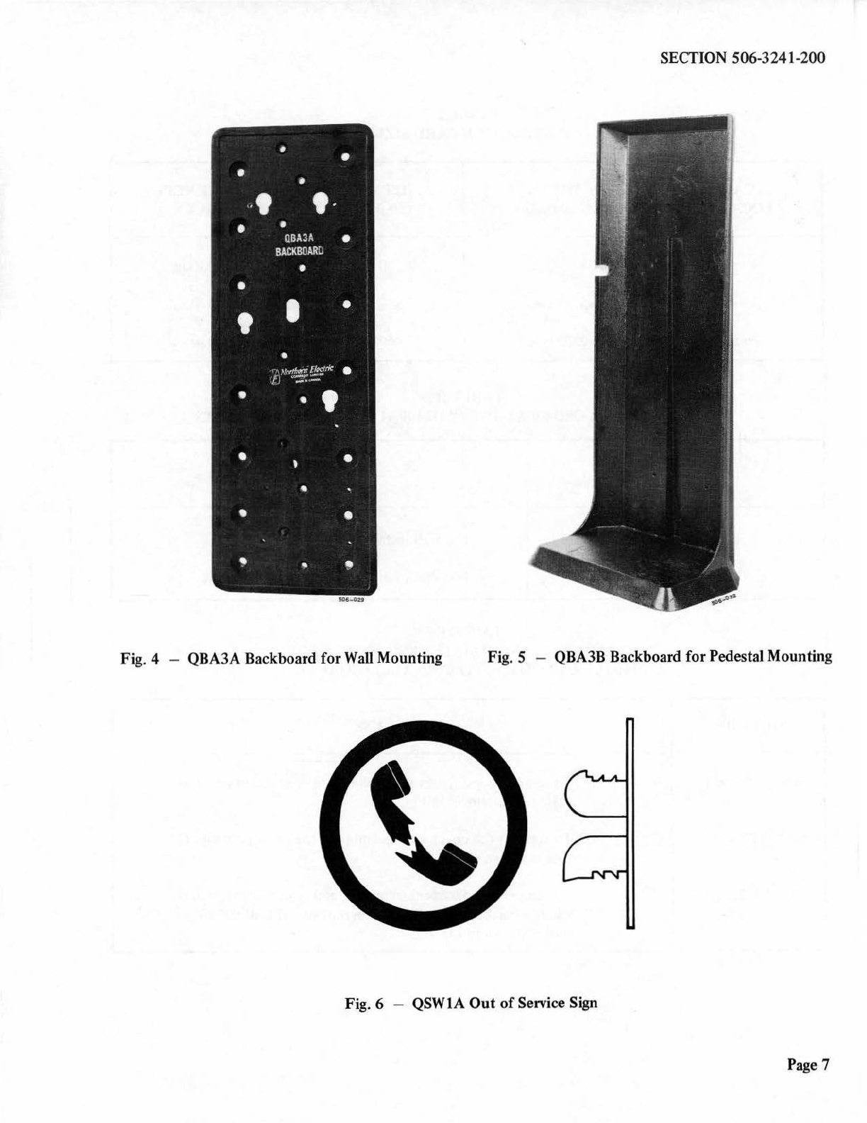
4.04
The
backboards listed
in
Table D are used
to
mount
the
coin telephone sets
for
wall
and
pedestal installations.
The
two
types
of
backboards are
shown
in
Fig. 4 and 5.
SECTION 506-3241-200
Fig. 3 - Antidrilling Relay Guard
4.05 Tools required for
the
installation and
maintenance
of
the
CENTURION coin
telephone sets are
not
supplied with
the
set
and
must
be ordered separately
as
shown in Table E.
4.06
The
co
in
telephone set
components
that
may
be
substituted in
the
field a
re
listed in
Table
F.
4.07
If
the
coin telephone
set
has been installed,
but
is
not
ready
for
service, place a QSWl A
out
of
service sign in
the
coin
entry
slot
so
that
customers
cannot
deposit coins. When service is
established, remove
the
sign
or
arrange for
the
agent
or
other
responsible person
to
do
so.
The
QSWl A sign, as
shown
in Fig.
6,
is install
ed
by
inserting
the
double
pronged projection
into
the
coin
entry
slot and pressing firmly
into
place until
the
sign is flush against
the
front
surface
of
the
plastic hood. (Do
not
remove
the
hood.)
The sign
may
be
removed
by
pulling
it
out
of
the
coin
entry
slot.
Page 5

SECTION 506-3241-200
Page6
TABLEB
SECURITY KITS AND SEPARATELY ORDERED ITEMS
FOR
QSD400Al AND QSD2400Al COIN TELEPHONE SETS
KIT ITEM ITEM
DESIGNATION CODE DESCRIPTION
CODE
NE-22QC Cash compartment lock with 2 keys
QKBIB NE-22QD Cover unit assembly lock (Note 1)
Security Kit NE-IB Standard-size cash receptacle
NE-IC Receptacle cover
POI
5E388 Spacer and spring assembly
NE-22QC Cash compartment lock with'2 keys
QKB2B NE-22QD Cover unit assembly lock (Note
I)
Security Kit NE-IC Oversize cash receptacle
NE-IC Receptacle cover
P010E070 Mounting studs (4 required)
Accessory P0521254 Guard assembly
Equipment -Key for NE-22QD lock
-Reserved lock combination (Note
2)
Notes:
I.
Keys for
the
NE-22QD lock are
not
supplied with the lock and must
be
ordered separately
in
the
quantity required.
2. Security kits are available with reserved lock combinations for
the
NE-22QD
lock,
on
a special order basis.
SECTION 506-3241-200
506-0U
Fig. 4 - QBA3A Backboard
for
Wall Mounting Fig. 5 -QBA3B Backboard for Pedestal Mounting
Fig. 6 - QSWlA
Out
of
Service Sign
Page 7
SECTION 506-3241-200
CARD
LOCATION
Upper
Lower
Number
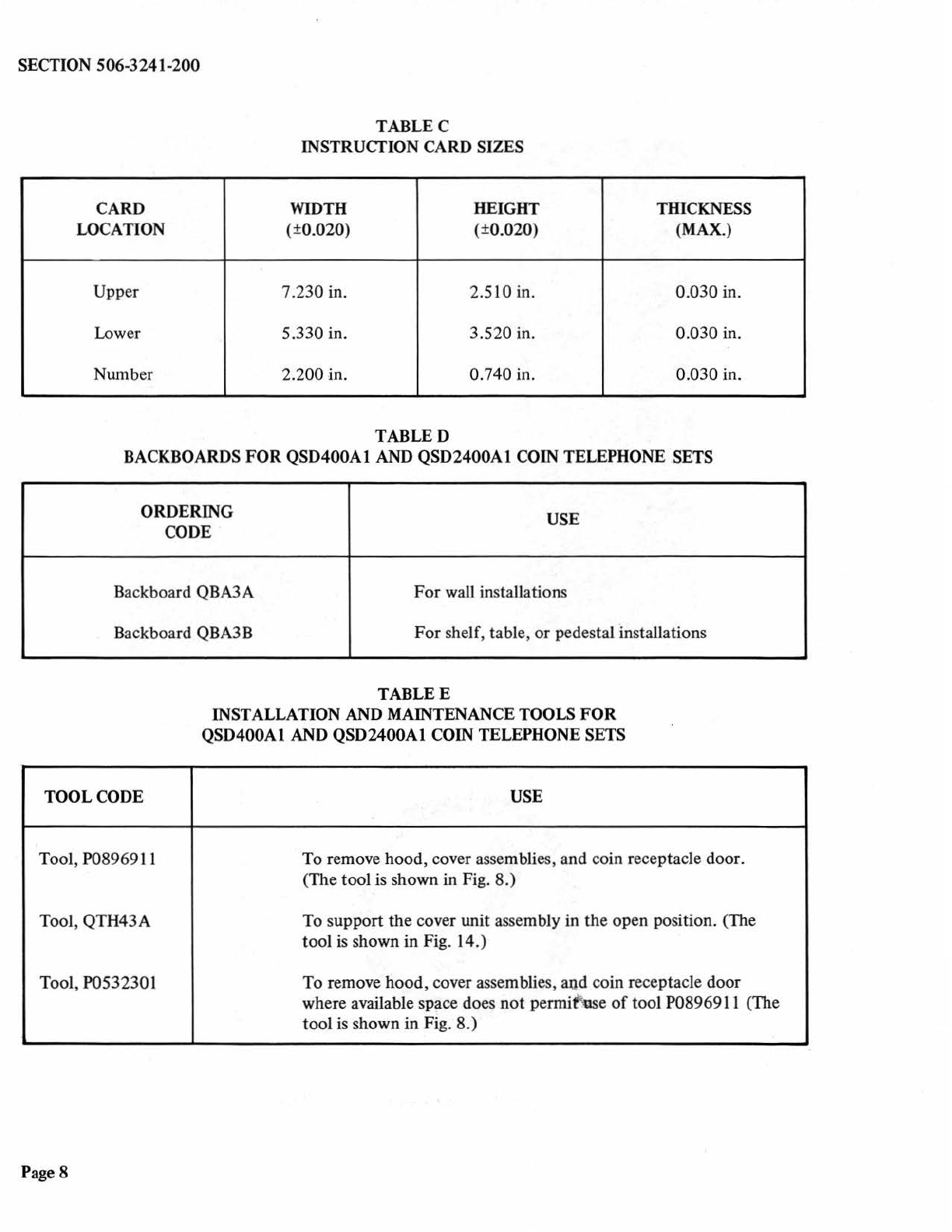
TABLEC
INSTRUCTION CARD SIZES
WIDTH HEIGHT
(±0.020) (±0.020)
7.230 in. 2.510 in.
5.330 in. 3.520 in.
2.200
in.
0.740 in.
TABLED
THICK.NESS
(MAX.)
0.030 in.
0.030 in.
0.030 in.
BACKBOARDS
FOR
QSD400Al AND QSD2400Al COIN TELEPHONE SETS
ORDERING
CODE USE
Backboard QBA3A
For
wall installations
Backboard QBA3B
For
shelf, table,
or
pedestal installations
TABLEE
INSTALLATION AND MAINTENANCE TOOLS
FOR
QSD400A1 AND QSD2400A1 COIN TELEPHONE SETS
TOOL CODE USE
Tool, P08969l 1 To remove
hood
, cover assemblies, and coin receptacle door.
(The tool is shown in Fig. 8.)
Tool, QTH43A To s
upport
the
cover unit assembly in
the
open position. (The
tool is shown in Fig. 14.)
Tool, P0532301 To remove
hood,
cover assemblies, aud coin receptacle door
where available space does
not
permif
'\lSe
of
tool P08969l l (The
tool
is
shown
in
Fig.
8.)
Page8
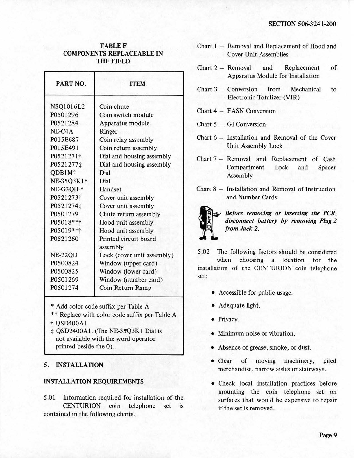
TABLEF
COMPONENTS REPLACEABLE IN
THE FIELD
PART NO. ITEM
NSQ1016L2 Coin chute
P0501296 Coin switch module
P0521284 Apparatus module
NE-C4A Ringer
P015E687 Coin relay assembly
P015E491 Coin return assembly
P052127lt
Dial and housing assembly
P0521277+ Dial and housing assembly
QDB
l
Mt
Dial
NE-35Q3Kl+ Dial
NE-G3QH-*. Handset
P0521273t
Cover unit assembly
P0521274+ Cover unit assembly
P0501279 Chute return asse
mb
ly
P05018**t
Hood unit assembly
P05019**t Hood unit assembly
P0521260 Printed circuit board
assembly
NE-22QD Lock (cover unit assembly)
P0500824 Window (upper card)
P0500825 Window (lower card)
P0501269 Window (number card)
i>oso1274 Coin Return Ramp
* Add color code suffix per Table A
** Replace with color code suffix per Table A
t QSD400Al
+ QSD2400Al. (The
NE-3~3Kl
Dial
is
not
available with
the
word operator
printed beside
the
0).
5.
INSTALLATION
INSTALLATION REQUIREMENTS
5.01 Information required for installation
of
the
CENTURION coin telephone set
is
contained in
the
following charts.
SECTION 506-3241-
200
Chart l - Removal and Replacement
of
Hood and
Cover Unit Assemblies
Chart 2 - Removal and Replacement
of
Apparatus Module for Installation
Chart 3 - Conversion from Mechanical
to
Electronic Totalizer (VIR)
Chart 4 - FASN Conversion
Chart 5 - GI Conversion
Chart 6 - Installation and Removal
of
the Cover
Unit Assembly Lock
Chart 7 - Removal and Replacement
of
Cash
Compartment Lock and Spacer
Assembly
Chart 8 - Installation and Removal
of
Instruction
and Number Cards
ftBefore removing or inserting the
PCB,
disconnect battery
by
removing
Plug
2
from Jack 2.
5.02 The following factors should
be
considered
when choosing a location for the
installation
of
the CENTURION coin telephone
set:
• Accessible for public usage.
• Adequate light.
• Privacy.
• Minimum noise or vibration.
• Absence
of
grease, smoke, or dust.
• Clear
of
moving machinery, piled
merchandise, narrow aisles or stairways.
• Check local installation practices before
mounting
the
coin telephone set on
surfaces
that
would be expensive to repair
if
the
set is removed.
Page9
SECTION 506-3241-200
• Telephone and wiring must be located
at
least 6 inches from neon light fixtures,
transformers or other equipment likely to
cause inductive effects.
• The CENTURION coin telephone set must
be mounted on a vertical surface. A tilt
greater than 1.5 degrees in any direction
can cause chute malfunction.
MOUNTING INSTRUCTIONS
5.03 For wall mounted installations, the
CENTURION coin telephone set is
mounted with a QBA3A backboard
as
follows:
(a) Place a mark
on
the wall 63 inches from the
floor
ff
the user
is
standing, or 52 inches
from the floor
if
the user
is
seated.
(b) Place the station 3-conductor wiring through
the wiring access hole
of
the backboard.
(c) Select the appropriate type
of
fasteners
from Table G.
(d) Locate
top
edge
of
the backboard on the
mark
on
the mounting surface and secure
with one fastener.
(e)
Move
the backboard
to
the vertical position
and mark the position.
(f) Place the remammg fasteners in the
backboard. Place sufficient fasteners
to
guarantee security.
Note: A spirit level may be used to ascertain
if the wall
is
vertical and
to
mount the
telephone set in the vertical position.
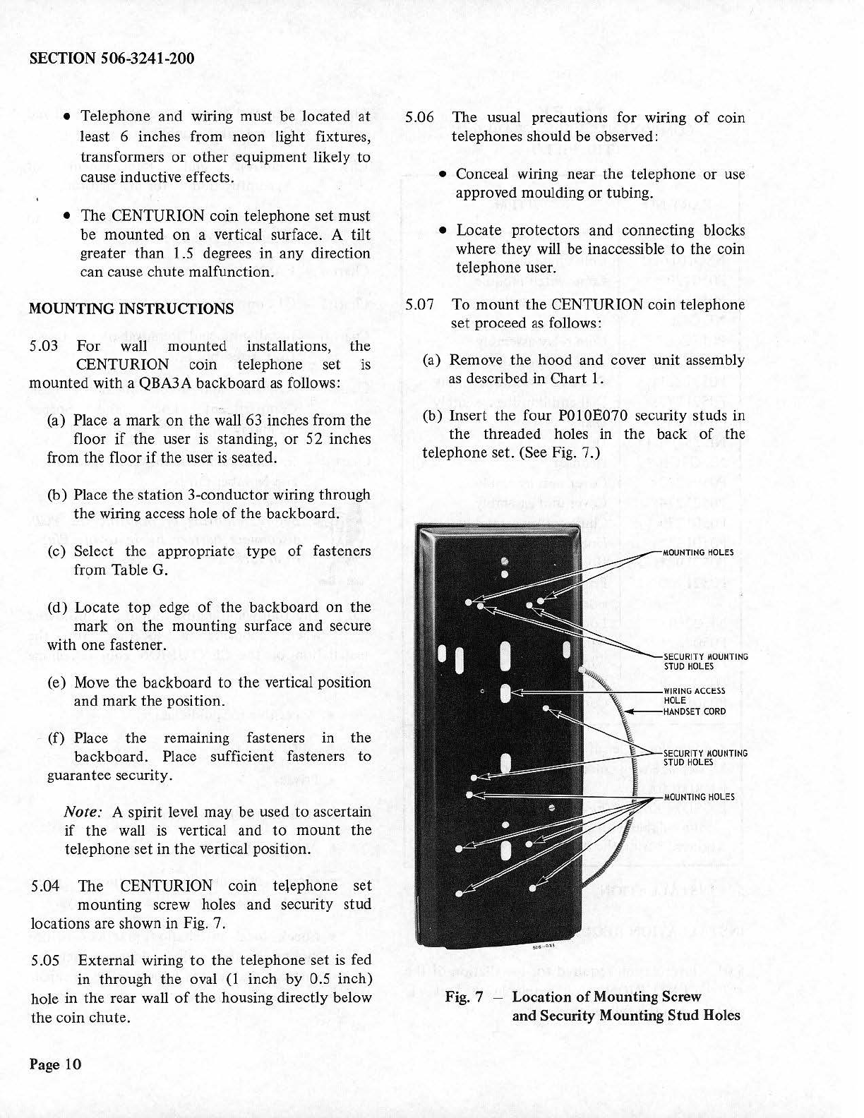
5.04 The CENTURION coin telephone
set
mounting screw holes and security stud
locations are shown in Fig. 7.
5.05 External wiring
to
the telephone set
is
fed
in through the oval
(1
inch by 0.5 inch)
hole in the rear wall
of
the housing directly below
the coin chute.
Page 10
5.06 The usual precautions for wiring
of
coin
telephones should be observed:
• Conceal wiring near the telephone
or
use
approved moulding or tubing.
• Locate protectors and connecting blocks
where they will
be
inaccessible
to
the coin
telephone user.
5.07
To
mount the CENTURION coin telephone
set proceed
as
follows:
(a) Remove the hood and cover unit assembly
as
described in Chart
I.
(b) Inse
rt
the four
PO
IOE070 security studs in
the threaded holes in the back
of
the
telephone set. (See Fig. 7.)
MOUNTING
HOLES
SECURITY
MOUNTING
STUD
HOLES
Fig. 7 - Location
of
Mounting Screw
and Security Mounting
Stud
Holes

(c) Inse
rt
the 3-conductor station wire through
the
wiring access hole in
the
coin telephone
set housing.
SECTION 506-3241-200
(d) Engage the security s
tu
ds
at
the back
of
the
set in
the
keyhole slots in the backboard and
allow
the
set
to
slide down
into
position.
TABLEG
FASTENERS FOR COIN TELEPHONE SET
BACKBOARDS
MOUNTING HOLE SIZE SIZE AND
MINIMUM
SURFACE REQUIRED TYPE
OF
NUMBER
FASTENERS
OFF
ASTENERS
Softwood I/8-inch 1-3/4 inch 7
or
No.
14
FH
No.
30'
wood screw
Hardwood 1/8-inch
1-1
/4
inch 7
or
No. 14
FH
No.
30
wood screw
Masonry 5/16-inch 2 inch 7
Concrete No. 14 FH
Brick wood screw
in No. 16 plas-
tic anchor
Cinder Block 3/4-inch 1/4 x 4 inch 6
Hollow Tile RH toggle
bolt
Note: Additional fasteners may
be
used
to
ensure securi
ty.
(e) Remove
the
apparatus module as described
in Chart 2.
(f)
Remove
the
PCB assembly
by
grasping the
upper a
nd
lower corners
of
the circuit
board
and pulling forward.
(g) Fasten
the
set
to
the
backboard with three
pan-head machine screws
(I
/4
inch, no.
20)
1
/2
inch in length.
(h)
Insert four pan-head machine screws at the
back
of
the
coin receptacle,
if
accessible.
(i) Place the apparatus module as described
in
Chart
2.
(j)
Insert the P
CB
assembly a
ft
er checking
that
it
is strapped for the
type
of
service
required.
Page
11
SECTION 506-3241-200
CONNECTIONS AND OPTION SELECTION
5.08 Connect the station wiring leads,
tip
, ring,
and ground, to the
T,
R, and G connections
on TBl on
th
e apparatus module. Press
the
station
wiring into the clamp
lo
cated on
the
side
of
the
chute bracket and l
eve
r assembly.
5.09
Wh
en shipped from
the
factory
the
CENTURION coin telephone sets are wired
for I0-cent mechanical totalizer operation. The
mechanical totalizer permits connection
to
loop-start or ground-start
CO
lines.
5.10 To convert
the
CENTURION coin
telephone set from the mechanical totalizer
to th
e electronic totalizer (VIR) proceed
as
described in Chart 3.
5.1
1 To use
th
e set with a
CO
which
is
equipped
for FASN service convert as described
in
Chart 4.
5.12 To convert the CENTURION
co
in
telephone set for GI proceed
as
described
in
Chart 5.
LOCK AND GUARD ASSEMBLY
INSTALLATION
5.13 The locks on the housing and cover
assembli
es
are secured to the chassis
of
the
assemblies by four Allen head screws. (Use a
5/32-inch
All
en wrench.)
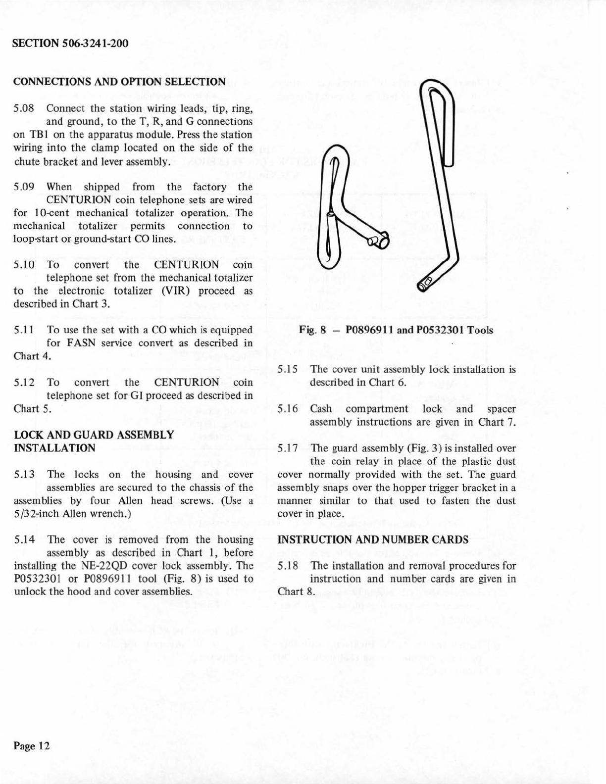
5.14 The cover is removed from
the
housing
assembly
as
described in Chart 1, before
installing the NE-22QD cover lock assembly. The
P0532301 or
P0
89691 l tool (Fig.
8)
is
used
to
unlock the hood and cover assemblies.
Page 12
Fig. 8 -
P0
8969
11
and P0532301 Tools
5.15 The cover unit assembly lock installation is
described in Chart 6.
5.16 Cash compartment lock and spacer
assembly instructions are given in Chart 7.
5.17 The guard assembly (Fig.
3)
is
installed over
the coin relay
in
place
of
the
plastic dust
cover normally provided with the set. The guard
assembly snaps over
th
e hopper trigger bracket in a
manner similar to
that
used
to
fasten
the
dust
cover in place.
INSTRUCTION AND NUMBER CARDS
5.18 The installation and removal procedures for
in
struction and number cards are given in
Chart 8.
SECTION 506-3241-200
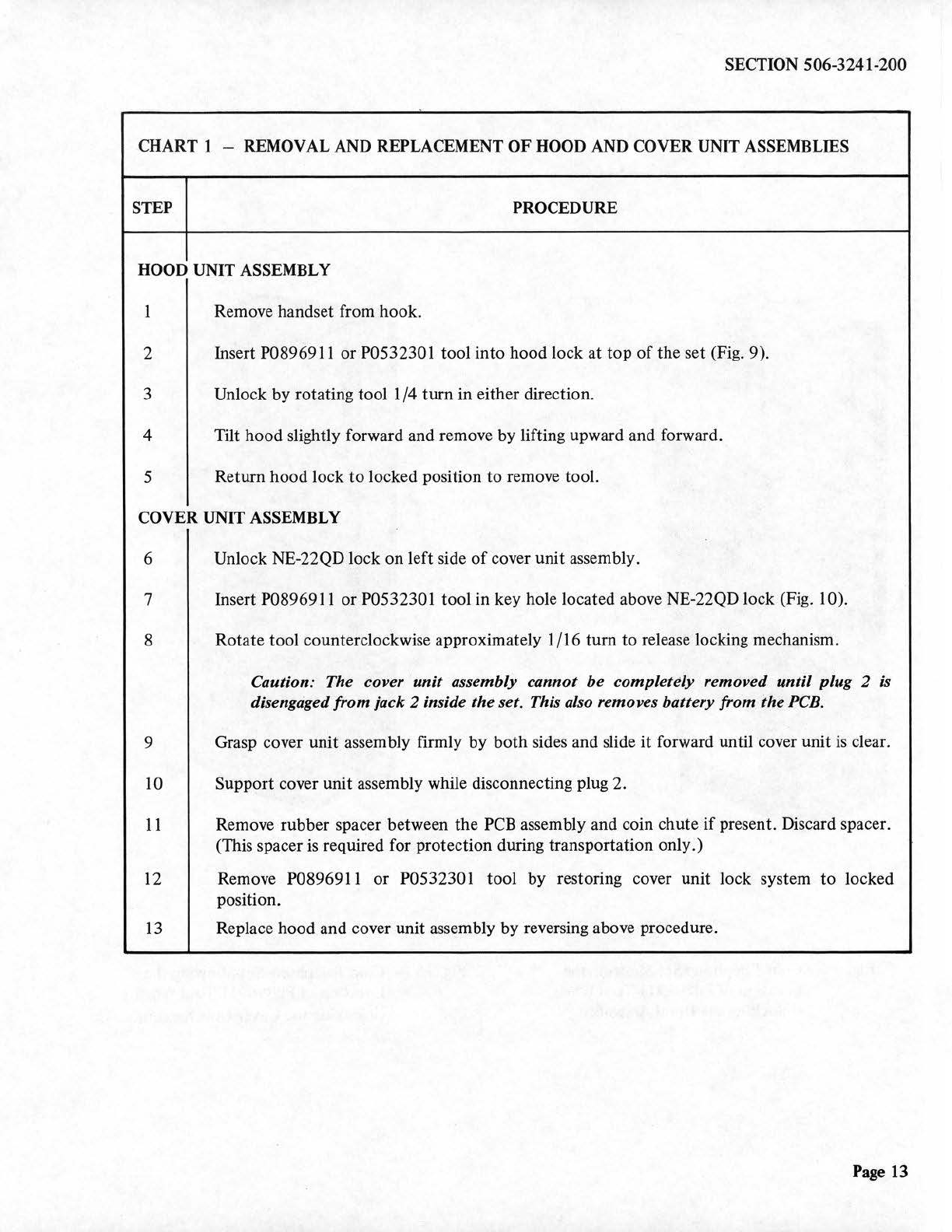
CHART 1 - REMOVAL AND REPLACEMENT
OF
HOOD AND COVER UNIT ASSEMBLIES
STEP PROCEDURE
HOOD UNIT ASSEMBLY
1 Remove handset from hook.
2 Insert P089691 l or P0532301 tool into hood lock at top
of
the set (Fig. 9).
3 Unlock by rotating tool 1/4 turn in either direction.
4 Tilt hood slightly forward and remove by lifting upward and forward.
5 Return hood lock
to
locked position to remove tool.
COVER UNIT ASSEMBLY
6 Unlock NE-22QD lock on left side
of
cover unit assembly.
7 Insert P089691 l or P0532301 tool in key hole located above NE-22QD lock (Fig. 10).
8 Rotate tool counterclockwise approximately 1/16 turn to release locking mechanism.
Caution: The cover unit assembly cannot
be
completely removed until plug 2
is
disengaged from jack 2 inside theset. This also removes battery from the
PCB.
9 Grasp cover unit assembly firmly by both sides and slide
it
forward until cover unit
is
clear.
10 Support cover unit
as
sembly while disconnecting plug 2.
11
Remove rubber spacer between the PCB assembly and coin chute
if
present. Discard spacer.
(This spacer is required for protection during transportation only.)
12
Remove P089691 l
or
P0532301 tool by restoring cover unit lock system to locked
position.
13
Replace hood and cover unit assembly by reversing above procedure.
Page
13
SECT
IO
N 506-3241-
200
INSTRUCTION
CARD
HUMBER
CARD
HOOD
ASSEMBLY
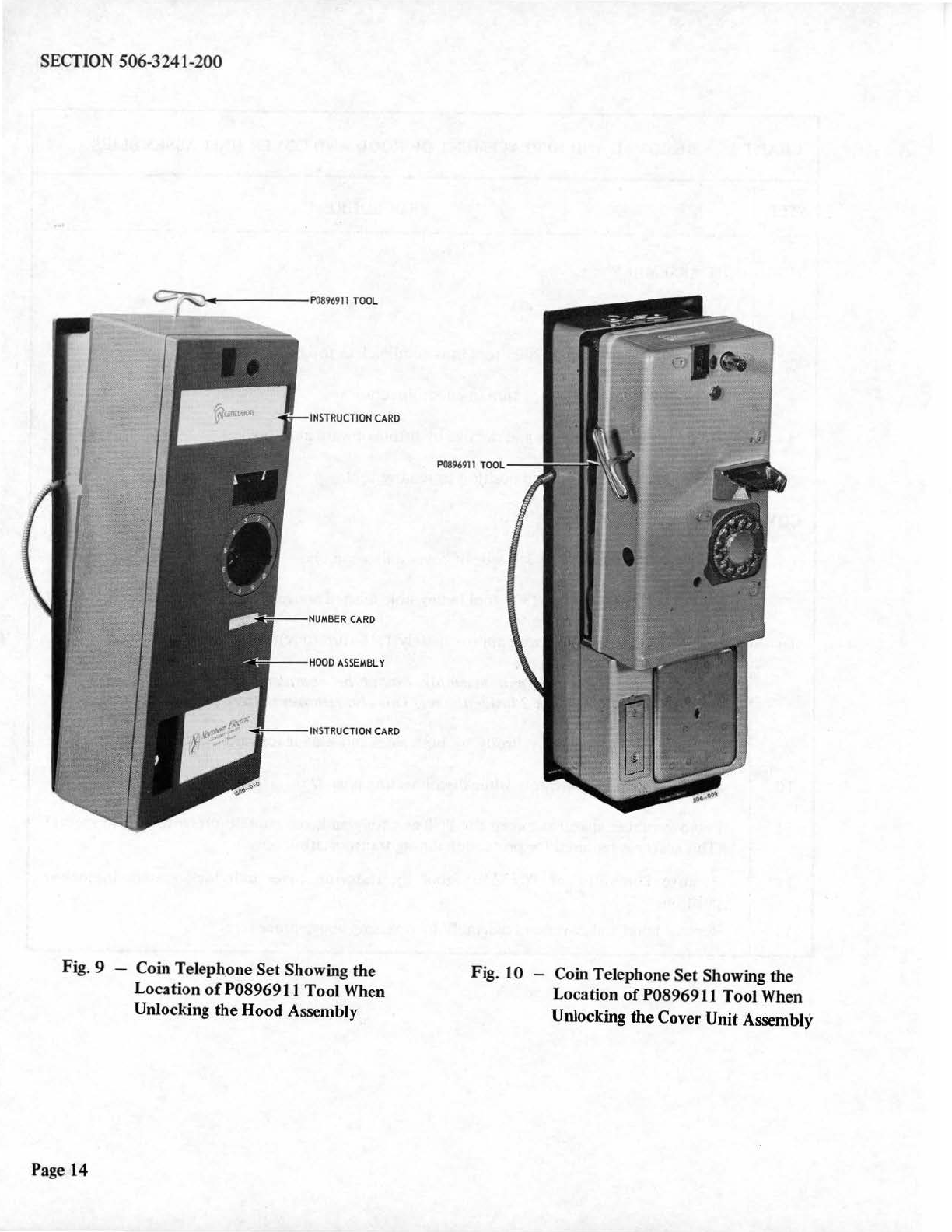
Fig. 9 - Coin Teleph_one Set Showing the
Lo
cation
of
P0896911 Tool When
Unlocking
the
Hood
A~
e
mbly
Page 14
P0896911
TOOL
Fig. 10 -Coin Telephone Set Showing the
Location
of
P0896911 Tool When
Unlocking
the
Cover Unit Assembly
SECTION 506-3241-200
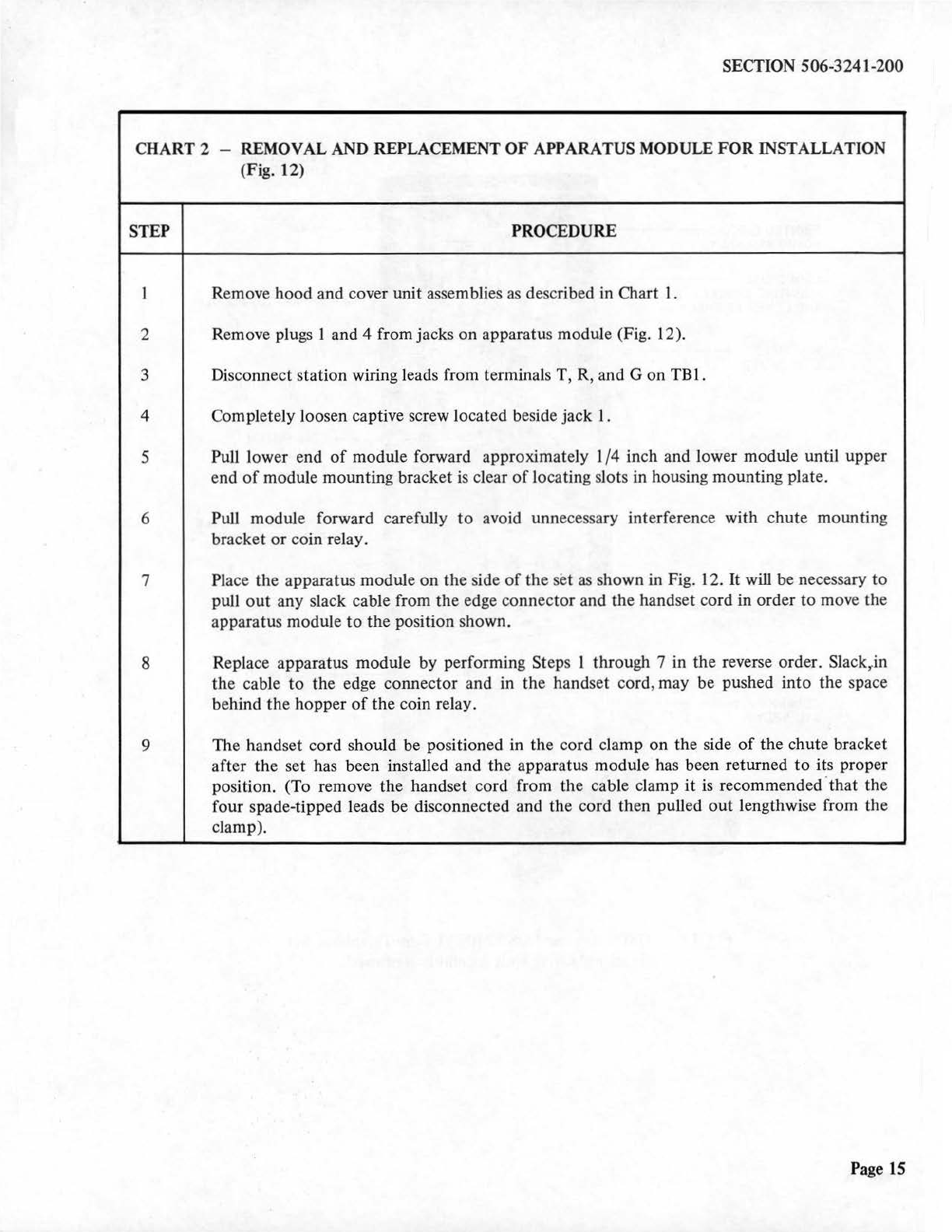
C
HART
2 - REMOVAL AND REPLACEMENT
OF
APPARATUS MODULE
FOR
INSTALLATION
(Fig. 12)
STEP PROCEDURE
1 Remove hood and cover unit assemblies
as
described in Chart 1.
2 Remove pl
ugs
1 and 4 from jacks on apparatus module (Fig. 12).
3 Disconnect station wiring leads from terminals T, R, and G on
TBl.
4 Completely loosen captive screw located beside jack
I.
5 Pull lower e
nd
of
module forward approximately I/4 inch and lower module until upper
end
of
module mounting bracket
is
clear
of
locating slots
in
housing mounting plate.
6 Pull module forward carefully
to
avoid unnecessary interference with chute mounting
bracket
or
coin relay.
7
Pl
ace the apparatus module on the side
of
the set
as
shown in Fig. 12.
It
will be necessary to
pull
out
any slack cable from the edge connector and the handset cord in order to move the
apparatus module
to
the position shown.
8 Replace apparatus module by performing Steps l through 7 in the reverse order. Slack,.in
the cable
to
the edge connector and
in
the handset cord, may be pushed into the space
behind the hopper
of
the coin relay.
9 The handset cord should be positioned
in
the cord clamp on the side
of
the chute bracket
after the set has been installed and the apparatus module has been returned
to
its proper
position. (To remove the handset cord from the cable clamp
it
is recommended·that the
four spade-tipped leads be disconnected and the cord then pulled
out
lengthwise from the
clamp).
Page 15
SECTION 506-3241-200
Page 16
--
-----COIN
RELEASE
LINKAGE
PRINTED
CIRCUIT
PAN
BOARD
ASSEMBLY
COIN
CHUTE
MOUNTING
BRACKET
APPARATUS
MODULE
AND
LEVER
ASSEMBLY
NSQ1016L2
COIN
CHUTE
TBl
STAT
I
ON
WIR
I
NG
CL
AMP
COIN
SWITCH
MODULE
JACK
2
GUARD
ASSEMBLY
APPARATUS
MODULE
RETAINING
SCREW
CHUTE
RETURN
PLUG
1,
JACK
1
ASSEMBLY
PLUG
4,
JACK
4
NE-2A
DOOR
COIN
RETURN
ASSEMBLY
t
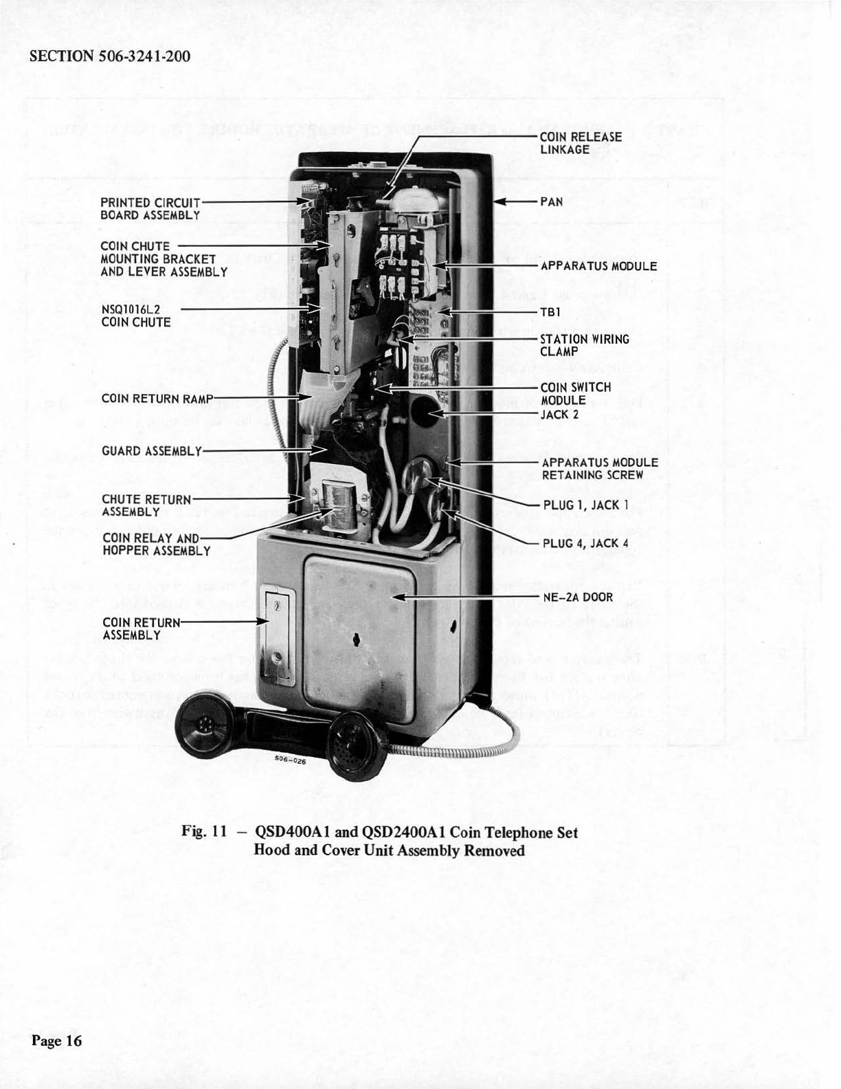
Fig.
11
-QSD400A1 and QSD2400A1 Coin
Te
lephone
Set
Hood
and Cover
Unit
Assembly Removed

PRINTED
C
I
RCUIT--
--~
BOARD
ASSEMBLY
COIN
CHUTE
--
---
--=
MOUNTING
BRACKET
AND
LEVER
ASSEMB
LY
NSQ1016L2
----
------;~
COIN
CHUTE
GUARD
ASSEMBLY
-----=
CHUTE
RETURN---
-___;~
ASSEMBLY
COIN
RELAY
AND
HOPPER
ASSEMBLY
CO
IN
RETURN
---
--11~
ASSEMBLY
SECTION 506-3241-200
COIN
RELEASE
LINKAGE
,.._--
APPARATUS
MODULE
----TBl
~"'"='--=---
-
S
TATION
WIRING
CLAMP
JACK
l
~
t-----
APPARATUS
MODULE
RETAINING
SCREW
~---JACK4
""-----PLUG
l
---
-PLU
G4
'----
-NE-2A
DOOR
Fig. 12 -Apparatus Module Positioned on the Side
of
the Coin
T~lephone
Set for Installation
Page 17

SECTION 506-3241-200
INITIAL
RATE
LEAD
LATCHING
RELAY
TOTALIZER
LEADS
(
CONTROL
LEADS
)
Page 18
INITIAL
RATE
TERMINALS
TERMINALS
FOR
FASN
SERVICE
(BK)
(B
K)
(G)
Fig. 13 -Coin Signaling and VIR
PCB
Assembly
GROUND
ISOLATION
RELAY
LATCHING
RELAY
TOTALIZER
GROUND
ISOLATION
RELAY
LEADS
NOTE
:
WIRING
CONNECTIONS
ARE
SHOWN
FOR
USE
WITH
MECHANICAL
TOTALIZER
AND
GI
NON-OPERATIVE.
INITIAL
RATE
LEAD
IS
SHOWN
STORED
AT
THE
10-CENT
TERMINAL.

SECTION 506-3241-200
CHART 3 - CONVERSION FROM MECHANICAL TO ELECTRONIC TOTALIZER (V
IR
)
STEP . PROCEDURE
1 Ensure
the
CO line is wired for
loop
start. Dial
tone
is
heard
in
handset before any coins are
·deposited.
2 ·· Remove
hood
and cover unit assemblies
as
described in Chart 1.
3 Move S lead
on
TBl
on
apparatus module from terminal 10
to
terminal 4.
4 Remove switch module.
5 Cut
0-W
lead
to
upper
end
of
reed switch
on
coin switch module, insul
ate
and store lead.
6 . Replace switch module.
7 Remove PCB assembly from housing unit assembly.
8 Move R lead
to
required initial
rate
terminal
(Fig~
13
).
9 Move
one
G lead from terminal A
to
terminal
B.
10 Insert PCB assembly.
11
Replace hood and cover unit assembly.
12 Perform
op
era
tion
test described
in
Part 6.
CHART 4 - FASN CONVERSION
STEP PROCEDURE
1 Remove
hood
and cover unit-assembly as described
in
Chart 1.
2 Remove PCB assembly from housing unit assembly.
3 Move G leads from terminals A and B (Fig. 13)
to
FASN terminals C and
D.
Page 19

SECTION
506-3241-200
CHART
4
(Co
nt)
-FASN CONVERSION
STEP
PROCEDURE
4 Insert PCB assembly
in
housing
unit
assembly.
5
At
TBl
on
apparatus
module,
disconnect V-BL
and
Y-BL leads
from
terminals 9
and
6.
Insulate
spade
tips
and
store
leads. (The V-BL lead
may
have
been
removed previously
for
GI.)
6 Replace
hood
and
co
v
er
unit
assembly as described in
Chart
1.
7 Perform
operation
test
described
in
Part
6.
CHART
5 -
GI
CONVERSION
STEP
PROCEDURE
1 Remove
hood
and
cover
unit
assemblies as described
in
Chart
1.
2 Remove PCB assembly
from
housing
unit
assembly.
3 Remove BK
ground
isolation leads (Fig.
13)
from
storage
on
quick-connect
terminal
and
connect
one
lead
to
X and
the
other
lead
to
Y quick-connect terminals.
4 Insert PCB assembly
in
housing
unit
assembly.
5
At
TBI
on
apparatus
module,
disconnect V-BL lead from terminal 9. Insulate
spade
tip
and
store
lead.
(The
V-BL lead
may
have
been
removed previously
for
FASN.)
6 Replace
hood
and
cover
unit
assembly.
7
Perform
operation
test
described
in
Part
6.
Page
20
This manual suits for next models
2


