Northern Industrial Tools PTO-Driven 6" User manual

PTO-Driven 6" Wood Chipper
OWNER’S MANUAL
Read carefully and understand RULES FOR SAFE OPERATION and instructions
before operating. Failure to follow the safety rules and other basic safety precautions
may result in serious personal injury.
Ite m # 1 80 10 0

Thank you very much for choosing a NORTHERN TOOL + EQUIPMENT CO., INC.,
Product! For future reference, please complete the owner’s record below:
Model: _______________ Purchase Date: _______________
Save the receipt, warranty and these instructions. It is important that you read the entire
manual to become familiar with this product before you begin using it.
This machine is designed for certain applications only. Northern Tool + Equipment
strongly recommends this machine is not modified and/or used for any application other
than that for which it was designed. If you have any questions relative to a particular
application, DO NOT use the machine until you have first contacted Northern Tool +
Equipment to determine if it can or should be performed on the product.
For technical questions and replacement parts, please call 1-800-222-5381.
DESCRIPTION & INTENDED USE
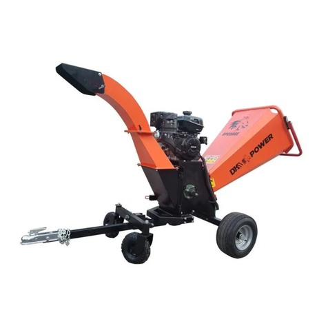
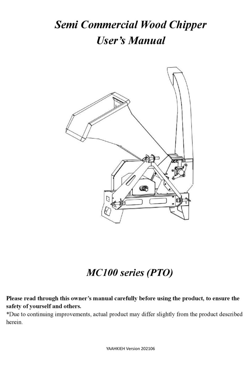
The PTO-DRIVEN 6" wood chipper features an advanced design with a compact structure,
superior technology and substantial attack strength. This model is safe and easy to
operate.
Technical Specifications
Item
Description
PTO
540 RPM
Flywheel Dia.
2 Feet (605mm)
Flywheel RPM
1220
Max Chipping Dia.
6"
Net Weight
772 Lbs. (350 kg)
GENERAL SAFETY RULES
WARNING: Read and understand all instructions. Failure to follow all
instructions listed below may result in electric shock, fire and/or serious injury.
WARNING: The warnings, cautions, and instructions discussed in this
instruction manual cannot cover all possible conditions or situations that could
occur. It must be understood by the operator that common sense and caution are
factors which cannot be built into this product, but must be supplied by the
operator.
SAVE THESE INSTRUCTIONS

WORK AREA
Keep everyone — especially children — away from the area of operation.
Anyone who has not read this manual and received instructions from a
qualified person should not be in the area.
Provided labels on the unit advise the user of proper hitch dimensions and
maximum safe operating speed. Check that proper danger labels are supplied with
the drive-line (replacements are available from your drive-line supplier). Provide
easy-to-understand instructions for proper drive-line operation, maintenance and
repair in the operator’s manual.
PERSONAL SAFETY
Stay alert, watch what you are doing and use common sense when operating a
chipper. Do not use a chipper while you are tired or under the influence of
drugs, alcohol or medication. A moment of inattention while operating a chipper
may result in serious personal injury.
Do not attempt to operate the chipper until you have read and understood the
owner’s manual.
Always keep the guards and chip deflector installed properly while operating
the chipper.
Keep the decals in place and in good repair. The factory or your dealer will furnish
new decals upon request.
Keep hair, hands, feet and other extremities out of and away from the hopper.
Make sure there are no loose ends or strings to be caught by the machine.
Point the discharge chute away from doorways, sidewalks, or any areas where
your view is obstructed. The chute should be pointed downwind when possible or the
fines will blow into your eyes and down your neck.
WEAR PROTECTIVE GEAR:
EYES — Wraparound ANSI-approved safety glasses.
EARS — Ear plugs
HANDS — Leather gloves
FEET — Steel-toed boots
LEGS — Heavy pants
ARMS — Long-sleeved shirt
Always use the appropriate eye and ear protection and other safety equipment.
Safety equipment such as dust mask, non-skid safety shoes and a hardhat used for
appropriate conditions will reduce personal injuries.
Avoid accidental starting. Disconnect chipper from PTO when not in use, and when
moving chipper to another work area.

Never leave the chipper running unattended.
Do not attempt alterations, repairs, or adjustments while the chipper head is
turning. Always disconnect the PTO and stop the motor.
ALWAYS make sure the feed roll drive-shaft and pivots are properly lubricated.
ALWAYS make sure the feed roll clutch is properly lubricated and the clutch
releases when the handle is pushed toward the chute.
ALWAYS make sure the PTO shaft does not come apart or bottom out during
the normal lifting range.
Check the chip pile to see if the blades need to be serviced. Long slivers in the
chip pile are a good indication that the blades are dull and need sharpening.
CAUTION: Turn the chipper head over by hand before applying power to
make sure that the head is clear, all the bolts are clear and the knives clear the
case and cutter bar.
DRIVE-LINE SAFETY CHECKLIST
DRIVE-LINE SPECIFICATIONS The first step toward a safe application is
to specify and test the drive-line to make sure it operates properly
under expected field conditions.
Specify and test the proper size joints and telescoping members based upon the
power required by the implement, speed of rotation, joint angles, shock loads, and
expected life. More information may be found in all drive-line manufacturers’ catalogs.
Design and test the hitch angle to prevent the drive-line from:
Extending beyond the recommended maximum length.
Bottoming out.
Reaching a position that allows joints to lock.
Exceeding the maximum allowable angle for constant velocity (CV) joints.
Specify and test telescoping members to allow the lowest possible thrust loads,
considering the expected working conditions.
Specify and test torque limiters to control excessive shock loads. Where necessary,
specify and test overrunning clutches to prevent inertial loads from overpowering the
tractor.
Specify and test torque limiters to control excessive shock loads.
Where necessary, specify and test overrunning clutches to prevent inertial loads from
overpowering the tractor.
HAZARD REDUCTION The second step in specifying a safe drive-line
application is to eliminate as many hazards as possible.

On drive-lines with torque limiting or overrunning devices, specify that the device be
positioned on the end of the drive-line by the implement.
For implement connections which require bolts or set screws, select and/or supply
hardware which minimizes protrusions.
For tractor PTO shaft connections, specify a safety type yoke (twist or slide collar) to
minimize protrusions.
Provide a proper clearance zone for the operation of the drive-line to avoid damaging
the shielding components.
Some common areas of interference are:
Three point linkage.
Extended or eye loop hitch pins.
Hydraulic hoses.
GUARDING Hazards which cannot be eliminated effectively must be
guarded against at all times.
The PTO master shield, integral drive-line shield and implement input connection
shield should provide an interactive guarding system.
Provide instructions by labels or manuals. The implement should be used only with
the tractor’s PTO master shield in place.
Specify and test an integral drive-line shield with end cones which will overlap, but not
interfere with the PTO master shield or implement input connection shield.
Provide an implement input connection shield to interact with the integral drive-line
shield to provide guarding of the shaft coupling and any torque limiting device installed
on the drive-line.
Check that all routine maintenance of the drive-line can be done without removal of
the shields.
MACHINE OPERATION
CAUTION! Turn the chipper head over by hand before applying power to make
sure that the head is clear, all the bolts are clear and the knives clear the case and cutter
bar.
CAUTION: Do not move the unit while the flywheel is turning. Block the wheels and
set the brake while running the head.
This manual suits for next models
1
Table of contents
Other Northern Industrial Tools Chipper manuals

