Northern Lights ARC-102 User manual
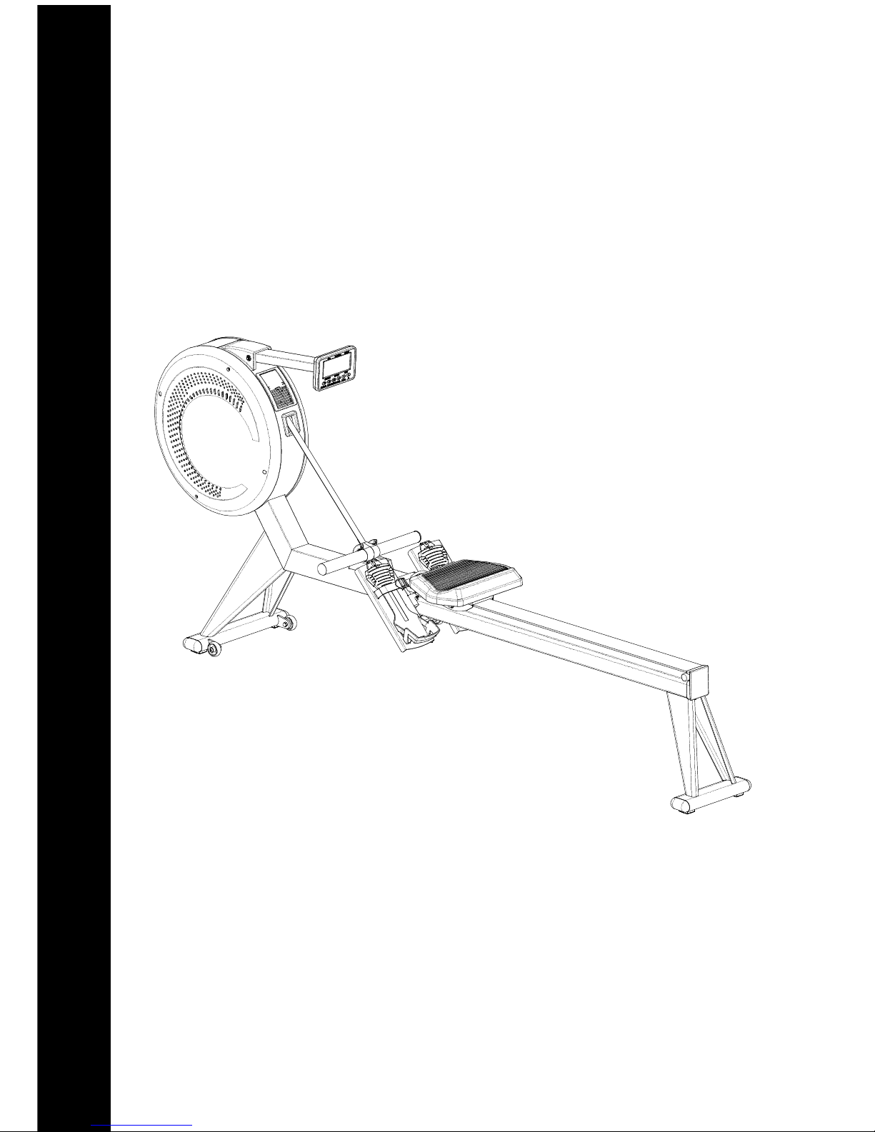
ARC-102
Assembly Guide and Owner's Manual
SAVE THE INSTRUCTION - THINK SAFETY!
Air Rower
Revision-1114

IMPORTANT
Read all assembly instructions and safety precautions; reference all safety guidelines and
warning labels before using this product. Please sa e the instructions afterward for future
reference as the instructions are written for your safety and to protect the unit.
SAFETY
Properly warm up and stretch before exercising. If you feel pain or dizziness at any time
while exercising, stop immediately and consult your physician.
Obtaining Service
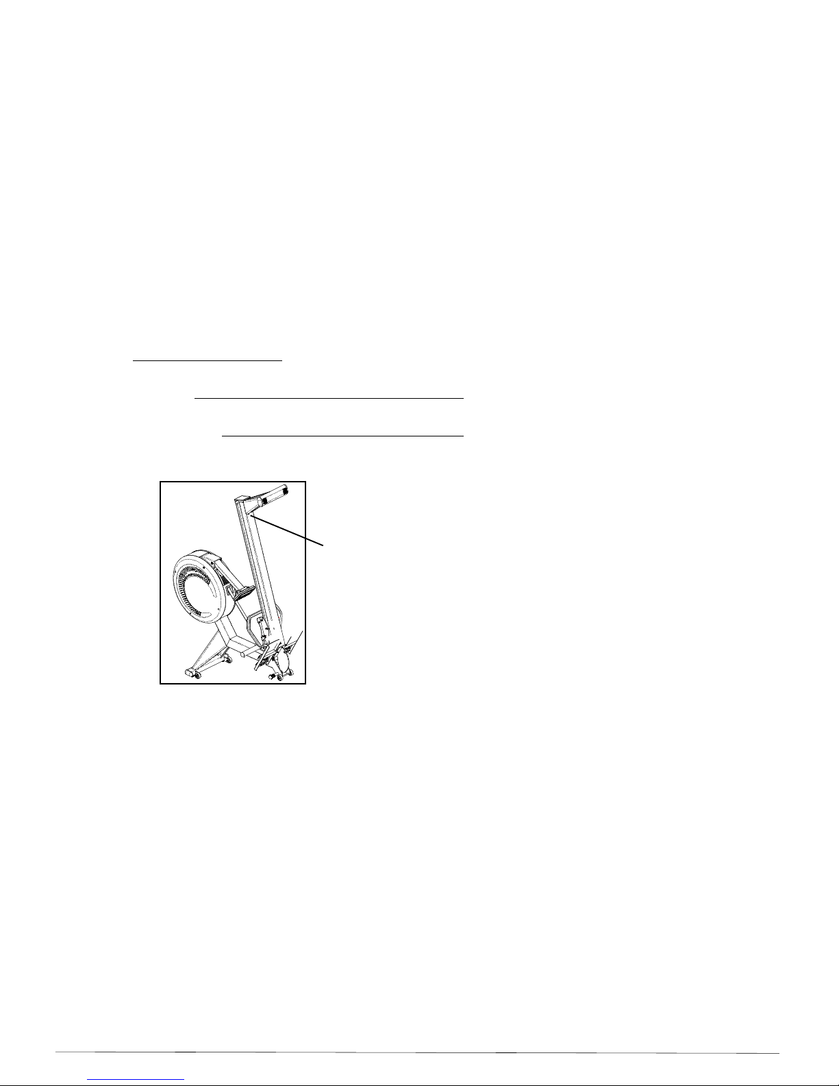
Before proceeding, find the Air Rower's model, serial number located on the Rear Stabilizer
and enter it in the space pro ided below.
Model:
Serial Number:
Date of Purchased: month / date / year
» Refer to the SERIAL NUMBER and MODEL NAME when calling for ser ice.
SAVE THE INSTRUCTION - THINK SAFETY!
Assembly Guide and Owner’s Manual Page 1
Serial Number is located
on the back of the Rail

Important Safety Instructions & Warnings
WARNIN
To reduce the risk of burns, fire of burns, fire, electric shock, or injury to persons,
read the following precautions before assembling or using your new product.
Read all instructions and enclosed literature carefully. Understand the assembly and
operation before using the equipment.
The Air Rower should ne er be left unattended when plugged in. Disconnect the Air Rower by
unplugging the adaptor from outlet when the unit is not in use, and perform maintenance.
Close super ision is necessary when this Air Rower is used by or near children.
Do not allow children or people unfamiliar with the operation of this equipment, on or near it.
Keep hands and feet from all mo ing parts, which could result in serious injury.
Ne er operate this unit if it has a damaged cord or adaptor, if it is not working properly,
Contact your authorized dealer for ser ice.
Keep the cord away from heated surfaces.
Do not operate where aerosol (spray) products are being used or where oxygen is being
administered.
Keep equipment away from water and moisture. A oid dropping anything on or spilling
anything inside the equipment to pre ent electric shock or damage to the electronics. Do not
operate electrically powered equipment in damp or wet locations.
Ne er drop or insert any object into any opening.
Do not use outdoors.
Do not attempt to use the Air Rower for any purpose other than for the purpose it is intended.
Route the Adaptor Cord so that it is not walked on, pinched, or damaged by the parts placed upon,
Assembly Guide and Owner’s Manual
Page 2
including the equipment itself.
It is necessary to inspect this unit periodically to maintain safety and proper function.
Always wear proper clothing and shoes when exercising to avoid getting caught in the moving parts.
Always stretch and warm up before starting any exercise program.
Make sure all components are fastened securely at all times.

Table of Contents
Important Safety, Obtaining Service……………………………………………….........................
Important Safety Instructions & Warning………………………………………………………........
Table of Contents………………………………………………………………………………………
Parts for Assembly…………………………………………………………………….......................
Assembly Instructions………………………………………………………………………………….
Console Operation Instructions…………………………………………………………………….....
User's Manual ………………………………………………………………………...........................
Parts Diagram……………………………………………………………………................................
Parts List…………………………………………………………………………….............................
1
2
3
4
5-8
9-13
14-16
17
18-19
Assembly Guide and Owner’s Manual Page 3
8
MM
6
MM
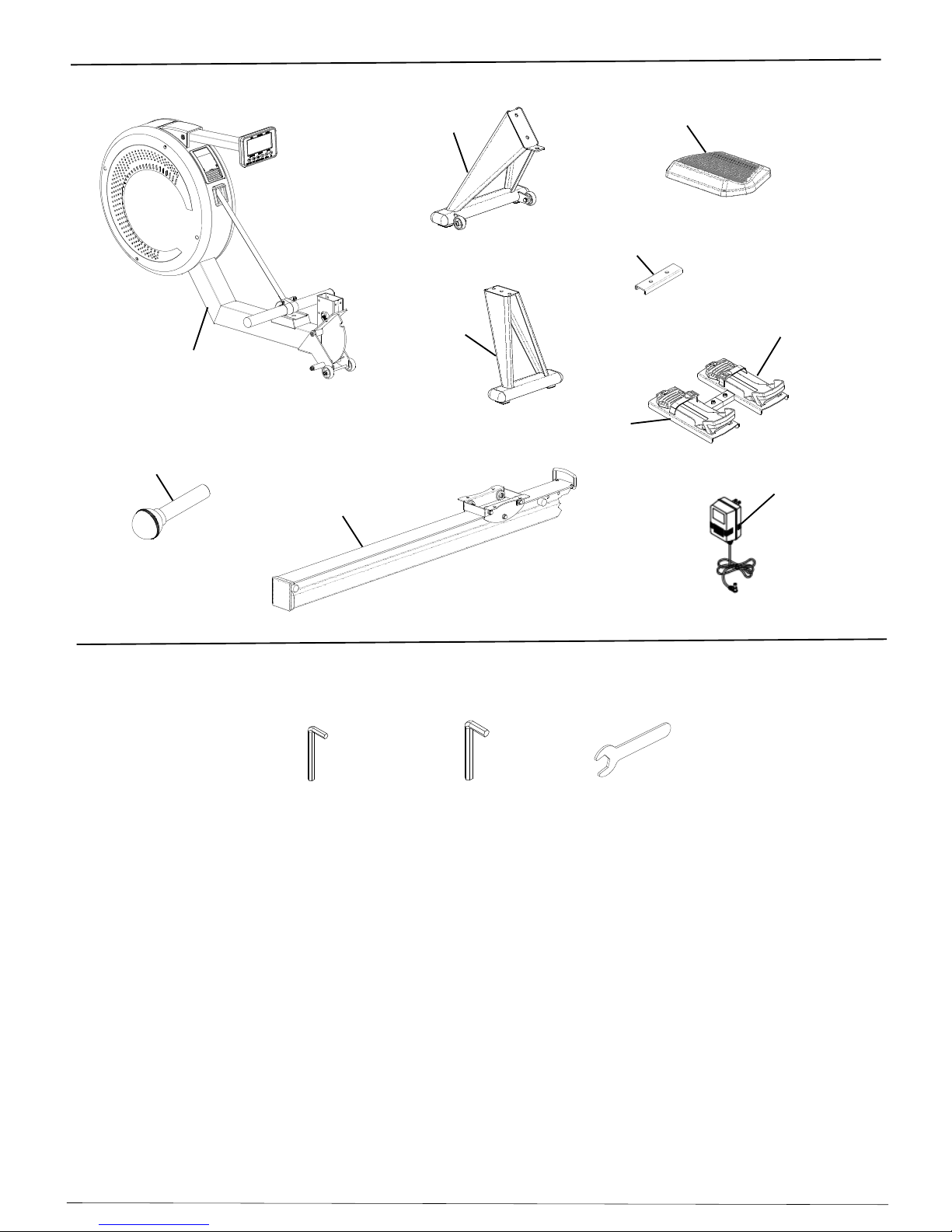
Tools Required:
Allen Wrench Allen Wrench
A1
D1
C1
B1
Parts for Assembly
B3
E1L
E1R
Assembly Guide and Owner’s Manual
Page 4
A5
M14
Wrench
A27
E10
Assembly Instructions
have
no
damage.
function, and safetyforthe
Multi Jungle System
workout.
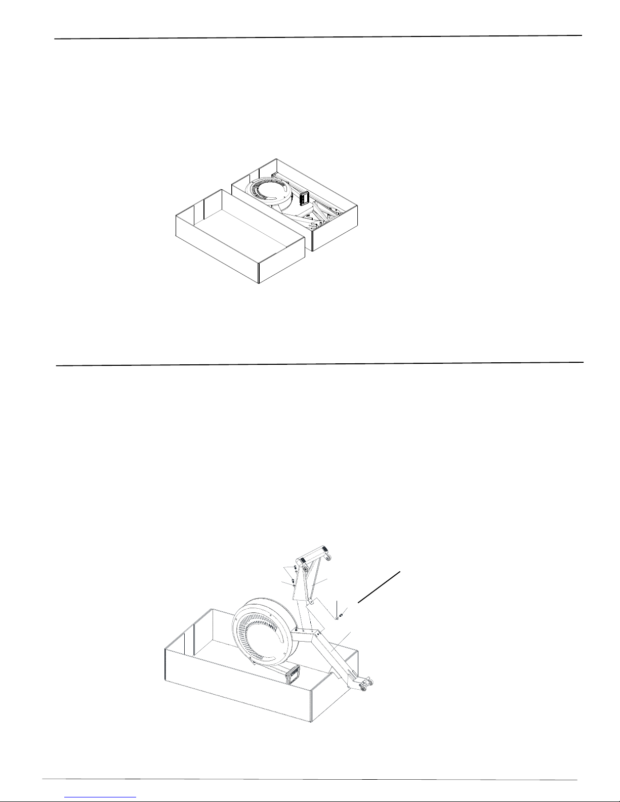
*Separate all of the parts after opening the box and verify that all parts are accounted for and
*Assemble the machine on a solid level surface. This will ensure the best possible performance,
*Clear a big enough working space before unpacking the box.
*Double check the packing materials to ensure no parts were accidentally thrown away.
Caution: Additional assitance is needed to help turn main frame assembly.
Step 2
With additional assistance carefully turn the Main Frame Assembly (A1) upside down, fitting in
Remove the preassembled 2- M10x16mm Cap Head Socket Screws (C4) and 2- M10 Flat
flat washers to secure the front stabilizer.
Assembly Guide and Owner’s Manual Page 5
the styrofoam in the carton as shown below.
Step 1
*Before assembling the Air Rower, distinguish a proper and appropriate location for the unit.
Important: Make sure the Main Frame Assembly is stabilized before the next assembly.
Washers (C7) from the the Main Frame Assembly (A1) with 8mm Allen wrench.
Assemble the Front Stabilizer (C1) to the Main Frame Assembly using the same 2 screws and
This Screw needs to
be securely tightened first.
Note:
C7
C7
A1
C4
C1
C4

Assembly Instructions
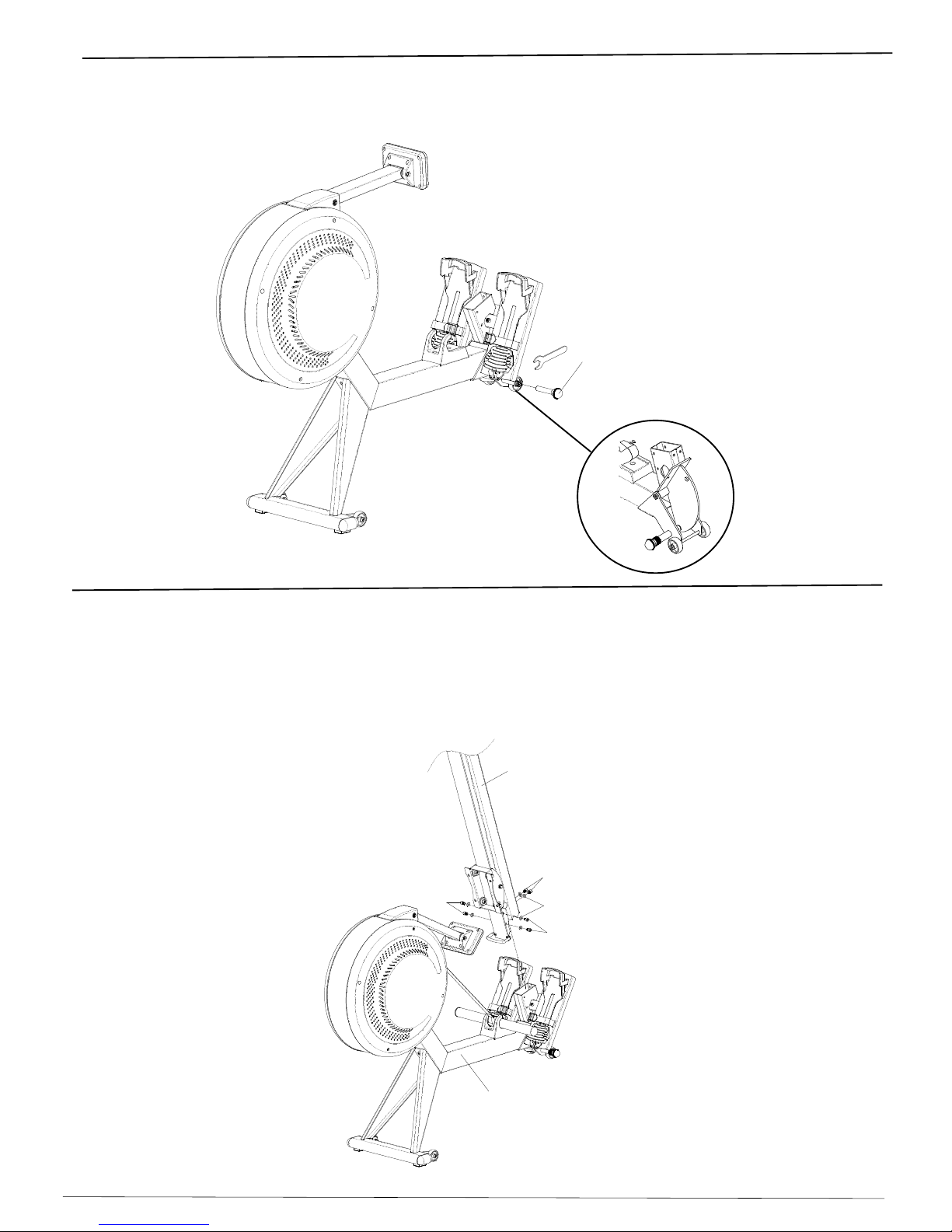
Step 3
With additional assistance, carefully turn the Air Rower around to the upright position as shown below.
Remove the preassembled 6- M8 x 16mm Cap Head Screws (B4) and 2- M8 x 25mm Cap Head
Screws (E8) and 6- M8x16 Flat Washers (B12) from the Main Frame Assembly with the 6mm
the Foot Rests to the Main Frame Assembly. See Figure B
Assembly Guide and Owner’s Manual
Page 6
Step 4
Remove 2- M10 x 16mm Cap Head Screws (C4) and 2- M10 Flat Washers (C7) from
Place the Rail (B1) across the carton as shown below, make sure the Seat Carriage beyond
the carton edge.
Attach the Rear Stabilizer (D1) to the Rail using the same 2 screws and flat washers to secure
Foot Rests (E1L & E1R) through the Main Frame Assembly and insert the Left Foot Rest into
the Right Foot Rest, then use the same 2- M8x25mm Cap Head screws to secure the Foot Rests
C7
D1 B1
C4
the Rail (B1) with 8mm Allen wrench.
the Rear Stabilizer.
B12
B4
B4
B4
E8
B12
Allen Wrench. See Figure A.
E8
E1R
A1
E1L
E8
E10
Figure A Figure B
Insert the Foot Bed Mounting Plate (E10) onto Left Foot Rest (E1L), then place the Left and Right
Assembly Instructions
Step 5
A5
Step 6
Gently slide the Rail (B1) into the Main Frame Assembly (A1), then use the same 6 screws and
flat washers to secure the Rail to the Main Frame Assembly.
Assembly Guide and Owner’s Manual Page 7
With the supplied M14 Wrench, tighten the Pull Pin (A5) into the Main Frame Assembly
Remove the preassembled 6- M8x16mm Cap Head Screws (B4) and 6- M8 Flat Washers (B12)
from the Main Frame Assembly with 6mm Allen Wrench.
as shown below.
B4
B4
A1
B4
B1
B12

Assembly Instructions
Step 7
Assembly Guide and Owner’s Manual Page 8
Attach the Seat (B3) to the Seat Carriage as shown,make sure the pointed portion of the seat
Remove the preassembled 4- M8x16mm Cap Head Screws (B4) and 4- M8 Flat Washers (B12)
from the Seat Carriage with the 6mm Allen wrench.
faces downward. Use the same 4 screws and flat washers to secure the Seat.
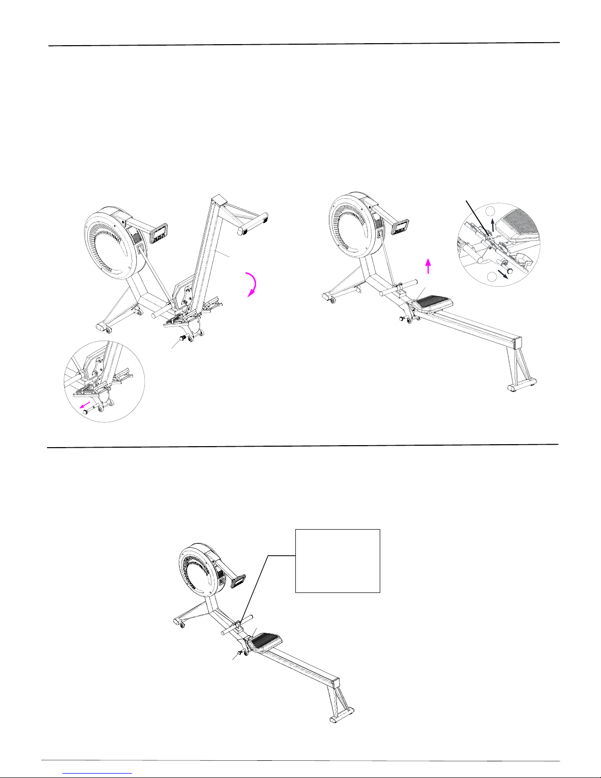
Step 8
One hand holds the Rail (B1) and the other hand pulls out the Pull Pin (A5), then release the pin,
carefully put down the rail to the floor.
Lift up the rail handle until hear a "clicking" sound, make sure the pin is locked in
the hole of Pviot Assembly.
在
Assembly for the ARC-102 Air Rower is complete.
The Computer Arm (F1) or the Computer (F2) can be adjusted to the desired position.
F2
F1
As shown above,
B4
B3
B1
B12
After completing the Step 7 assembly,
Mind your head not to hit the rear stabilizer
Caution:
while gettting up.
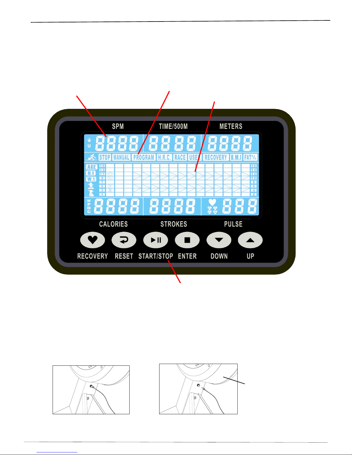
Function Keys
Console Operation Instructions
Matrix Profile Window
Program Selection Window
Data Display Window
OPERATION】
1.Poweron
Please read the console operation instruction thoroughly and familiarize yourself with
the console layout before choosing a workout.
Console Layout
Insert the power adaptor jacket into the power socket under the Mesh (G4) of the main frame
as shown below, then plug the power adaptor into the wall outlet.
Important: Use only the power adaptor accompanying with the machine. Never use an adaptor
that is not certified for the unit, it will cause malfunction.
Assembly Guide and Owner’s Manual Page 9
G4
Make sure the Rower is powered up before you start using the console.
This unit is powered by AC Adaptor.

Console Operation Instructions
Assembly Guide and Owner’s Manual Page 10
2. How to Adjust Time and Date
Year Month Day
Hour Minute
When the power is connected, the computer will turn on automatically, and starts segment tests with a beep,
then it enters the Time and Date Adjustment as shown below.
When the Adaptor or the Adaptor jacket is plugged off and re-plugged in,
the time and date need re-inputting.
When the Time and Date are not adjusted in 30 seconds, it enters Sleep Mode.
Press any key to enter the program selections.
Note: The "Time and Date" wording on the console only indicates where to adjust the Time and Date,
The Hour or Minute is blinking for inputting the current time.
Use Up or Down Key to adjust the current hour and minute, after each number is input then press enter
2-1. Adjust the Time.
2-2. Adjust the Date
The sequential input is hour, minute, and then year, month and day.
for the next input.
The Year or Month or Day is blinking for inputting the current date.
Use Up or Down Key to adjust the current year, Month, and Day, after each number is input then press enter
for the next input.
it is not embedded in.
STOP/MANUAL/PROGRAM/H.R.C./RACE/USER
PressUP or DOWNforfunction selection and ENTERforconfirmation.
3. Program Selection
After the Time and Date are adjusted, it enters the program selections:
blinking tobeselected, Key

2.
2. FUNCTIONS
TIME Preset targettimebypressing UPand DOWNbuttons(1min~99 min),eachincrease/
decreasesetting is1minute.
TIME/500M Computerwilldisplaythetimeneeded torow500 metersaccordingtocurrent speed.
DISTANCE Preset target value bypressing UPand DOWNbuttons(10meters~9990meters), each
increase/ decreasesetting is100 meters.
STROKES Preset targetvalue bypressing UPand DOWNbuttons(0~9999 strokes). eachincrease/
decreasesetting is10.
TOTALSTROKES Accumulatestotalstrokesfrom0up to9999.
PULSE Topreset targetvalue bypressing up/down/mode from30to240,eachincrease/decrease
setting is1.The monitorwilldisplayuser sheartrateduring training.The pulsemeasurement
functionisonlyused bychest belt system;the frequencyofchest belt accepted bythe
monitoris5KHz.
RECOVERY Afterexercising foraperiod oftime, keep holding on handgripsand press “RECOVERY”
button. Allfunction displaywillstop except “TIME”startscounting downfrom00:60 to00:00.
Screen willdisplayyourheartraterecoverystatuswiththe F1,F2….toF6.F1isthe best, F6
istheworst. Usermaykeep exercisingtoimprovetheheart raterecoverystatus.(Press the
RECOVERYbutton againtoreturnthe maindisplay.)
CALENDAR The monitorwilldisplayyear,month, and daywhen monitorisinsleep mode.
TEMPERATURE The monitorwilldisplaycurrentroomtemperaturefrom0to60when the monitorisin
sleep mode.
CLOCK The monitorwilldisplaycurrentclock when the monitorisinsleep mode.
Console Operation Instructions
1. Keys:Thereare6 function keysforprogramoperation.
UP or DOWN To press these two buttons through available selection.
To adjust thefunction valueupwardanddownward.
ENTER Toconfirmyourselection or data entry.
During training,press the button toscan eachdisplayfunction.
START /STOP Tostart and stop yourselected workout program.
RESET Toreset the computerbacktothe main menu.
RECOVERY ToactivatetheRECOVERYPROGRAM thatwillautomaticallyevaluateyourfitness immediately
afteryourwork out.
Assembly Guide and Owner’s Manual Page 11

Assembly Guide and Owner’s Manual
Page 12
3-1. MANUAL PROGRAM
A.Enterintothisfunction, “L1”will display on the matrix profile window forresistancesetting,
you can set the target resistancefromL1 toL16 bypressing UP orDOWN and then ENTER
button.
Afterpressing the ENTER, you canset target value forTIME,DISTANCE, STROKES,
CALORIES, PULSE.
Note:AsTimeisset, the DISTANCEcan t be set, if youset the targettimeyou wishtoexercise, each
segment wouldcontainthe timelengthof targetvalue dividedby16.
AsDISTANCEhasbeen set, the TIME can tbe set, if you set the target distanceyou wishto
exercise, eachsegment wouldcontainthe distancelengthoftarget valuedivided by16.
Ifyoudidn t setthe valueofTIMEorDISTANCE,eachsegment wouldcontainthe distance
lengthof 100M.
B.Press START button tostartexercise,the STOPsign willdisappear.Allvaluesstartcounting up ordown.
Press UPorDOWNbutton toadjust the resistanceasyou want and itsfigurewill displayon the matrix
(level 1~level16).
C.Whenthe anytarget value ofyou set count downtozerooryou havepressed the STOPbutton,the
monitorwillstop and displaythe average figureofTIME/500M.
Each Data Display window will blink to input the data.
Console Operation Instructions
3-2. PROGRAM
Usercan select12 different programprofiles bypressing Afterselected,
usercanset the exerciselevel fromL1 toL16 bypressing
Also
can
adjust thelevel during exercising.
A.Enterintothisfunction,press UP/DOWNtoselect the target profile, and press ENTERfor
confirmation.Then “L1”willdisplayon the monitor,you can pressUP/DOWN/ENTERbuttontoset target
exerciselevelfromL1 toL16.Afterlevelconfirmed,
Note:AsTimeisset, the DISTANCEcan t be set, if youset the targettimeyou wishtoexercise, each
segment wouldcontainthe timelengthof targetvalue dividedby16.
AsDISTANCEhasbeen set, the TIME can tbe set, if you set the target distanceyou wishto
exercise, eachsegment wouldcontainthe distancelengthoftarget valuedivided by16.
If you didn t setthe valueofTIMEorDISTANCE,eachsegment wouldcontainthedistancelength
of 100M.
B. Press STARTbutton tostart exercise,the STOPsignwilldisappear.All valuesstart counting up ordown.
Press UPorDOWNbutton toadjust the resistanceasyou want and itsfigurewill displayon the matrix
(level 1~level16).During exercising,the value ofTIMEand TIME/500Mwillbe scanned in6seconds
automatically.
C.When the anytarget value of you set countdowntozerooryou havepressed the STOPbutton,the
monitorwillstop and displaythe average figureofTIME/500Mand SPM.
UP or DOWN and then ENTERbutton.
UP or DOWN and then ENTERbutton.
you canset target value forTIME,DISTANCE, STROKES,
CALORIES, PULSE.
Each Data Display window will blink to input the data.
3. PROGRAMS
PROGRAMPROGRAM
P1 Peak P7 Canyon
P2 LongitudinalValleyP8 Hillvalley
P3 Valley P9 Hills
P4 Hill P10 Mountain
P5 Hillcliff P11 Highland valley
P6 Highland P12 Highland longitudinalvalley
CODE CODE

3-3. H.R.C.
You can preset the target percentage forheartratecontrolinthisfunction.
A.Enterintothisfunction,the monitorwillblink “AGE25”,press UP or DOWN and then ENTER button to
set your age., Afterconfirmed, youcan selectthe percentage of heart rate55%, 75%,90%, and TAG
Assembly Guide and Owner’s Manual Page 13
blinking inpulse display window. If the percentage ofheartratedoesn tmeet yourdemand,
youcan alsoset yourdesired heartrate value bypressing
afterTAGselected.
Aftertargetheart rateconfirmed,
UP orDOWN and then ENTERbutton.
you canset target value forTIME,DISTANCE, STROKES,
CALORIES, PULSE.
Each Data Display window will blink to input the data.
Note:AsTimeisset, the DISTANCEcan t be set, if youset the targettimeyou wishtoexercise, each
segment wouldcontainthe timelengthof target valuedividedby16.AsDISTANCEhasbeen set,
the TIME can tbe set, if you set the targetdistanceyou wishtoexercise, eachsegmentwould
containthe distancelengthof targetvalue divided by16. If you didn t set the value ofTIMEor
DISTANCE, eachsegment wouldcontainthe distancelengthof 100M.
B.Press START button tostartexercise,the STOPsign willdisappear.Allvaluesstartcounting up ordown.
During exercising, thevalue ofTIMEand TIME/500M, STROKES and TOTALSTROKES, CALORIES
willbe switched ineach6secondsautomatically.You mayalsopress “ENTER”toshowTIME,SPM,
DISTANCE,STROKES, and CALORIESineach data display window.
Console Operation Instructions
C.When the anytargetvalue ofyou setcountdowntozero(the computerwillremind you withbeep sound)
oryou havepressed the STOPbutton, the computer will stop and displayyourcurrent heart rate.
Note:Thecomputerwillkeep following yourheart ratevalue and adjust the resistanceautomatically
during exercising,when yourheart rateislowerthan targetvalue,the resistancewillbe
increased one levelup(L1, L2,L3…)bycomputerineach30 secondsautomaticallytillL16.
Whenyourheartratereached targetvalue,the resistancewillbe decreased one leveldown
immediately,if yourheart ratekeep overtarget value, the resistancewillbe decreased one level
down (L16, L15, L14,..)bycomputerautomaticallyineach15 seconds.
Whenyourheartrateisovertarget value and resistancehasdowned tolowest (L1)oryourheart
ratekeep lowerthan targetvalue and resistancehasreached highest (L16), the computerwill
remind you withbeep sound.
Whenyourheartratekeep higherthan target value over30 secondsat lowest resistance(L1),
theycomputerwillSTOPautomatically,itsprotection systemforheartratecontrol.

3-4. RACE
A.Enterintothe RACE,the TIME/500Mdisplays8:00.You can press UPorDOWN and then ENTER button
toset difficulty level of L1 ~L15 whichyou want toracewithmonitorimmediately,then press ENTERto
confirm.Then you can set the targetracedistancebypressing
The difficulty level of L1 ~L15 figureof the TIME/500Misasfollows:
L1 =8:00; L2 =7:30 ;L3 =7:00 ; L4 =6:30 ;L5 =6:00
L6 =5:30; L7 =5:00 ;L8 =4:30 ; L9 =4:00 ;L10 =3:30
L11=3:00 ; L12 =2:30 ;L13 =2:00 ;L14 =1:30 ;L15 =1:00
B.Press STARTbutton tostart raceand STOPsign willdisappear.The U&PBwilldisplayinthe matrix.
The monitorwillSTOPwhen one hasreached the distanceofracewhichhasbeen set before,then the
matrixdisplays “PCWIN”or “USERWIN”and maydisplayfigureforthe statusofthe SPMvalue during
allexerciseafter6seconds.
C.Whenthe raceisover, you can press the STARTtohavearaceonceagain, press reset toleavethe
stateofthe race.
Assembly Guide and Owner’s Manual
Page 14
Console Operation Instructions
Enterintothisfunction, you mayset thedesired programprofilefortraining, press
toset up exercising graph you wish.
A.Afterconfirmeduserfunction,you can see the firstcolumnblinkon the monitor, and press
UP/DOWN/ ENTERtoset thelevelfrom1to16,the eachgridincrease/decreaseis2levels. Holdthe
ENTERfor2secondstoenterintoinitial(standby) mode, then you canset targetvalue forTIME,
DISTANCE,STROKES, CALORIES, PULSEforsetting.
B. Press START button to start exercise, the STOP sign will disapper. All values start counting up or down.
TIME/500M,STROKESand TOTALSTROKES and CALORIESwillbe switched ineach6seconds
automatically. You mayalsopress “ENTER”toshowTIME,SPM, DISTANCE, STROKES, and
CALORIESin each Data Display window.
C. Press STOP Button to stop the exercise, the computer will stop and display your current heart rate on the
3-5. USER
matrix profile window and TIME and TIME/500M will blink in turn every 6 seconds.
You can press UP or DOWN button to adjust the resistance for each blinking program profile as your
wish (all profiles will blink in sequence automatically). During exercising, the values of TIME
UPorDOWN and then ENTER button
UPorDOWN and then
ENTER button
Assembly Guide and Owner’s Manual Page 15
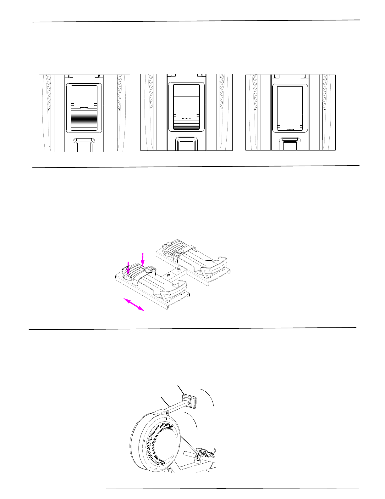
User's Manual
Air Vent Adjustment
The Air Rower's flywheel fan generates an air flow that can be directed with sliding the flip
upward to open the vent or shut it down, as shown below.
Heel Support Adjustment
Press down 2 buttons in the foot rest tread with 2 fingers at the same time as shown below.
and slide the heel support to the desired fitting position.
When the foot is properly positioned, pull on the strap to tighten foot securely to foot pedals.
F2
F1
Computer Angle Adjustment
The Computer and computer arm can be adjusted to accommodate to the users height
and desired view.
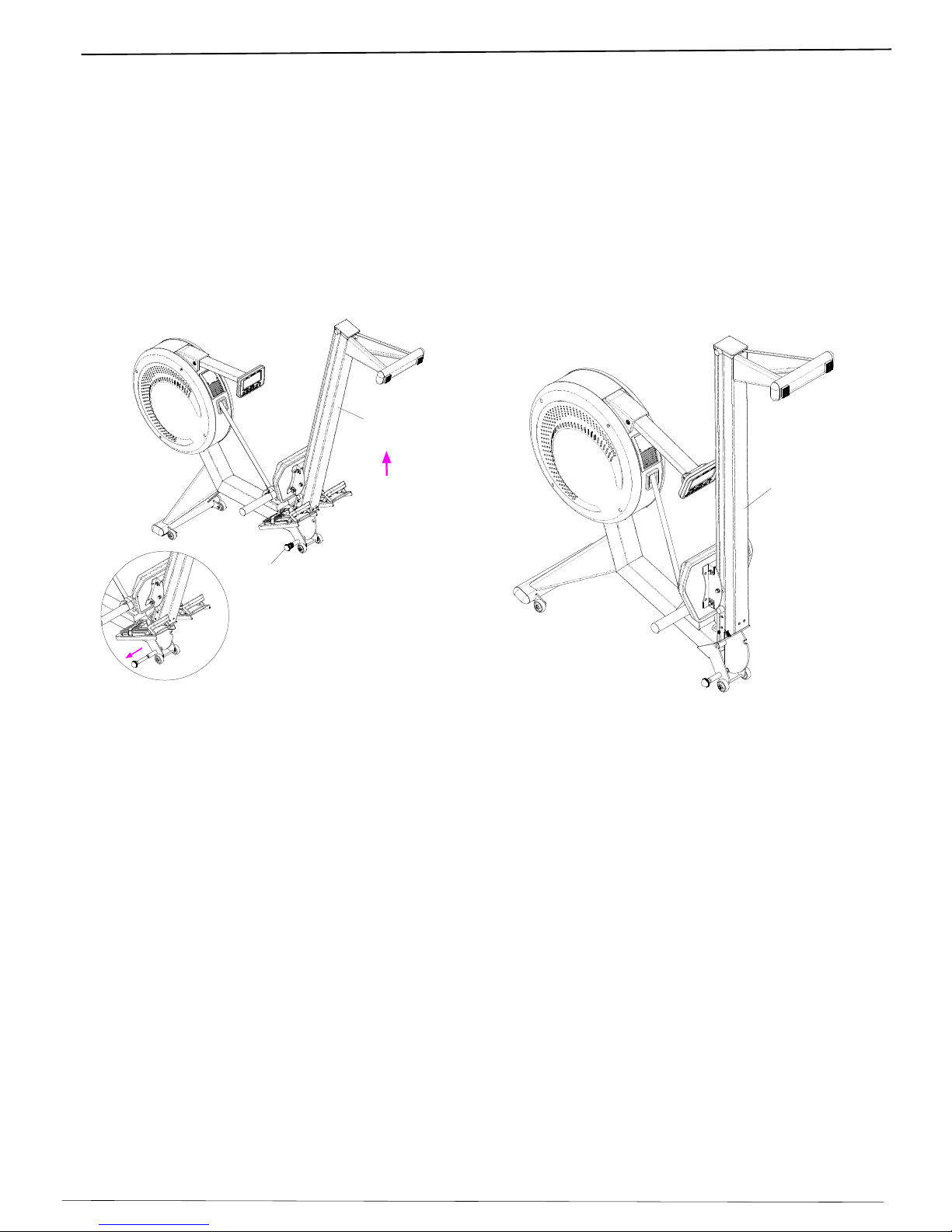
User's Manual
Folding the Air Rower
Important: For Safety, while Folding or Unfolding the Air Rower, make sure there are no other persons,
children, pets around the machine.
A5
B1
Pull out the Pull Pin (A5) and carefully lift up the Rail (B1) to the upright position,
B1
until hear a "clicking" sound. Make sure the pull pin is locked before moving the Air Rower.
Transportation and Storage
Before transporting the Air Rower, make sure the Rail (B1) is in the folded position.
Slowly move the Rower with both hands to the desired storage or new work-out location.
Assembly Guide and Owner’s Manual
Page 16
User's Manual
Un-folding the Air Rower
Important: For Safety, while Folding or Unfolding the Air Rower, make sure there are no other persons,
children, pets around the machine.
One Hand Holds the Rail (B1), and the other hand pulls out the Pull Pin (A5).
Release the Pull Pin, slowly and carefully place the Rail with both hands down to the floor.
Grab and Lift up the Lift Handle (B10) located at the front Rail until hear a " clicking" sound.
Assembly Guide and Owner’s Manual Page 17
A5
B1
B12
A5
Heart Rate
Receiverbuilt-in
inside the Plastic
HandleBar
Holder
The Air Rower is equipped with a built-in wireless receiver for the heart rate monitoring transmitter.
Make sure the pull pin is locked before exercise.
B10
Heart Rate Monitoring Device
Please contact the authorized delear to purchase a compatible chest strap transmitter if
you want to use wireless heart rate features.
1
2
B10
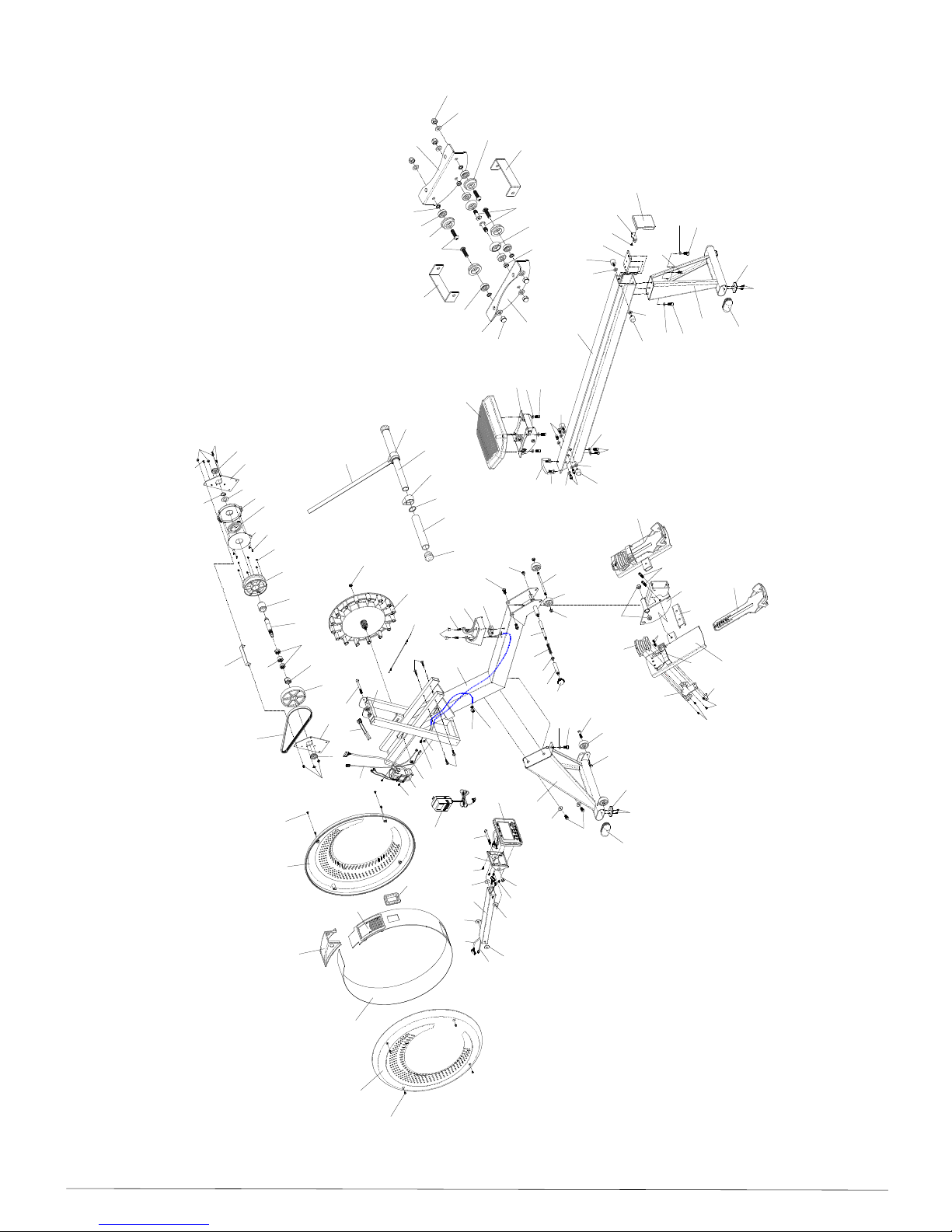
Aa21
A33
A33
A30
A34
E10
A29
F7
F6
A28
A27
A26
B12
B12
B12
B12
C7
C7
C7
C7
A24
A23
A22
A21
B2-11
B2-10
B2-6
B2-7
B2-9
B2-2
B2-4
B2-1
B2-5
B2-3
B2-4
B2-8 B2-2
B2-11
B2-10
B2-3
B2-1
F5
F5
A20
A19
Aa20
A1
A10
A3 A2
A11
A12
A7
A11
A9
A4
A8
A5 A7 A6 B1
B3
B2
B4
B4
B10
B11
B4
B9 B4
B9
B9
B5B8 B7
B6
C1
C4
C2 C3 C6
C5
C4
D1
D2
C2 C3
C4 C4
E2
E1L
E1R
E8
E3
E9
E6
E4
E5
E7
F1
F4
F4 F4
F4 F3
F2
A12
A7
G1
G2
G3
G5
G4
G1
A16 A15 A14L A13
A14R
Aa6 Aa18
Aa17
Aa7 Aa8
Aa9 Aa1Aa11
Aa16
Aa15
Aa16
Aa10
Aa14
Aa5
Aa4
Aa12
Aa13
Aa19
Aa3
Aa1
Aa11
Aa15
Aa2
A25
A25
A10
A10
A6
A17
A18
E7
B9-1
B9-1
B9-1
A30
A31
A32
A26
A31
Assembly
Guide
and
Owner’s
Manual
Page
18
Table of contents
Other Northern Lights Home Gym manuals


