Northern Telecom DMS-100 Series User manual

297-7001-503
DMS-100 Family
DMS VoiceMail
Trouble-locating and alarm-clearing
procedures
SPM 02 Standard 02.02 March 1994


Publication number: 297-7001-503
Product release: SPM 02
Document release: Standard 02.02
Date: March 1994
DMS VoiceMail
Trouble-locating and alarm-clearing procedures
SPM 02
DMS-100 Family
DMS VoiceMail
Trouble-locating and alarm-clearing procedures
Printed in the United States of America
Information is subject to change without notice. Northern Telecom reserves the right to make changes in design or components
as progress in engineering and manufacturing may warrant.
1993, 1994 Northern Telecom
All rights reserved
DMS
,
DMS SuperNode
,
MAP, Meridian, Meridian Mail, and NT are trademarks of Northern Telecom.

297-7001-503 Standard 02.02 March 1994
ii
Publication history
March 1994 Standard 02.02 is the first standard release of the SPM 02 version of this
document. SPM 02 is the second software release for DMS VoiceMail.
February 1994Standard 01.03 is the first standard release of the SPM 01 version of this
document. SPM 01 is the first software release for DMS VoiceMail.

DMS VoiceMail Trouble-locating and alarm-clearing procedures SPM 02
iii
Contents
About this document ix
When to use this document x
How DMS VoiceMail documentation is organized x
References in this document x
What precautionary messages mean xi
Regulatory notices xii
United States installations xii
Canadian installations xiii
System redundancy 1-1
Power 1-1
Multiserver processor node 1-2
Signal processing node 1-3
Telephony interface node 1-4
Disk drives 1-5
T1 spans 1-6
Simplified message desk interface links 1-7
Local maintenance console 1-8
Remote access 1-9
Maintenance principles 2-1
Maintenance model 2-1
Maintenance actions and system events 2-2
MSP maintenance actions 2-2
TIFN maintenance actions 2-7
SPN maintenance actions 2-11
System status and maintenance menu 2-14
Node status screen 2-15
Card status screen 2-16
T1 link status screen 2-17
SMDI link status screen 2-19
SPM cross reference table 2-21
Disk maintenance screen 2-22
SEER operations 2-24
Troubleshooting using SEERs 2-26
Interpreting SEERs 2-26
Example 1 2-26
Example 2 2-27
Hardware database 2-33
Hardware database locations 2-33

iv Contents
297-7001-503 Standard 02.02 March 1994
Alarms 2-37
Out-of-Service diagnostics 2-39
68K diagnostics 2-39
T1 diagnostics 2-39
VP12 diagnostics 2-40
Bus controller diagnostics 2-40
On-line diagnostics 2-41
Booting the system 3-1
Booting up procedures 3-1
68K node loading 3-2
Booting problems 3-3
Multiserver processor node 4-1
68K card 4-1
Bus controller card 4-1
68K transition module 4-1
Bus controller transition module 4-1
MSP configurations 4-1
Maintenance exceptions 4-3
Cannot complete MSP switchover 4-3
Cannot enable node 4-4
Cannot disable node 4-4
Out-of-service diagnostics fail on 68K card 4-5
Out-of-service diagnostics fail on bus controller card 4-5
System response 4-6
Lost communication through the terminal 4-6
Node stuck in faulty state 4-6
Node stuck in loading state 4-6
Node oscillating between InService/InSvStandby and OutOfService 4-7
Node continues to reboot 4-7
Node cannot boot from tape 4-7
Node recovery 4-7
Recovering the entire system 4-7
Recovering the InSvStandby MSP 4-7
Signal processing node 5-1
68K card 5-1
VP12 card 5-1
68K transition module 5-1
Maintenance exceptions 5-2
Cannot enable node 5-2
Cannot enable card 5-3
Cannot enable DSP channel 5-4
Out-of-service diagnostics on card fail 5-4
Cannot disable node 5-4
Cannot disable card 5-4
Cannot disable channel 5-5
Channels do not reactivate properly after a card replacement 5-5
System response 5-6
Voice card/DSP port problems 5-6

Contents v
DMS VoiceMail Trouble-locating and alarm-clearing procedures SPM 02
Accidental removal of the 68K transition module 5-6
Node stuck in loading state 5-6
DSP port stuck in pending state 5-6
DSP stuck in loading state 5-7
DSP port stuck in out-of-service state 5-7
DSP port stuck in faulty state 5-7
DSP port unconfigured 5-7
DSP port stuck in NoResources state 5-7
Node rebooting 5-7
Noisy recorded message or noisy session 5-8
Disk failure 5-8
Call connected but no voice 5-8
Incoming call OK but not outcalling 5-8
Outcalling OK but no incoming call 5-8
Node recovery 5-9
Telephony interface node 6-1
68K card 6-1
T1 card 6-1
Modem transition module 6-1
T1 transition module 6-1
Maintenance exceptions 6-2
Cannot enable node 6-2
Cannot enable card 6-3
Cannot enable T1 link 6-5
Cannot enable T1 channel 6-7
Cannot enable SMDI link 6-8
Out-of-service diagnostics on 68K card fail 6-9
Out-of-service diagnostics on T1 card fail 6-9
Cannot disable node 6-10
Cannot disable card 6-11
Cannot disable T1 span 6-11
Cannot disable T1 channel 6-12
Cannot disable SMDI link 6-12
Symptom response 6-13
Node stuck in loading state 6-13
Channel stuck in pending state 6-14
Channel stuck in loading state 6-15
Channel stuck in out-of-service state 6-16
Channel stuck in faulty state 6-17
Channel stuck in unconfigured state 6-17
Channel stuck in no-resource state 6-18
Node rebooting 6-19
T1 link alarms 6-20
SMDI link alarms 6-24
Node recovery 6-24
Disks and tape drives 7-1
Interpreting Class 66 disk managing SEERs 7-1
Class 6602 7-3
Class 6603 7-4

vi Contents
297-7001-503 Standard 02.02 March 1994
Class 6604 7-5
Class 6605 7-6
Class 6606 7-6
Replacing and resynchronizing disks 7-6
Tape drive errors 7-7
Peripherals and links 8-1
Local terminals 8-1
Multiple administration terminals 8-2
Remote terminals 8-3
Local printers 8-4
No printer output 8-4
Printer alarms 8-4
Backup printers 8-5
No printer output 8-5
Printer alarms 8-5
SMDI links 8-6
Link bounces up and down constantly 8-6
Link cannot be brought up 8-6
If the system shows an alarm 8-7
Link up for a short time and then down 8-9
Link goes down when idle 8-9
DMS SMDI shutdown behavior 8-9
T1 links 8-10
All channels are not working 8-10
Some channels are not working 8-11
Multiple T1 links are not working 8-11
Cabinet and I/O connections 9-1
Frame supervisory panel 9-1
Input/output panel 9-1
Input/output panel interconnections 9-1
Input/output panel daughter board replacement 9-4
Input/output panel replacement 9-4
Input/output cabling 9-5
Input/output cable identification 9-5
Input/output cable replacement 9-11
Intracabinet cabling 9-11
Input/output cable identification 9-11
Input/output cable replacement 9-14
How the Meridian Mail bus is configured 9-16
Bus extender cable replacement 9-16
Bus extender transition module replacement 9-17
Bus terminator transition module replacement 9-17
Primary shelf bus terminator symptoms 9-17
Cannot boot from a cold start 9-17
Nodes unload while in service 9-17
Secondary shelf bus terminator symptoms 9-18
Nodes time-out booting 9-18
Nodes unload while in service 9-18

Contents vii
DMS VoiceMail Trouble-locating and alarm-clearing procedures SPM 02
Other bus terminator symptoms 9-19
No SEERs 9-19
Local terminal lockup 9-19
Critical alarm 9-19
Bus extender transition module symptoms 9-20
Nodes unload on secondary shelf 9-20
Loss of voice 9-20
Remote view bootup diagnostics 10-1
Setting up the modem 10-1
Dialing into the SPM 10-1
Modem BIX tip and ring pairs for MSPs and SPNs 10-2
Online recovery 11-1
List of figures
Figure 1-1 SPM shelf power division 1-1
Figure 1-2 MSP pair 1-2
Figure 1-3 SPN pair 1-3
Figure 1-4 TIFN pair 1-4
Figure 1-5 Basic disk drive configuration 1-5
Figure 1-6 T1 span termination 1-6
Figure 1-7 SMDI link termination 1-7
Figure 1-8 Local maintenance console connectivity 1-8
Figure 1-9 Direct dial-up to an SPM 1-9
Figure 2-1 DMS VoiceMail maintenance model 2-1
Figure 2-2 Boot sequence 2-3
Figure 2-3 Disabling MSPs 2-5
Figure 2-4 Enabling MSPs 2-6
Figure 2-5 Enabling T1 spans 2-8
Figure 2-6 Disabling T1 spans 2-9
Figure 2-7 Enabling and disabling T1 channels 2-10
Figure 2-8 Enabling and disabling a VP12 card 2-12
Figure 2-9 Enabling and disabling a DSP port 2-13
Figure 2-10 System Status and Maintenance menu 2-14
Figure 2-11 Node Status screen 2-15
Figure 2-12 Card Status screen 2-16
Figure 2-13 T1 Link Status screen 2-18
Figure 2-14 SMDI Link Status screen 2-20
Figure 2-15 SPM Cross Reference Table screen 2-21
Figure 2-16 Disk Maintenance screen 2-22
Figure 2-17 Disk Pair Status screen 2-23
Figure 2-18 System Event and Error Reports screen 2-24
Figure 2-19 Report screen 2-25
Figure 2-20 Parts of a SEER 2-25
Figure 2-21 T1 Link Status screen 2-27
Figure 2-22 T1 Link Status screen 2-28
Figure 2-23 T1 Link Status screen 2-30
Figure 2-24 T1 Channel Status screen 2-31
Figure 2-25 T1 Link Status screen 2-32
Figure 2-26 Basic alarm components 2-38

viii Contents
297-7001-503 Standard 02.02 March 1994
Figure 6-1 TIFN cable sets 6-20
Figure 7-1 Node numbers and corresponding disk and pack numbers 7-2
Figure 9-1 Input/output panel locations - rear SPM view 9-2
Figure 9-2 Input/output connectors 9-3
Figure 9-3 Input/output cable identification 9-6
Figure9-4 Internal backplane cable connections for shelf 26 9-7
Figure 9-5 Internal backplane cable connections for shelf 39 9-8
Figure 9-6 Internal backplane cable connections for shelf 00 9-9
Figure 9-7 Internal back plane cable connections for shelf 13 9-10
Figure 9-8 MMBus physical configuration 9-16
List of procedures
Procedure 6-1 Cannot enable node 6-2
Procedure 6-2 Cannot enable card 6-3
Procedure 6-3 Cannot enable T1 link 6-5
Procedure 6-4 Cannot enable T1 channel 6-7
Procedure 6-5 Cannot enable SMDI link 6-8
Procedure 6-6 Out-of-service diagnostics on 68K card fail 6-9
Procedure 6-7 Out-of-service diagnostics on T1 card fail 6-9
Procedure 6-8 Cannot disable node 6-10
Procedure 6-9 Cannot disable card 6-11
Procedure 6-10 Cannot disable T1 span 6-11
Procedure 6-11 Cannot disable T1 channel 6-12
Procedure 6-12 Cannot disable SMDI link 6-12
Procedure 6-13 Node stuck in loading state 6-13
Procedure 6-14 Channel stuck in pending state 6-14
Procedure 6-15 Channel stuck in loading state 6-15
Procedure 6-16 Channel stuck in out-of-service state 6-16
Procedure 6-17 Channel stuck in faulty state 6-17
Procedure 6-18 Channel stuck in no-resource state 6-18
Procedure 6-19 Node rebooting 6-19
Procedure 6-20 T1 link alarms 6-20
List of tables
Table 2-1 HWLOC node information 2-34
Table 2-2 HWLOC channel information 2-35
Table 2-3 HWLOC DSP port information 2-36
Table 3-1 Booting problems 3-3
Table 8-1 Mapping of SPNs to TIFNs 8-2
Table 9-1 Preparing to remove I/O panel daughter boards 9-4
Table 9-2 Input/output cable identification 9-11
Table 9-3 Recommended I/O cable replacement procedures 9-14
Table 10-1 Modem tip and ring pairs (shelf 26 right) 10-2
Table 10-2 Modem tip and ring pairs (shelf 26 left) 10-2
Table 10-3 Modem tip and ring pairs (shelf 39 left) 10-3
Table 10-4 Modem tip and ring pairs (shelf 39 right) 10-3

DMS VoiceMail
Trouble-locating and alarm-clearing procedures
SPM 02
ix
ProcNum1
TabNum1
FigNum1
About this document
This document provides information about the DMS VoiceMail system, its
subsystems, and procedures for locating troubles and clearing alarms. The
procedures are designed for first-line and secondary support maintenance
personnel in an operating company.
The document is structured in the following chapters:
System redundancy discusses the principal subsystems, peripherals, and
links that comprise the DMS VoiceMail system and how redundancy has
been incorporated as part of the product to provide reliable service.
Maintenance principles describes the basic maintenance model used by
DMS VoiceMail and the various maintenance tools and indicators that are
available to monitor system performance.
Booting the system provides booting up procedures and information on what
to look for if problems are encountered during the booting up sequence.
Multiserver processor node provides a summary description of the
multiserver processor node and procedures for resolving troubles.
Signal processing node provides a summary description of the signal
processing node and procedures for resolving troubles.
Telephony interface node provides a summary description of the telephony
interface node and procedures for resolving troubles.
Disks discusses how to interpret SEERs that indicate problems with the disk
drives.
Peripherals and links provides procedures for resolving problems with
peripherals and links in a DMS VoiceMail system.
Cabinet and I/O connections discusses where to locate information on
clearing frame supervisory panel faults, how to resolve cabling, and
Meridian Mail bus troubles.

xAbout this document
297-7001-503 Standard 02.02 March 1994
When to use this document
This document is written for all offices where DMS VoiceMail is deployed.
More than one version of this document may exist. To determine whether
you have the latest version of this document, check the release information
in DMS-100 Family Guide to Northern Telecom Publications,NTP
297-1001-001.
How DMS VoiceMail documentation is organized
This document is part of DMS VoiceMail documentation that supports the
Northern Telecom line of DMS VoiceMail products. DMS VoiceMail
documentation is a subset of the DMS-100 Family library.
The DMS-100 Family library is structured in numbered layers, and each
layer is associated with an NT product. To understand DMS VoiceMail
products, you need documents from the following layers:
•DMS-100 Family basic documents in the 297-1001 layer
•DMS VoiceMail documents in the 297-7001 layer
DMS VoiceMail documents and other documents that contain related
information are listed in “Finding DMS VoiceMail information” in DMS
VoiceMail Product Guide (NTP 297-7001-010).
References in this document
The following documents are referred to in this document.
Number Title
297-7001-010
DMS VoiceMail Product Guide
297-7001-300
DMS VoiceMail System Administration Guide
297-7001-502
DMS VoiceMail Card Replacement Procedures
About this document xi
DMS VoiceMail
Trouble-locating and alarm-clearing procedures
SPM 02
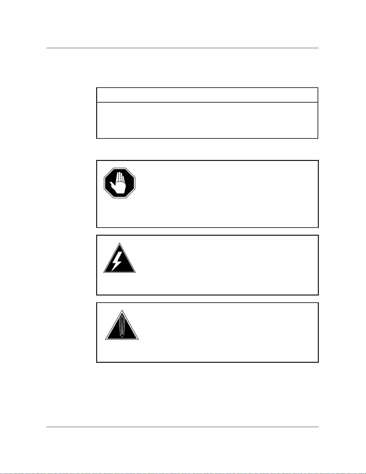
What precautionary messages mean
Danger, warning, and caution messages in this document indicate potential
risks. These messages and their meanings are listed in the following chart.
Message Significance
DANGER Possibility of personal injury
WARNING Possibility of equipment damage
CAUTION Possibility of service interruption or degradation
Examples of the precautionary messages follow.
DANGER
Risk of electrocution
The inverter contains high voltage lines. Do not open the front
panel of the inverter unless fuses F1, F2, and F3 have been
removed first. Until these fuses are removed, the high voltage
lines inside the inverter are active, and you risk being
electrocuted.
WARNING
Damage to backplane connector pins
Use light thumb pressure to align the card with the connectors.
Next, use the levers to seat the card into the connectors. Failure
to align the card first may result in bending of the backplane
connector pins.
CAUTION
Loss of service
Subscriber service will be lost if you accidentally remove a card
from the active unit of the peripheral module (PM). Before
continuing, confirm that you are removing the card from the
inactive unit of the PM.

xii About this document
297-7001-503 Standard 02.02 March 1994
Regulatory notices
United States installations
The following regulatory notices pertain to installations in the United States
of America:
1The Northern Telecom service peripheral module complies with Part 68
of the FCC rules. On the inside door of the cabinet is a label that
contains, among other information, the FCC registration number and
ringer equivalence number (REN) for this equipment. If requested, this
information must be provided to the telephone company.
2The FCC regulation label includes the REN. This number represents the
electrical load that will be applied to your telephone line once an SPM
modem port is connected to the network. The telephone line serving
your premises will not operate properly if the total ringer load exceeds
the capability of your telephone company central office equipment. If
you desire to know the total REN allowed for your telephone line, call
your telephone company and they will inform you. Normally, an SPM
modem port should not share the line with any other device.
If your Northern Telecom SPM causes harm to the telephone network,
the telephone company may disconnect your service temporarily. The
telephone company may ask you to disconnect the equipment from the
network until the problem has been corrected or you are sure that the
equipment is not malfunctioning. It is possible they will notify you in
advance, but if the advance notice is not practical, you will be notified as
soon as possible. You will be advised of your right to file a complaint
with the FCC.
Your telephone company may make changes in its facilities, equipment,
operations or procedures that could affect proper operation of your
equipment. If they do, you will be given advance notice so as to give
you an opportunity to maintain uninterrupted service.
If you experience trouble with your Northern Telecom SPM equipment,
contact your authorized distributor or service center in the USA for
repair or warranty information. If you do not know how to contact your
distributor, call 1-800-NORTHERN.

About this document xiii
DMS VoiceMail
Trouble-locating and alarm-clearing procedures
SPM 02
Canadian installations
The following regulatory notices pertain to installations in Canada:
3The Canadian Department of Communications label identifies certified
equipment. This certification means that the equipment meets certain
telecommunications network protective, operational and safety
requirements. The Department does not guarantee the equipment will
operate to the user’s satisfaction.
Before installing this equipment, users should ensure that it is
permissible to be connected to the facilities of the local
telecommunications company. The equipment must also be installed
using an acceptable method of connection. The customer should be
aware that compliance with the above conditions may not prevent
degradation of service in some situations.
Repairs to certified equipment should be made by an authorized
Canadian maintenance facility designated by the supplier. Any repairs or
alterations made by the user to this equipment, or equipment
malfunctions, may give the telecommunications company cause to
request the user to disconnect the equipment.
Users should ensure for their own protection that the electrical ground
connections of the power utility, telephone lines and internal metallic
water pipe system, if present, are connected together. This precaution
may be particularly important in rural areas.
DANGER
Risk of electrocution
Users should not attempt to make such connections themselves,
but should contact the appropriate electrical inspection authority,
or electrician, as appropriate.
4 The load number (LN) assigned to each terminal device denotes the
percentage of the total load to be connected to a telephone loop which is
used by the device, to prevent overloading. The termination on a loop
may consist of any combination of devices subject only to the
requirement that the sum of the LNs of all the devices does not exceed
100.
If you experience trouble with your Northern Telecom SPM equipment,
contact your authorized distributor or service center in Canada for repair
or warranty information. If you do not know how to contact your
distributor, call 1-800-NORTHERN.

xiv About this document
297-7001-503 Standard 02.02 March 1994

DMS VoiceMail
Trouble-locating and alarm-clearing procedures
SPM 02
1-1
System redundancy
Power For power distribution purposes, each shelf of the service peripheral module
(SPM) is divided into two halves between card slots 19 and 20. Each
half-shelf is powered by two power converters that are supplied by the A
and B central office power feeds.
Figure 1-1 illustrates the division of power for an SPM shelf that occurs
between card slots 19 and 20.
Figure 1-1
SPM shelf power division
M
S
P
M
S
P
S
P
N
S
P
N
T
I
F
N
T
I
F
N
S
P
N
S
P
N
9
X
9
1
A
B
9
X
9
1
A
B
9
X
9
1
A
B
9
X
9
1
A
B
9
X
9
1
A
B
9
X
9
1
A
B
9
X
9
1
A
B
9
X
9
1
A
B
Electronics
shelf
Disk shelf
Hard
disk
drive
19 20
19 20
Note: Middle disk drives are powered from the left power converters.

1-2 System redundancy
297-7001-503 Standard 02.02 March 1994
Multiserver processor node
DMS VoiceMail uses a pair of multiserver processors (MSPs) to provide
system redundancy. The primary MSP has the active bus controller.
Multiserver programs are distributed to both MSPs. When the active MSP
fails, bus control passes to the second MSP and the appropriate multiserver
programs are restarted.
Figure 1-2 illustrates a pair of MSPs.
Figure 1-2
MSP pair
MSP 1 MSP 2
Disk
drive
Disk
drive

System redundancy 1-3
DMS VoiceMail
Trouble-locating and alarm-clearing procedures
SPM 02
Signal processing node
A DMS VoiceMail subscriber is normally associated with one signal
processing node (SPN). SPNs are configured in pairs. If one SPN fails, the
overall system capacity is diminished. However, since SPNs are paired (that
is SPNs 1-2, 3-4, 5-6, etc.), all subscribers on a failed SPN can still gain
access to their mailboxes through the other SPN.
The SPN consists of three types of cards:
•one 68K card
•two VP12 cards
•one 68K transition module
The loss of a VP12 card in an SPN results in 12 channels being lost.
However, VP12 cards can be replaced while an SPN remains in service.
This allows the affected SPN to continue providing 12 channels of service
until the failed VP12 card is replaced.
The loss of a 68K card in an SPN results in all 24 channels being lost.
Figure 1-3 illustrates a pair of SPNs.
Figure 1-3xxx
SPN pair
SPN 1 SPN 2
Disk
drive
Disk
drive

1-4 System redundancy
297-7001-503 Standard 02.02 March 1994
Telephony interface node
The telephony interface node (TIFN) consists of a 68K card and a T1 card.
TIFNs are configured in redundant pairs. If the primary TIFN fails, the T1
spans and SMDI links that terminate on the primary TIFN are automatically
shifted to the secondary TIFN.
Figure 1-4 illustrates a pair of TIFNs and the redundant T1 and SMDI links
from the primary TIFN to the secondary TIFN.
Figure 1-4
TIFN pair
Secondary
TIFN
Primary
TIFN
T1
spans SMDI
links
Other manuals for DMS-100 Series
9
Table of contents
Other Northern Telecom Voicemail manuals


