Northline Express DuraVent DuraLiner SDL User manual

1
THESE INSTALLATION AND OPERATION INSTRUCTIONS
COVER DURALINER MASONRYRELININGSYSTEM
A MAJOR CAUSE OF CHIMNEY RELATED FIRES IS
FAILURE TO MAINTAIN REQUIRED CLEARANCES (AIR
SPACES) TO MASONRY MATERIALS. IT IS OF THE
UTMOST IMPORTANCE THAT THIS DURALINER
CHIMNEY SYSTEM BE INSTALLED ONLY IN
ACCORDANCE WITH THESE INSTRUCTIONS.
Readthroughalltheseinstructionsbefore beginning your installation. Failure
to install this DuraLiner product as described in these instructions will void
the manufacturer’s warranty and may have an effect on your homeowner’s
insurance and UL/ULC listing status. Keep these instructions for the future
reference.
APPLICATIONAND LISTING
DuraLiner is a double-wall, insulated all-fuel reliner for masonry chimneys.
DuraLiner is listed and approved for installation with zero clearance between
the liner and masonry, plus zero clearance between the masonry and
combustibles. The DuraLiner lining system is intended for field installation
into new or existing masonry chimney used for natural draft venting of gas,
liquid and solid-fuel fired residential type appliances in which the maximum
continuous flue gas outlet temperatures do not exceed 1000OF/538OC (UL
1777) or 1200OF/650OC (ULC S635, ULC S640). DuraLiner is listed to the
UL 1777 standard for Chimney Liners, under the listing file number
MH14420. DuraLiner is also listed to the Canadian Standards ULC S635
and ULC S640 for lining new and existing masonry chimneys, under the
listing file number CMH1329. DuraLiner meets all the thermal, mechanical
andmaterial requirements ofthe UL1777,ULCS635, &ULC S640 standards.
DURALINER (SDL)
6"-8" DIAMETER
(ROUND & OVAL)
INSTALLATION INSTRUCTIONS MH14420 CMH1329
NorthlineExpress.com
http://www.northlineexpress.com
Toll-Free 1-866-667-8454
2
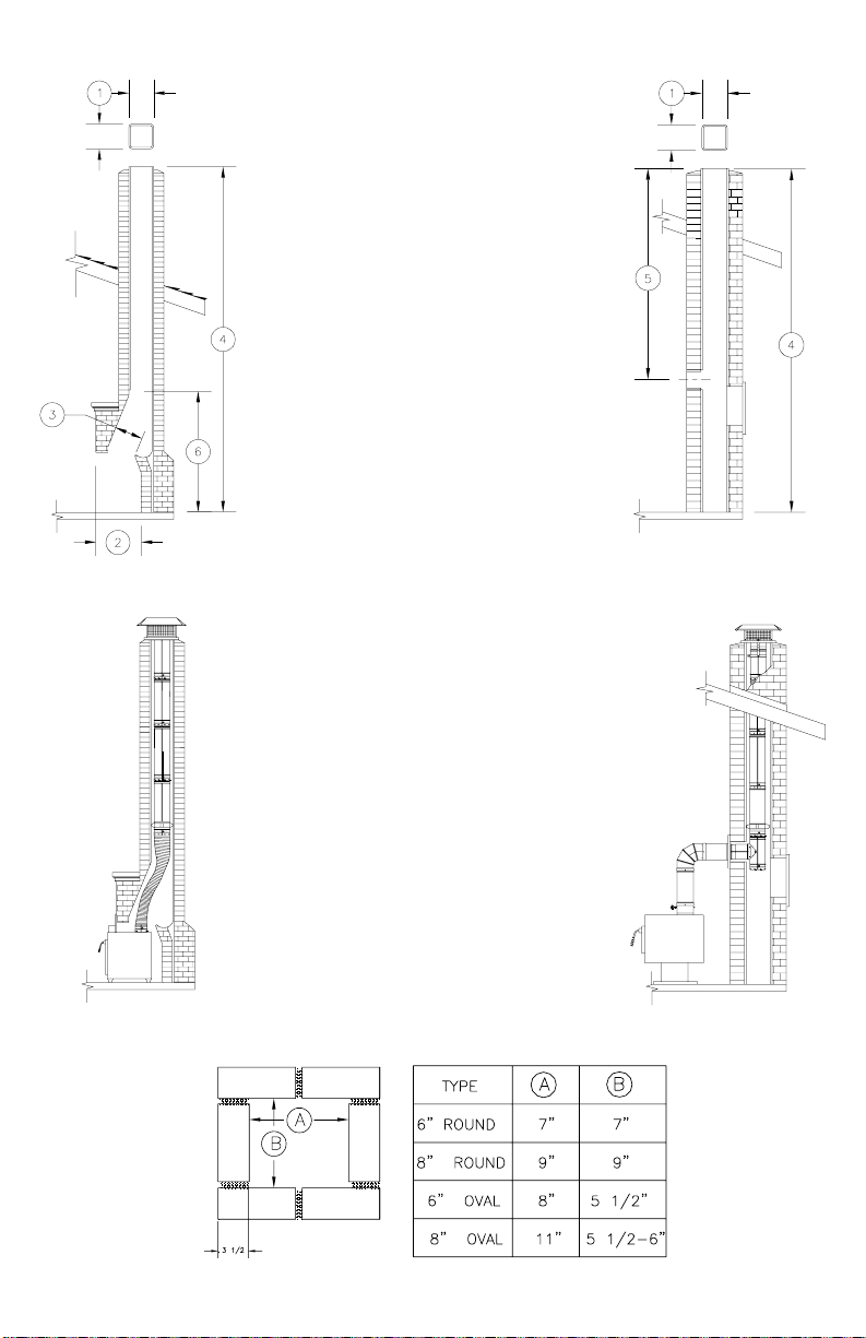
Fig. 2a Chart 2a Fig. 2
Fig. 1
IMPORTANT MEASUREMENTS
1. Flue Size I.D.
a.______________
2. Opening of Fireplace
a. Height_________
b. Width _________
c. Depth _________
3. Damper Opening
a.Length_________
b.Width_________
4. Total Chimey and
Fireplace Height
a.______________
5. Total Chimney Height
to Tee Opening
a._______________
6. Height to First Tile
a._______________
7. Height of Stove or Insert
a. _______________
NorthlineExpress.com
http://www.northlineexpress.com
Toll-Free 1-866-667-8454

3
TABLE OF CONTENTS
APPLICATIONAND LISTING..............................................................1
GENERALINSTALLATION INSTRUCTIONS ..................................5
MASONRYTHIMBLEAND WALL PENETRATIONS ....................11
EXTEND-A-CAPINSTALLATION .....................................................13
INSTALLING INSULATION SLEEVES .............................................16
DURALINER MAINTENANCE INSTRUCTIONS ...........................18
WARRANTY ...........................................................................................20
AN IMPORTANT MESSAGEABOUTRELININGYOUR CHIMNEY
1. Have a professional installer thoroughly clean, and install your new
appliance and relining system.
2. Determine condition of creosote buildup in masonry flue, always clean
before relining. Any tar glaze creosote buildup must be removed prior to
relining the chimney.
3. Determine condition of masonry fireplace and chimney. See that they
meet code requirements. The chimney should be checked for cracked, loose
or missing bricks, mortar, or other materials that could inhibit a correct
installation of the liner system. Make necessary repairs before relining.
4. The air space clearances between the masonry chimney exterior and
combustible materials should be checked to verify that the chimney is in
accordance with the clearance specifications of 1) the NFPA; 2) other
applicable building codes; or 3) these instructions (DuraLiner is approved
for 0” clearance if installed in accordance with these instructions).
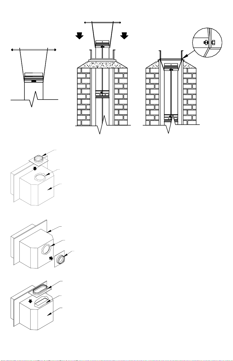
5. Determine if your setup is an open hearth (Figure 1) or tee installation
(Figure 2). Also determine the available size of your chimney (Figure 2a)
and the corresponding allowable DuraLiner size. (Chart 2a)
6. If you have an open hearth setup, verify your flue size, and the fireplace
opening and depth before you purchase your appliance and reliner. (See
Figure 1)
NorthlineExpress.com
http://www.northlineexpress.com
Toll-Free 1-866-667-8454

4
7. If you have a tee installation setup, verify your flue size and chimney
height from tee, before you purchase your appliance and reliner. (Figure 2)
8. After selection of proper size appliance, determine the correct size of
DuraLiner and Stove Connector to the appliance. (Follow stove
manufacturer’s recommendations). There are three different types of
connections: (See Figure 3).
a. Round, for top flue exit.
b. Round, for rear flue exit.
c. Rectangular, for top flue exit
9. Chimney flue size (Figure 1) determines the size top you select. (See
catalog for details).
10. Necessary tools and equipment you may need:
Ladder Vicegrips
Safety Glasses Light Rope
Gloves Snips
Tape Measure Drill & 5/32" Twist Drill Bit
Hammer Metal Saw
Screwdriver Pop Rivet Gun
High Temperature Waterproof Sealant
Make sure all equipment is in good condition.
11. Safety Tips:
Do not go on roof when wet or icy.
Sheet metal parts have sharp edges, wear gloves.
Safety Glasses.
Safety Hat.
Practice good workmanship. Sloppy work could jeopardize your installation.
Fig. 3
CBA
NorthlineExpress.com
http://www.northlineexpress.com
Toll-Free 1-866-667-8454
5
12. Clearances: Simpson Dura-Vent’s DuraLiner is
listed by Underwriters Laboratories (UL & ULC) as
a liner for listed all-fuel burning appliances.
DuraLiner is designed and listed for installation in
masonry chimneys only. The minimum clearance
from pipe to masonry construction is “0”. Never
fill any required clearance (air space) with
combustible or noncombustible materials.
DuraLiner shall be sized not less than that specified
in the appliance manufacturer’s instructions.
13. Permits: Contact your local building official or
fire department regarding permits, restrictions, and
installation inspection in your area.
GENERALINSTALLATION INSTRUCTIONS
Choose an appliance that is listed by a recognized
testing laboratory.
a. Follow the appliance manufacturer’s
instructions.
b. Connect only one flue liner per appliance.
c. DO NOT mix or match with other products
or improvise solutions. (You may void
warranties.) DO NOT modify parts.
d. Follow the appliance manufacturer’s
instructions and manual for maximum
efficiency and safety. Over firing can
damage the appliance and lining system.
Follow these basic assembly instructions when
installing DuraLiner in the open hearth installation
(Figure 1). For tee installations, refer to the Tee
Installation section of these instructions. The oval
liner fits together in the same manner as the round
liner.
STEPONE: If needed, remove theexisting damper
from your fireplace to allow liner to fit.
Fig. 4
TOP
SLIP
CONNECTOR
SECONDARY
TOP
SCREEN
FRAME
HANGER
DAMPER
SMOKE
SHELF
NorthlineExpress.com
http://www.northlineexpress.com
Toll-Free 1-866-667-8454
6
Your fireplace insert or stove and DuraLiner are designed to work without
your existing damper. In order to install the DuraLiner, you must remove the
damper and in some cases part of the smoke shelf, to allow DuraLiner to pass
through this area freely. Note: DuraLiner flex pipe is available in both round
and oval shapes to ease installation.
Now that the old damper assembly and part of the smoke shelf has been
removed, the chimney and fireplace should be free from obstructions.
STEPTWO: The DuraLiner system is held in place by the framework at the
top of the chimney is designed to support the weight of a relining system up
to 50 feet. The minimum height of system must be at least 10-feet to insure
proper drafting performance.
The top comes assembled. You must take the top apart to get the bottom
frame in place. The top has six major components: Top, Screen, Secondary
Top, Frame, Slip Connector and Hanger. (See Figure 4) Place frame on top
of masonry chimney, the weight of the DuraLiner will hold the top in place.
We also provide screws that may be attached to bottom of frame and attached
tile. (See Figure 5).
STEP THREE: All DuraLiner pipe (flex and rigid) has male and female
connectorswith (4) pre-punched holesandslots that lineupand are connected
with stainless steel pop rivets. Do not use screws. When connecting sections
of flex pipe, it is necessary to first align the holes with the slots, and then drill
through the flex pipe with a 5/32” (4 mm) diameter twist drill bit. Next,
install the pop rivets. Drilling is not needed to connect sections of rigid pipe.
Connectfirst rigid sectionof DuraLinerontop offlex section with(4) stainless
steel pop rivets.
Note: The DuraLiner flex sections
can be easily insulated with the
Two-Ply Insulation Sleeve. This
blanket insulating sleeve permits
complete flexibility. It is held in
place by simple strap clamps that
aresecured withboltand nutat each
Fig. 5
FRAME
SCREWS SEALANT
NorthlineExpress.com
http://www.northlineexpress.com
Toll-Free 1-866-667-8454
7
end of DuraLiner flexible pipe lengths. Refer to the Insulation Sleeve
Instruction section.
Fromthe stove,up throughthe damperto thefirstflue tile,it isNOT mandatory
touse anInsulation Sleeve.Abovethe firstflue tile,flex pipemust beinsulated.
(NOTE: For improved draft and fire safety, we recommend the use of an
insulation sleeve on all flex pipes.)
After pipe is riveted together, lower through the Frame of DuraLiner Top and
hold in position. Each DuraLiner pipe section is then riveted and lowered
down the chimney. This procedure is repeated until the flex section reaches
the smoke shelf area. As the pipe is being lowered further down, bend the
flex pipe to fit through the damper. (See Figure 7a and 7b)
STEP FOUR: Before you rivet the last section of pipe in place, attach the
hanger to the last section of pipe just below the bead. (See Figure 8)
Attach the hanger strap holder to the last hole on the strap. (See Figure 8)
Lower DuraLiner to final position. (See Figure 9) If appliance has top flue
exit, hold approximately ½” above connector. (See Figure 13) If appliance
has rear flue exit, line up branch of tee with connector. (See Figure 16)
Fig. 7aFig. 6 Fig. 7b
6” OR 8”
ROUND
RIGID PIPE
(VARIOUS
LENGTHS)
6” OR 8”
FLEX PIPE
(VARIOUS
LENGTHS)
RIGID PIPE
FLEX PIPE
RIGID PIPE
FLEX PIPE
NorthlineExpress.com
http://www.northlineexpress.com
Toll-Free 1-866-667-8454
8
Attach hanger strap to holes in chimney top
frame. Secure with nut and bolt. (See Figure
10)
STEP FIVE: Stove top connector - round
and oval. Attach the proper Stove Connector
to your insert or stove. (See Figure 3) The
DuraLiner round Stove Connector fits either
a top vented found flue appliance or a rear
ventedroundflue appliance. Place the proper
sized connector over the flue exit and mark
onthe insert orstovethe locations ofthe holes
where the connector will be attached. (See
Figure 11a or 11b) Drill and tap hole in top
orrear of applianceor use selftapping screws.
Before attaching permanently, put a bead of
high temperature sealant between stove
connector and insert. (See Figure 11a and
11b)
The DuraLiner oval Stove Connector fits on
top vented appliances or inserts with oval or
rectangularopenings. (See Figure 12) Attach
same as in round openings. (See Figure 11a)
Fig. 8
Fig. 9 Fig. 10
Fig. 11a
Fig. 11b
Fig. 12
HANGER STRAP HOLDER
HANGER
BEAD ON
RIGID
HANGER STRAP
HOLDER
HANGER
FRAME
NUT/BOLT
BEND
ROUND STOVE
CONNECTOR
HIGH
TEMPERATURE
SEALANT
STOVE
INSERT
ROUND
STOVE
CONNECTOR
HIGH
TEMPERATURE
SEALANT
STOVE
INSERT
OVAL STOVE
CONNECTOR
HIGH
TEMPERATURE
SEALANT
STOVE
INSERT
NorthlineExpress.com
http://www.northlineexpress.com
Toll-Free 1-866-667-8454

9
STEP SIX: Connect stove or insert to DuraLiner. When connecting
DuraLiner to top-exiting appliance outlets, follow this procedure. After stove
or insert has been set in proper location, pull flex pipe down over Stove
Connector and pop rivet or screw together. (See Figure 1) If the flex pipe
does not provide sufficient height adjustment, further adjustment may be
made by selecting a different set of holes on the DuraLiner Hanger at the top
of the system. The Slip Connector will accommodate up to 10" adjustment.
Note: If you have a round flue outlet on your stove, and you have used Oval
Flex or Oval-To-Round flex through the damper area, a 14" Round-To-Oval
flexible pipe adapter will be required for the stove connection. (See Catalog)
If stove or insert has a round rear exit, attach round or oval Tee to bottom of
flex pipe. (See Figure 14) Line up branch of Tee with stove outlet.
Fig. 13
Fig. 14 Fig. 15
FLEX PIPE
1/2”
STOVE
CONNECTOR
POP RIVET OR
SCREW FLEX
PIPE TO STOVE
CONNECTOR
FLEX PIPE
OVAL OR
ROUND
RIGID TEE
OVAL OR
ROUND
BRANCH
OF TEE REMOVABLE
TEE CAP
ADJUSTMENT
FLEX PIPE
OVAL OR
ROUND
RIGID TEE
OVAL OR
ROUND
ADJUSTABLE SLEEVE
(MIN. OVERLAP 2”)
TEE CAP
NorthlineExpress.com
http://www.northlineexpress.com
Toll-Free 1-866-667-8454

10
When branch of tee is alligned with rear exit of
appliance, attach DuraLiner Adjustable Sleeve to
branch. The Adjustable Sleeve has pre-formed
buttons. (See Figure 15) The buttons snap into
branch ring. Slide stove or insert into proper
position. Adjust pipe and snap into back of stove.
SecureAdjustableSleeve in final position withsheet
metal screws. Rear flue exit should look like Figure
16.
STEP SEVEN: Now you are ready to do the final
top assembly. Take the slip connector and attach to
Secondary Top. This is held in place by pre-formed
buttons. (NOTE: with oval pipe the Slip Connector
pipe must be attached to the Secondary Top with
pop rivets in four pre-punched holes.) (See Figure
17) When this is done, slide Slip Connector into
DuraLiner and over chimney top Frame. Attach
Secondary Top to frame using eight screws. (See
Figure 18)
After Secondary Top is attached to Frame, slide
Screen into position between legs of Frame
(optional). Put Top on (4) legs, line up prepunched
holes and bolt firmly into position. (See Figure 19)
Fig. 17
Fig. 18
Fig. 19
SECONDARYTOP
PRE-FORMED
BUTTONS
SLIP
CONNECTOR
SECONDARY
TOP
FRAME
SLIP
CONNECTOR
TOP
SCREEN
LEGS
SCREWS
SEALANT
Fig. 16
FLEX PIPE
OVAL OR
ROUND
ADJUSTABLE
SLEEVE (MIN.
OVERLAP 2”)
STOVE
CONNECTOR
RIGID TEE
OVALOR
ROUND
NorthlineExpress.com
http://www.northlineexpress.com
Toll-Free 1-866-667-8454

11
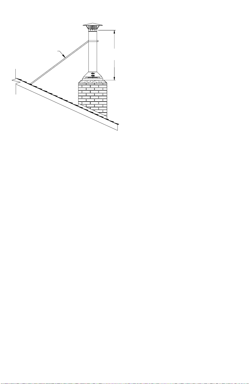
Note: National Fire Protection
Association standard #211 states;
“Chimneys shall extend at least three
feet above the highest point where
they pass through roof of a building
and at least two feet higher than any
portion of a building within ten feet.”
(See NFPA 211 Example)
MASONRYTHIMBLEAND WALLPENETRATIONS
Follow these basic assembly instructions when installing DuraLiner in a Tee
installation, as shown in Figure 2. (Note: Wall penetration assemblies shall
not be located directly behind a heating appliance.)
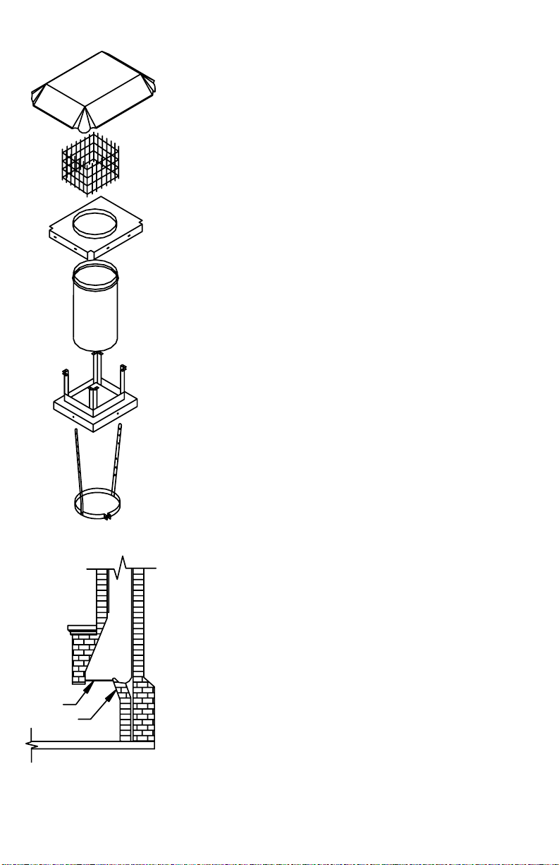
STEPONE: If a Masonry Thimble is used as a wall pass through for a Tee
installation, you must maintain proper clearances to combustibles from the
connector pipe. (See Figure 20)
STEP TWO: All DuraLiner pipe, flex or rigid, has male and female
connectors with prepunched holes and slots that line up and are connected
with stainless steel pop rivets. Do not use screws. When connecting sections
of flex pipe, it is necessary to first align the holes with the slots, and then drill
through the flex pipe with a 5/32” (4 mm) diameter drill. Next, install the
pop rivets. Drilling is not needed to connect sections of rigid pipe. Connect
COMBUSTIBLE
*18”
*18” MINIMUM
CLEARANCE SINGLE-WALL
PIPE TO COMBUSTIBLE
MATERIALS (NFPA 211)
3 FEET MIN.
FROM ROOF
PENETRATION
2 FEET MIN.ABOVE
POINT OF ROOF
WITHIN 10 FEET
10 FEET
NFPA 211 EXAMPLE
Fig. 21
6” OR 8”
ROUND
RIGID PIPE
6” OR 8”
ROUND
RIGID TEE
REMOVABLE
TEE CAP
Fig. 20
ACCESS
DOOR FOR
CLEANOUT
NorthlineExpress.com
http://www.northlineexpress.com
Toll-Free 1-866-667-8454
12
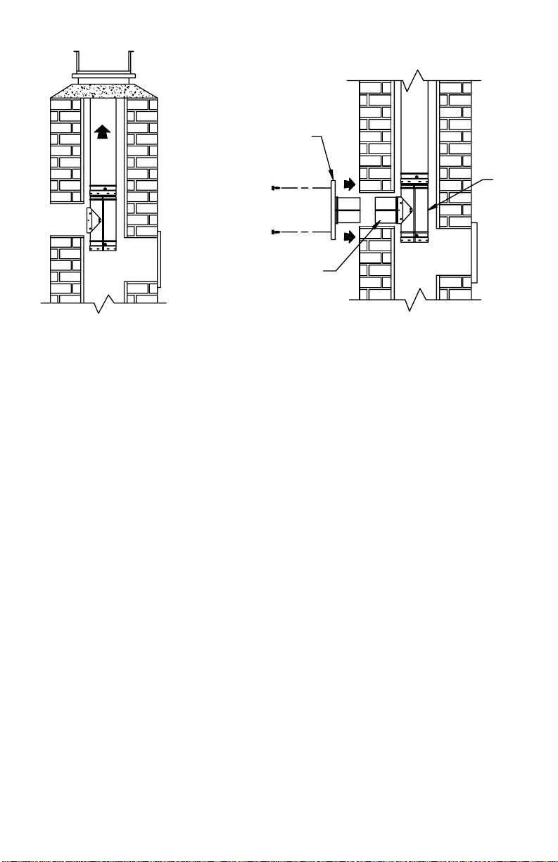
first rigid section of DuraLiner on top of Tee with four stainless steel rivets.
(See Figure 21) After pipe and Tee are riveted together, lower them down
through the Frame of DuraLiner Top and hold in position. Each DuraLiner
pipe section is then riveted and lowered down the chimney. This procedure is
repeated until the Tee reaches the masonry opening.
STEPTHREE: Before you rivet the last section of pipe in place, attach the
Hanger to the pipe just below the top on the last of the rigid DuraLiner pipe.
(SeeFigure 8)As the DuraLinerrigid pipe is beinglowered into final position,
line up the branch of the Tee with hole in the masonry chimney wall. (See
Figure 22).
When branch of tee is in line with hole in wall of masonry chimney, attach
slipconnector fromthe MasonryThimble. The SlipConnectorhas pre-formed
buttons. The buttons snap into branch ring. Slide Thimble section into slip
connector and attach black finishing ring to wall of chimney using screws.
(See Figure 23).
Fig. 22
FRAME
Fig. 23
SEALANT
ANCHOR
SCREWS
SLIPCONNECTOR
FROM MASONRY
THIMBLE
TEE
TEE
MASONRY
THIMBLE
ACCESS
DOOR FOR
CLEANOUT
ACCESS
DOOR FOR
CLEANOUT
NorthlineExpress.com
http://www.northlineexpress.com
Toll-Free 1-866-667-8454
13
EXTEND-A-CAP INSTALLATION
The Extended-A-Cap is used with a DuraLiner
system when it is desired to extend the length
above the level of the existing masonry for the
purpose of improving draft, to accommodate
remodeling, to comply with safety requirements
for height of chimney above the roof, or as an
alternative to the Standard Termination.
Refer to the General Installation Instructions for
the majority of the installation. Extend-A-Cap
installationonly refers tothe top ofthe DuraLiner
installation, and is used instead of the Standard
Termination. All notes, warnings, maintenance
procedures, clearance, and basic instructions
containedinthe General Installation Instructions
are applicable to the Extend-A-Cap.
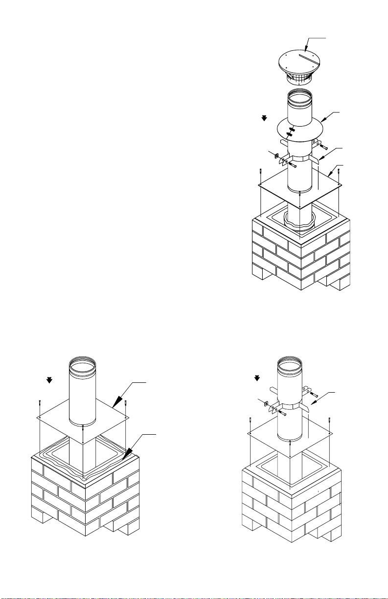
An exploded diagram of the Extend-A-Cap is
shown in Fig. 24. The cap may be installed on both round and oval rigid
systems.
BASE
CLAMP
STORM
COLLAR
CAPAND
SPARK
ARRESTOR
Fig. 24
Fig. 25
SEALANT
BASE
Fig. 26
CLAMP
NorthlineExpress.com
http://www.northlineexpress.com
Toll-Free 1-866-667-8454
14
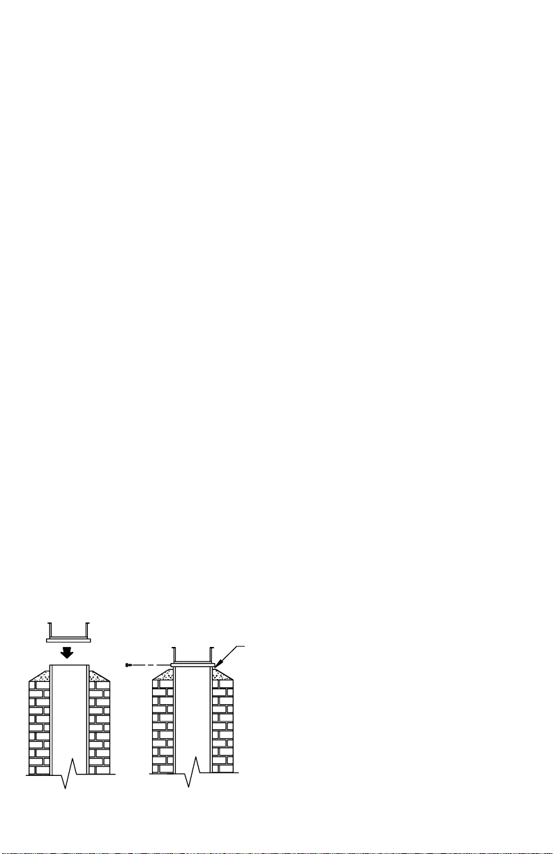
STEP ONE: Center the base plate on the
top of the masonry chimney as shown in
Fig.25. Trimtofitthe chimneyasrequired.
Use non-hardening sealant to seal the base
plate to the masonry chimney, but this can
be done after the liner has been lowered
into place. Anchors or screws are
recommended but not required, as the base
plate will ultimately be supporting the
entire weight of the installation.
STEPTWO: Position the clamp assembly
on top of the base as shown in Figure 26.
Adjust the bolts on the clamp assembly so
that pipe sections will just pass through the
clamp.
STEPTHREE: If needed, remove the existing damper from the fireplace,
as stated in STEP ONE on page 5 of the General Installation Instructions. It
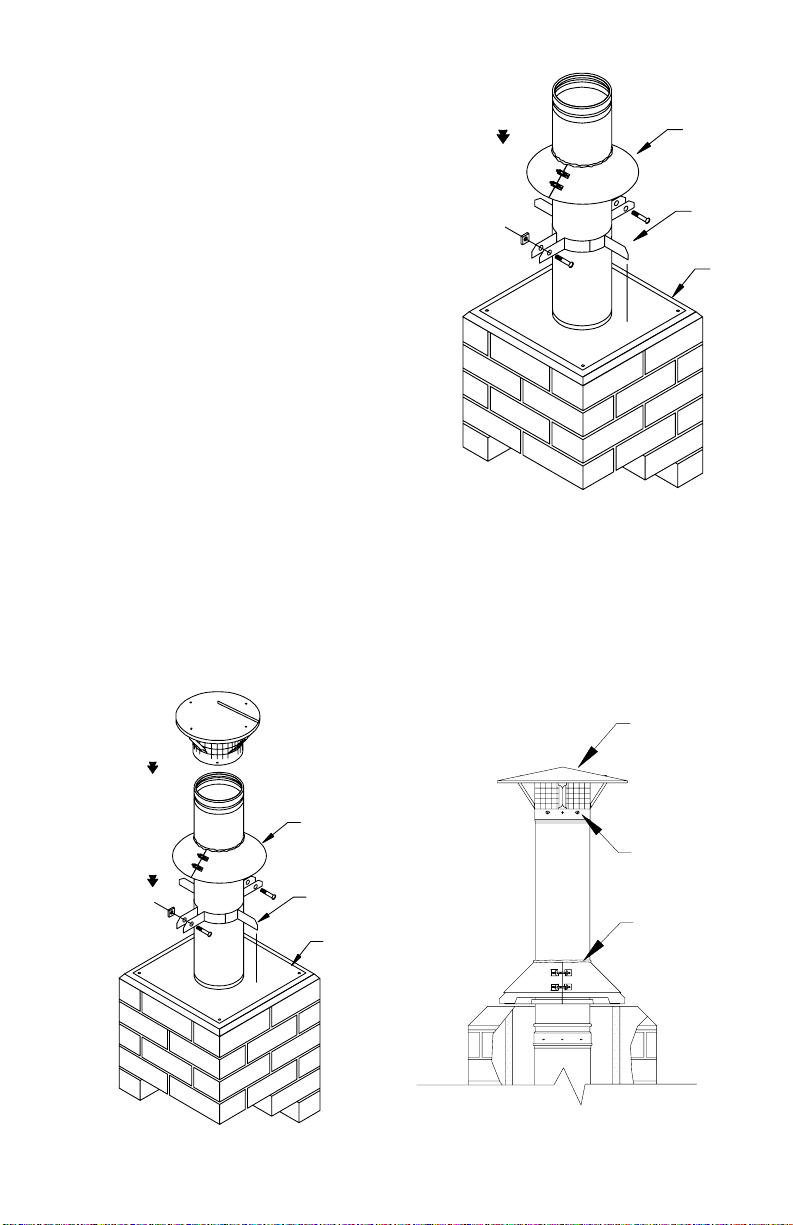
Fig. 27
BASE
CLAMP
STORM
COLLAR
BASE
CLAMP
STORM
COLLAR
Fig. 28
CAP WITH
SPARKARRESTOR
#8 SHEET
METALSCREWS
EXPLODED VIEW COMPLETED EXTEND-A-CAP
BEAD OF SEALANT
AROUND TOP OF
STORM COLLAR
NorthlineExpress.com
http://www.northlineexpress.com
Toll-Free 1-866-667-8454
15
may be necessary to remove part of
the smoke shelf to allow the liner
sections to pass through the throat.
STEP FOUR: After the basic
measurements have been taken, and
the correct parts are on hand, begin
assembling the pipe sections as
described in STEPTHREE on page 6
of the General Installation
Instructions. Alternately tighten and
loosenthe clampassembly tohold and
lower the pipe sections as they are
assembled with pop rivets.
STEPFIVE: Once the desired length of liner has been achieved, tighten the
clampassembly bolts, until thesystemis firmly supported bythe base. Attach
the storm collar, and seal with non-hardening sealant as shown in Figure 28.
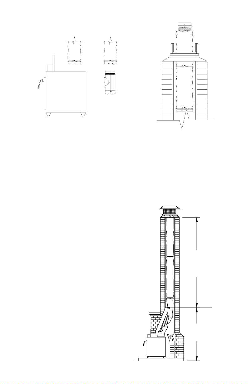
STEPSIX: Install the cap, using #8 sheet metal screws, as shown in Fig. 28.
If the cap is 4-feet or more above the top of the masonry chimney, use an
extended roof bracket as shown in Fig. 29.
STEPSEVEN: Completethe connection of your stove orinsertas described
in STEP FIVE on pages 8, 9, and 10 of the General Installation Instructions.
The Maintenance Instructions contained on page 18 of these Installation
Instructions are all applicable to the Extend-A-Cap installation, other than
cap removal, which is accomplished by removing the four sheet metal screws
holding the band to the pipe section.
DuraLiner systems are designed solely for relining masonry chimneys,
therefore no clearances to combustibles have been established for these
systemsoutside of masonry chimneys. Inview of this,do not construct chases
or other enclosures around DuraLiner pipe sections which extend above the
masonry.
Fig. 29
MORETHAN
4-FEET
EXTENDED
ROOF
BRACKET
NorthlineExpress.com
http://www.northlineexpress.com
Toll-Free 1-866-667-8454
16
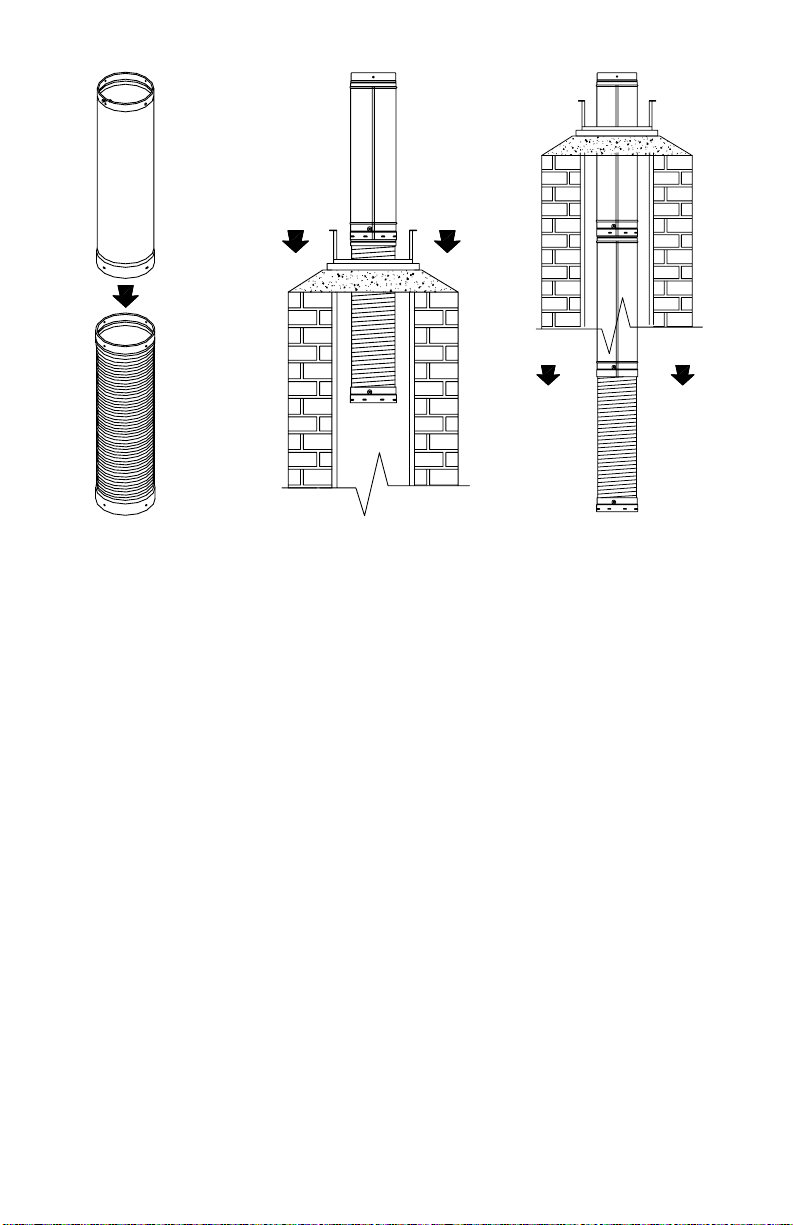
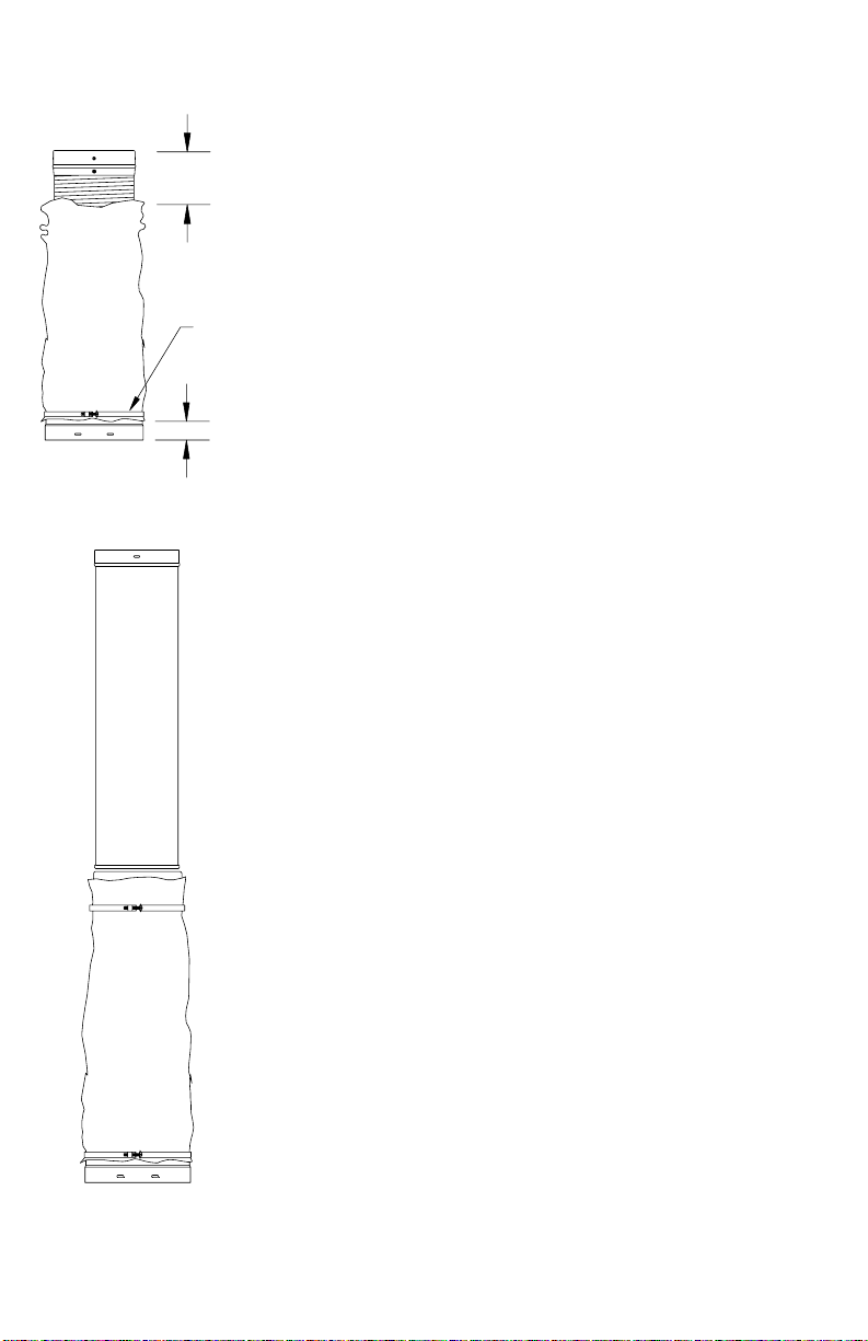
INSTALLING INSULATION SLEEVES
In a situation where the chimney liner consists of rigid
sections,except forthefirst sectionof flexpipe, as shown
in Figure 6 on page 7, and it is desired to insulate the
flex pipe, follow the steps listed below:
STEP ONE: Slip the proper size of the Two-Ply
Insulation Sleeve over the flex pipe, and position it
approximately 1" up from the bottom. (See Figure 30)
Install the bottom insulation sleeve clamp, and push the
top of the sleeve down 4" to 6". Position clamps so that
the nut and bolt connections are pointing towards the
corner of a rectangular chimney.
STEPTWO: Connect the first rigid section of pipe to
the top of the flex pipe using stainless steel pop rivets,
asdescribed intheGeneral InstallationInstructions. (See
Figure 6)
STEPTHREE: Push the insulation sleeve back to its
full length and secure it with an insulation sleeve clamp.
(See Figure 31)
STEP FOUR: From this point on, follow the general
instructions as written. Refer to Figure 6, 7a, 7b, 8, 9
and 10. The liner should now be ready to be attached to
the appliance. (Figure 32).
STEP FIVE: Secure the flex pipe to the insert or tee as
shown in Figure 13 or Figure 14 of the General
Installation Instructions.
STEPSIX: After attaching the insert or the tee, proceed
with the remainder of the General Installation
Instructions.
Fig. 30
Fig. 31
1-INCH
CLAMP
4-6 INCHES
NorthlineExpress.com
http://www.northlineexpress.com
Toll-Free 1-866-667-8454
17
In situations where the chimney liner will consist totally of flex-pipe, insulate
the entire length and follow the steps listed below:
STEPONE: Slip the appropriate sized insulationsleeve over the firstsection
of flex-pipe and position as shown in Figure 30. Lower the first section
down the chimney approximately ¾ of its length, and hold in place.
STEPTWO: Connect the second section
of flex-pipe to the first section by means
of stainless steel pop rivets as described
in the general installation instructions.
STEP THREE: Slip another length of
insulation sleeve over the second section
of flex-pipe. Pull up the top of the lower
section of insulation shield so it overlaps
the top section by 1" to 2" and attach an
insulationsleeve clampas shownin Figure
33.
STEPFOUR: Lower the assembly down
the chimney. Repeat steps and three until
the desired length is achieved.
Fig. 32 Fig. 33
- OR -
TEE
INSERT
Fig. 34
ZERO CLEARANCE TO
MASONRYIN THIS
AREA IF INSULATION
SLEEVE IS USED.
FLUE TILE
STARTSAT
THIS POINT
ZERO CLEARANCE
TO MASONRY IN
THISAREA
NorthlineExpress.com
http://www.northlineexpress.com
Toll-Free 1-866-667-8454

18
STEPFIVE: Complete theinstallation asdescribed inthe GeneralInstallation
Instructions. Complete insulated system shown in Figure 34.
DURALINER MAINTENANCE INSTRUCTIONS
Creosote and Soot-Formation and Need for Removal:
When wood is burned slowly, it produces tar and other organic vapors, which
combine with expelled moisture to form creosote. The creosote vapors may
condenseon theinside ofthe chimneylinerduring slow-burningfiring periods.
Asaresult, creosote residue accumulatesonthe chimney liner. When ignited,
this creosote makes an extremely hot fire.
1. Access – Chimney liners must be installed so that access is provided for
inspection and cleaning.
2. When to Clean – The chimney liner should be inspected at least once
every two months during the heating season to determine if creosote or soot
buildup has occurred. Check spark arrestor screens every 2-4 weeks. If
creosote or soot has accumulated, it should be removed to reduce the risk of
chimney fire. At a minimum, the liner must be cleaned at least once a year.
3.How to Clean –Have your chimney linercleaned by aprofessionalcertified
chimneysweepif you have doubtsabout your ability to cleanit. Use a plastic,
wood, or flexible steel or wire brush. Do not use a brush that will mar the
stainless steel liner surface. Scrub the spark arrestor with a wire brush.
To remove the chimney cap for cleaning, unscrew the four screws that attach
the cap’s support legs to the cap base.
4. Coal – To reduce corrosion in chimneys where coal is burned, clean the
chimneythoroughly within 48hours of shuttingdownthe stoveforthe season.
Check the chimney’s lining for acid corrosion regularly.
5. No Chemical Cleaners – Do not use chemical chimney cleaners. Their use
does not eliminate the need for mechanical cleaning and they may be highly
corrosive.
NorthlineExpress.com
http://www.northlineexpress.com
Toll-Free 1-866-667-8454

19
6. In case of Fire – If a flue fire occurs, close all appliance draft openings and
call your Fire Department. Do not use the chimney again until it is inspected
for possible damage.
7.Flues – Connect onlyone solid fuel applianceperchimney liner. DuraLiner
shall be sized not less than that specified in the appliance manufacturer’s
instructions.
8.Appliance – Choose an appliance that is listed by a recognized testing and
listing agency and is not larger than you need.
NorthlineExpress.com
http://www.northlineexpress.com
Toll-Free 1-866-667-8454

20
SIMPSON DURA-VENT, INC.
ENGINEERED EXCELLENCE
45 YEARS OF LEADERSHIP IN CHIMNEY DESIGN.
SIMPSON DURA-VENT, P.O. BOX 1510,
VACAVILLE, CA 95696-1510
VICKSBURG, MS
(800) 835-4429 (707) 446-4740 FAX
www.duravent.com June 2005
L402
WARRANTY
Simpson Dura-Vent warrants DuraLiner for a period of 25 years from date of
installation. The warranty includes all components and fittings except
chimney caps. Chimney caps carry a five-year warranty. All warranties,
whether expressed or implied, shall be limited to replacement (exclusive of
installation costs) of the product found to be defective under this warranty
providing all recommended installation and maintenance instructions are
followed.
NorthlineExpress.com
http://www.northlineexpress.com
Toll-Free 1-866-667-8454
Table of contents


