Nortrac 40XTD User manual

40XTD Bulldozer
Owner’s Manual
WARNING: Read carefully and understand all ASSEMBLY AND OPERATION
INSTRUCTIONS before operating. Failure to follow the safety rules and other basic safety
precautions may result in serious personal injury.
Item #819299

Page 2/ 48
Thank you very much for choosing a NorTrac™product!
For future reference, please complete the owner’s record below:
Serial Number/Lot Date Code: ________________________________
Purchase Date: ____________________________________________
Save the receipt, warranty, and this manual. It is important that you read
the entire manual to become familiar with this product before you begin
using it.
This bulldozer is designed for certain applications only. Northern Tool
and Equipment is not responsible for issues arising from modification or
improper use of this product such as an application for which it was not
designed. We strongly recommend that this product not be modified
and/or used for any application other than that for which it was designed.
For technical questions, please call 1-800-521-0438.

Page 3/ 48
Table of Contents
Intended Use....................................................................................................................................4
Packaging Contents ........................................................................................................................4
Technical Specifications.................................................................................................................4
Important Safety Information ..........................................................................................................6
Specific Operation Warnings..........................................................................................................8
Grounding......................................................................................................................................10
Safety and Product Labels............................................................................................................10
Before Each Use............................................................................................................................14
Operating Instructions ..................................................................................................................16
After Each Use...............................................................................................................................33
Maintenance...................................................................................................................................33
Troubleshooting ............................................................................................................................39
Parts Diagram................................................................................................................................44
Parts List........................................................................................................................................44
Replacement Parts ........................................................................................................................45
Limited Warranty ...........................................................................................................................46

Page 4/ 48
Intended Use
The NorTrac 40XTD Bulldozer is incredibly strong and versatile, perfect for tough earth moving, ground
leveling, road carving, and deforestation jobs for estate owners, landscape contractors, and builders. The 3-
cylinder, diesel engine provides enough power to move tons of dirt, gravel, and other materials around your
jobsite. The manual 8-forward and 2-reverse speed transmission provides the right gear for any situation.
Engine performance is monitored by the fuel, oil pressure, and temperature gauges, as well as the amp meter
and tachometer. With a category 1 rear hitch, the bulldozer can be used with implements such as a backhoe,
post hole digger, cultivator, and more. Includes a heavy-duty seat and easy-to-use controls.
Packaging Contents
•40XTD Bulldozer
•Bulldozer Owner’s Manual
•Bulldozer Parts List
•Tool Set
•Spare Part Set
•Bulldozer Packing List
Technical Specifications
Dozer Dimensions
Specification
Overall length, with blade or loader (mm)
2960
Overall length, no blade or loader (mm)
2260
Overall width, with straight blade or loader (mm)
1650
Overall width, no blade or loader (mm)
1440
Overall height to top of ROPS (mm)
2270
Ground contact length (mm)
1400
Track gauge (mm)
1150
Shoe width (mm)
290
Ground clearance (mm)
240
Operating weight (lb.)
6569.78
Max. drawbar pull (lb.)
5423.37
Six-Action Blade
Height of blade (mm)
675
Lift height of blade (mm)
500
Max. digging depth of blade (mm)
80
Blade capacity (m3)
0.67

Page 5/ 48
Performance
Part
Property
Specification
Engine
Model
403F-E17T (Perkins)
Type
3-cylinder, turbo-charged
Cylinder bore
84 mm
Piston stroke
100 mm
Displacement
1.7 L
Max. power
29 kw @ 2800 RPM
Max. torque
120 Nm @ 1800 RPM ± 5%
Fuel
Diesel
Idling
800 r/min
Direction of rotation
Counter-clockwise
Post-processing system
DOC
Emission certificate
EPA tier 4 final
Model
403F-E17T (Perkins)
Transmission
Clutch
Single dry disk diaphragm spring clutch
10”, pedal control
Gearbox
2-shaft, sliding gear shift, 8 fwd+2 rev
Main drive
Spiral bevel gear
Final drive
Externally meshed spur gear
Brake & Steering
(interconnected)
Steering clutch
Dry, ceramic-metallic, multi-disk clutch
Brakes
Brand brakes controlled by pedals
Under Carriage
System
Under carriage frame
Semi-rigid
Track roller (each side)
5+1
Tension device
Helical spring, adjusted by screw
Number of shoes
39 (1pitch=109mm)
Hydraulic Blade and
3-point Hitch
System
Gear pump
Spline Clockwise 26/32DP
Rated capacity
29.4 LPM (7.7 GPM)
(depending on rotation speed of engine)
Rated pressure of relief valve
16MPa (2230 PSI)
Control valve
6-spool
Blade control
Lift: raise, hold, lower, float
Angle: right, hold, left
Tilt: right, hold, left
Blade lift cylinder bore X
stroke/number
Double action 50mm X285mm / 2
Blade angle cylinder bore
X stroke/number
Double action 63mm X280mm / 2
Blade tilt cylinder bore
X stroke/number
Double action 63mm X50mm / 1
Hitch control –1 level
Raise, hold, lower (float)
Cylinder bore X
stroke/number
63mm X 90mm / 1
Lift capacity @ hitch point
7350 N (1650 lb.)
Lifting height @ hitch point
720 mm
Type of hitch
Rear 3-point, category I
Electrical System
Voltage
12V
Alternator
12V 85A
Starter
12V/2 KW
Battery (free maintenance)
90 Ah
Front headlamp/number
30 w/ 2
Roof front/rear led
light/number
30 w/ 4
Power Take-off
Type
Mechanical, dependent

Page 6/ 48
Part
Property
Specification
Two rotary speeds
540 RPM @ engine 1812 RPM
1000 RPM @ engine 1772 RPM
Shaft diameter
35mm (13/8”), 6 splines
Service Capacity
Fuel
28 l (7.4 gal)
Engine oil sump
5.5 l (1.6 gal)
Gearbox
11 l (2.9 gal)
Hydraulic system
26 l (6.8 gal)
Coolant
9 l (2.3 gal)
Final drives (each)
2 l (0.5 gal)
Important Safety Information
⚠WARNING
Read and understand all instructions. Failure to follow all instructions may result in serious injury or
property damage.
The warnings, cautions, and instructions inthis manualcannot cover all possible conditions or situations
that could occur. Exercise common sense and caution when using this tool. Always be aware of the
environment and ensurethat the tool is used in a safe and responsible manner.
Do not allow persons to operate or assemble the product until they have read this manual and have
developed a thorough understanding of how it works.
Do not modify this product in any way. Unauthorized modification may impair the function and/or safety
andcould affect the lifeof theproduct.Therearespecificapplicationsfor whichthe product wasdesigned.
Use the right tool for the job. DO NOT attempt to force small equipment to do the work of larger industrial
equipment. There are certain applications for which this equipment was designed. This product will be
safer and do a better job at the capacity for which it was intended. DO NOT use this equipment for a
purpose for which it was not intended.
Industrial or commercial applications must follow OSHA requirements.
⚠WARNING
PROP 65
Breathing diesel engine exhaust exposes you to chemicals known to the State of California to cause cancer
and birth defects or other reproductive harm.
•Always start and operate the engine in a well-ventilated area.
•If in an enclosed area, vent the exhaust to the outside.
•Do not modify or tamper with the exhaust system.
•Do not idle the engine except as necessary.

Page 7/ 48
⚠WARNING
WORK AREA SAFETY
Inspect the work area before each use. Keep work area clean, dry, free of clutter, and well-lit. Cluttered,
wet, or dark work areas can result in injury. Using the product in confined work areas may put you
dangerously close to cutting tools and rotating parts.
Do not use the product where there is a risk of causing a fire or an explosion; e.g., in the presence of
flammable liquids, gases, or dust. The product can create sparks, which may ignite the flammable liquids,
gases, or dust.
Do not allow the product to come into contact with an electrical source. The tool is not insulated and
contact will cause electrical shock.
Keep children and bystanders away from the work area while operating the tool. Do not allow children to
handle the product.
Be aware of all power lines, electrical circuits, water pipes, and other mechanical hazards in your work
area. Some of these hazards may be hidden from your view and may cause personal injury and/or
property damage if contacted.
⚠WARNING
PERSONAL SAFETY
Stay alert, watch what you are doing, and use common sense when operating the tool. Do not use the
tool while you are tired or under the influence of drugs, alcohol, or medication. A moment of inattention
while operating the tool may result in serious personal injury.
Dress properly. Do not wear loose clothing, dangling objects, or jewelry. Keep your hair, clothing and
gloves away from moving parts. Loose clothes, jewelry, or long hair can be caught in moving parts. Air
vents on the tool often cover moving parts and should be avoided.
Wear the proper personal protective equipment when necessary. Use ANSI Z87.1 compliant safety
goggles (not safety glasses) with side shields, or whenneeded, a face shield. Use a dust mask in dusty
work conditions. Also use non-skid safety shoes, hardhat, gloves, dust collection systems, and hearing
protection when appropriate. This applies to all persons in the work area.
Do not overreach. Keep proper footing and balance at all times.
Remove keys or wrenches before connecting the tool to an air supply, power supply, or turning on the
tool. A wrench or key that is left attached to a rotating part of the tool may cause personal injury.
Secure the work with clamps or a vise instead of your hand when practical. This safety precaution
allows for proper tool operation using both hands.
⚠CAUTION
BULLDOZER USE AND CARE
Do not force the bulldozer. Products are safer and do a better job when used in the manner for which
they are designed. Plan your work and use the correct product for the job.
Check for damaged parts before each use. Carefully check that the product will operate properly and

Page 8/ 48
perform its intended function. Replace damaged or worn parts immediately. Never operate the product
with a damaged part.
Do not use a product with a malfunctioning switch. Any power tool that cannot be controlled with the
power switch is dangerous and must be repaired by an authorized service representative before using.
Disconnect the power/air supply from the product and place the switch inthe locked or off position before
making any adjustments, changing accessories, or storing the tool. Such preventive safety measures
reduce the risk of starting thetool accidentally.
Store the product when it is not in use. Store it in a dry, secure place out of the reach of children. Inspect
the tool for good working condition prior to storage and before re-use.
Use only accessories that are recommended by the manufacturer for use with your product. Accessories
that may be suitable for one product may create a risk of injury when used with another tool. Never use
an accessory that has a lower operating speed or operating pressure than the tool itself.
Keep guards in place and in working order. Never operate the product without the guards in place.
Do not leave the tool running unattended.
Specific Operation Warnings
⚠WARNING
•To prevent serious injury or property damage, read and understand owner’s manual before operating.
•Always wear the proper protective equipment including ANSI Z87.1 compliant eye protection, hearing
protection, steel toed boots, heavy-duty work gloves, and hard hat.
•Keep hands clear of all rotating parts and hot surfaces.
•Follow all start up procedures before each use.
•Before each use, inspect track tension and adjust if needed.
•To prevent personal injury or property damage, retighten the nuts on driven wheel per working 50 hours.
Torque is 160-180 Nm.
•When operating on slopes, do not make sharp turns.
•Operate all controls from the operator’s position.
•Keep all safety shields and enclosures in place when operating this equipment.
•Do not operate around children.
•Vehicle is frequently reversing. Keep workers and bystanders clear from behind the dozer while
operating.
•Keep all bystanders at least 20 feet away from work area.
•EXPOLSION HAZARD. Lead acid batteries create hydrogen gas. No smoking, sparks, or open flames
•HIGH-PRESSURE FLUID HAZARD
•Inspect hydraulic system regularly for leaks.
•Hydraulic fluid escaping through even a pin-size hole opening can puncture skin and cause blood
poisoning.

Page 9/ 48
•Wear proper hand and eye protection when searching for leaks. Never check for leaks with your
hand while system is pressurized. Use wood or cardboard instead of hands
•Relieve pressure on hydraulic system before servicing or disconnecting hoses.
•Seek medical attention immediately if injured by escaping fluid.
•FIRE HAZARD
•Do not fuel at the worksite
•Refuel machine on a hard, level surface.
•Keep open flames and sparks away from the machine while fueling.
•Do not smoke while fueling.
•Do not fill beyond the overfill marking. Expansion of fuel from heat of sun or normal operation may
cause tank spillage if overfilled.
•Clean up any fuel spills before starting engine.
•ENTANGLMENT HAZARD. To prevent serious injury or death from rotating driveline:
•Keep hands, feet, clothing, and hair away from rotating driveline.
•Do not operate without all driveline, tractor, and equipment shields in place.
•Do not operate without driveline securely attached at both ends.
•Do not operate without driveline shields that turn freely on driveline.
•CRUSH AND DISMEMBERMENT HAZARD. Keep hands and feet away from track when engine is on.
Shut engine off before servicing track.
•ELECTROCUTION HAZARD. Serious injury or death can result from contact with electric lines.
•Check overhead clearance before driving under electric lines.
•Check with utility company for underground utilities before excavating.
•FALL HAZARD. On entry and exit of the dozer:
•Maintain 3 points of contact at all times.
•Climb up forwards, exit backwards
•Never jump down from this machine
•Ensure the steps are clean
•Do not climb in or out of the dozer while in motion.
•FALL HAZARD
•Maximum of one person per seat.
•Do allow riders on machine or its attachments.
•Wear seatbelt at all times.
•To avoid property damage, remove backhoe if not in use while operating machine.
•Follow all shutdown procedures and read manual before servicing.

Page 10 / 48
Grounding
⚠WARNING
The coolant heater must be grounded while in use to protect the operator from electrical shock. The
plug MUST be plugged into a matching receptacle that is properly installed and grounded in
accordance with ALL local codes and ordinances.
DO NOT MODIFY THE PROVIDED PLUG. If it will not fit the receptacle, have the proper receptacle
installed by a qualified electrician.
CHECK with a qualified electrician or service person if you do not completely understand the grounding
instructions, or if you are not sure the tool is properly grounded.
Grounded Tools: Tools with 3-Prong Plugs
The coolant is equipped with a heater which has a 3-prong plug. This needs to be grounded when plugged in to
a 110-volt wall socket.
Safety and Product Labels
Ref.#
Description
Quantity
1
NorTrac Decal
2
2
Vehicle Reversing Warning Decal
1
3
Crush Hazard (Hand) Warning Decal
2
4
Crush Hazard (Body) Warning Decal
2
5
Fall Hazard Warning Decal
2
6
Entanglement Hazard Danger Decal
1
7
#1 Track Maintenance Warning Decal
2
8
Burn Hazard Warning Decal
1
9
#1 High-Pressure Fluid Hazard Warning Decal
2
10
Rotating Blade Hazard Warning Decal
1
11
Explosion Hazard Warning Decal
1

Page 11 / 48
Ref.#
Description
Quantity
12
Burn Hazard (Hot Coolant) Warning Decal
1
13
#2 High-Pressure Fluid Hazard Warning Decal
1
14
Hydraulic Filter Notice Decal
1
15
ROPS Warning Decal
2
16
Fire Hazard Danger Decal
1
17
#2 Track Maintenance Warning Decal
2
18
Start Up/Shut Down Procedure, Operational Warnings, Prop 65 Warning Decals
1
19
Electrocution Hazard Danger Decal, Fall Hazard Warning Decals, Engine Notice Decal
1
20
Diesel Fuel Decal
1
21
Diesel Fuel Drain Decal
1
22
Parking Brake Decal
1
23
Hood Instruction Decal
1
24
Hydraulic Oil Level Decal
1
25
Hydraulic Oil Drain Decal
1
26
Blade Control, Hitch Control, Rear Hydraulic Oil Control Valve Decal
1
27
Power Take Off Decal
1
28
#1 Work Lights Decal
1
29
#2 Work Lights Decal
1
30
Dashboard Decal
1
1.
2.
3.
4.
5.
6.

Page 12 / 48
7.
8.
9.
10.
11.
12.
13.
14.
15.
16.
17.

Page 13 / 48
18.
19.
20.
21.
22.
23.
24.
25.

Page 14 / 48
26.
27.
28.
29.
30.
Before Each Use
⚠WARNING
•Always wear the proper protective equipment including ANSI Z87.1 compliant eye protection, hearing
protection, steel toed boots, heavy-duty work gloves, and hard hat.
•Follow all start up procedures before each use.
•Before startup, check all fluids including engine oil, hydraulic oil, and coolant.
•Before each use, inspect track tension and adjust if needed.
•Keep all bystanders at least 20 feet away from work area.
•To avoid property damage, remove backhoe if not in use while operating machine.
Precautions Before Run-in
1. Clean the area around the dozer.
2. Check and retighten all outer connections, such as bolts and nuts.
3. Check and fill the lubricant, water, fuel, and hydraulic oil to sufficient levels.

Page 15 / 48
Dozer Run-in
10 Minutes Run-in of the Engine at Idle Speed
Start up the engine and increase the engine speed to raise coolant temperature and the engine oil pressure.
Check if there is any oil or water leaking. Pay attention to the sound of the engine running and notice the
indication of the ammeter, water thermometer, and the oil pressure gauge. Continue the next run-in
procedure only after this 10 min run-in.
10 Minutes Run-in of Hydraulic Hitch System
After an implement has been mounted, the hitch is raised and lowered smoothly for more than 10 min, when
the engine is running at rated speed in order to keep run-in smooth, the implement cannot be raised or
lowered on the hard ground.
Two-hour Run-in Without Load
The dozer should be in run-in according to normal use and the operator should do the following.
Shifts
F-low 1
F-low 2
F-low 3
f-high 1
R 1
Time (min)
20
30
30
30
10
In this run-in, the operation of both sides of the steering system and the brake should be carried out. It’ s
necessary to pay attention to the following items.
•Listen to the engine and transmission.
•Check whether the clutch, brake, and gearshift levers are normal.
•Check whether the gauges and electrical system work normally.
If abnormal occurs during the run-in, address it before continuing the run-in process.
48-hour Run-in Under Load Conditions
‘Run-in with load’means that it’s necessary to run the dozer with different loads. The load should be
increased gradually from light to heavy while increasing the speed from low to high.
Measures After Run-in
After the run-in, if any impurities are found in the engine oil sump, gearbox, or hydraulic system, it must be
removed. Also, replace all lubricants and the hydraulic oil. After the essential maintenance, the dozer can be
put into normal use The maintenance steps are as follows:
•Drain out the engine oil when it’s hot, just after the engine is shut off. Then clean the sump with clean
diesel fuel and replace the engine oil filter element. Lastly, refill the engine oil.
•Drain out the oil from the gearbox and final drive cases when it’s hot, just after the engine is shut off.
Then, refill with clean diesel fuel and run the dozer for 3-5 minutes at lowest speed. Drain diesel and fill
with the appropriate amount of clean oil.
•Replace the fuel filter element.
•Drain out the oil from the hydraulic system and refill with the appropriate amount of clean hydraulic oil.
•Replace engine’s coolant.
•Fill grease into the lubricating points in accordance with indication of lubricating drawing.
•Check the tension of the tracks. If the sag exceeds 2.5mm (1in.), adjust.
•Inspect the brake and steering pedals’ free strokes, adjust if necessary.
•Inspect all fasteners and retighten any loose connections.

Page 16 / 48
Operating Instructions
⚠WARNING
•Always wear the proper protective equipment including ANSI Z87.1 compliant eye protection, hearing
protection, steel toed boots, heavy-duty work gloves, and hard hat.
•Keep hands clear of all rotating parts and hot surfaces.
•To prevent personal injury or property damage, retighten the nuts on driven wheel per working 50 hours.
Torque is 160-180 Nm.
•When operating on slopes, do not make sharp turns.
•Operate all controls from the operator’s position.
•Keep all safety shields and enclosures in place when operating this equipment.
•Do not operate around children.
•Vehicle is frequently reversing. Keep workers and bystanders clear from behind the dozer while
operating.
•Keep all bystanders at least 20 feet away from work area.
•EXPOLSION HAZARD. Lead acid batteries create hydrogen gas. No smoking, sparks, or open flames
•HIGH-PRESSURE FLUID HAZARD
•Inspect hydraulic system regularly for leaks.
•Hydraulic fluid escaping through even a pin-size hole opening can puncture skin and cause blood
poisoning.
•Wear proper hand and eye protection when searching for leaks. Never check for leaks with your
hand while system is pressurized. Use wood or cardboard instead of hands.
•Relieve pressure on hydraulic system before servicing or disconnecting hoses.
•Seek medical attention immediately if injured by escaping fluid.
•FIRE HAZARD
•Do not fuel at the worksite.
•Refuel machine on a hard, level surface.
•Keep open flames and sparks away from the machine while fueling.
•Do not smoke while fueling.
•Do not fill beyond the overfill marking. Expansion of fuel from heat of sun or normal operation may
cause tank spillage if overfilled.
•Clean up any fuel spills before starting engine.
•ENTANGLMENT HAZARD. To prevent serious injury or death from rotating driveline:
•Keep hands, feet, clothing, and hair away from rotating driveline.
•Do not operate without all driveline, tractor, and equipment shields in place.
•Do not operate without driveline securely attached at both ends.
Page 17 / 48
•Do not operate without driveline shields that turn freely on driveline.
•CRUSH AND DISMEMBERMENT HAZARD. Keep hands and feet away from track when engine is on.
Shut engine off before servicing track.
•ELECTROCUTION HAZARD. Serious injury or death can result from contact with electric lines.
•Check overhead clearance before driving under electric lines.
•Check with utility company for underground utilities before excavating.
•FALL HAZARD. On entry and exit of the dozer:
•Maintain 3 points of contact at all times.
•Climb up forwards, exit backwards.
•Never jump down from this machine.
•Ensure the steps are clean.
•Do not climb in or out of the dozer while in motion.
•FALL HAZARD
•Maximum of one person per seat.
•Do allow riders on machine or its attachments.
•Wear seatbelt at all times.
•To avoid property damage, remove backhoe if not in use while operating machine.
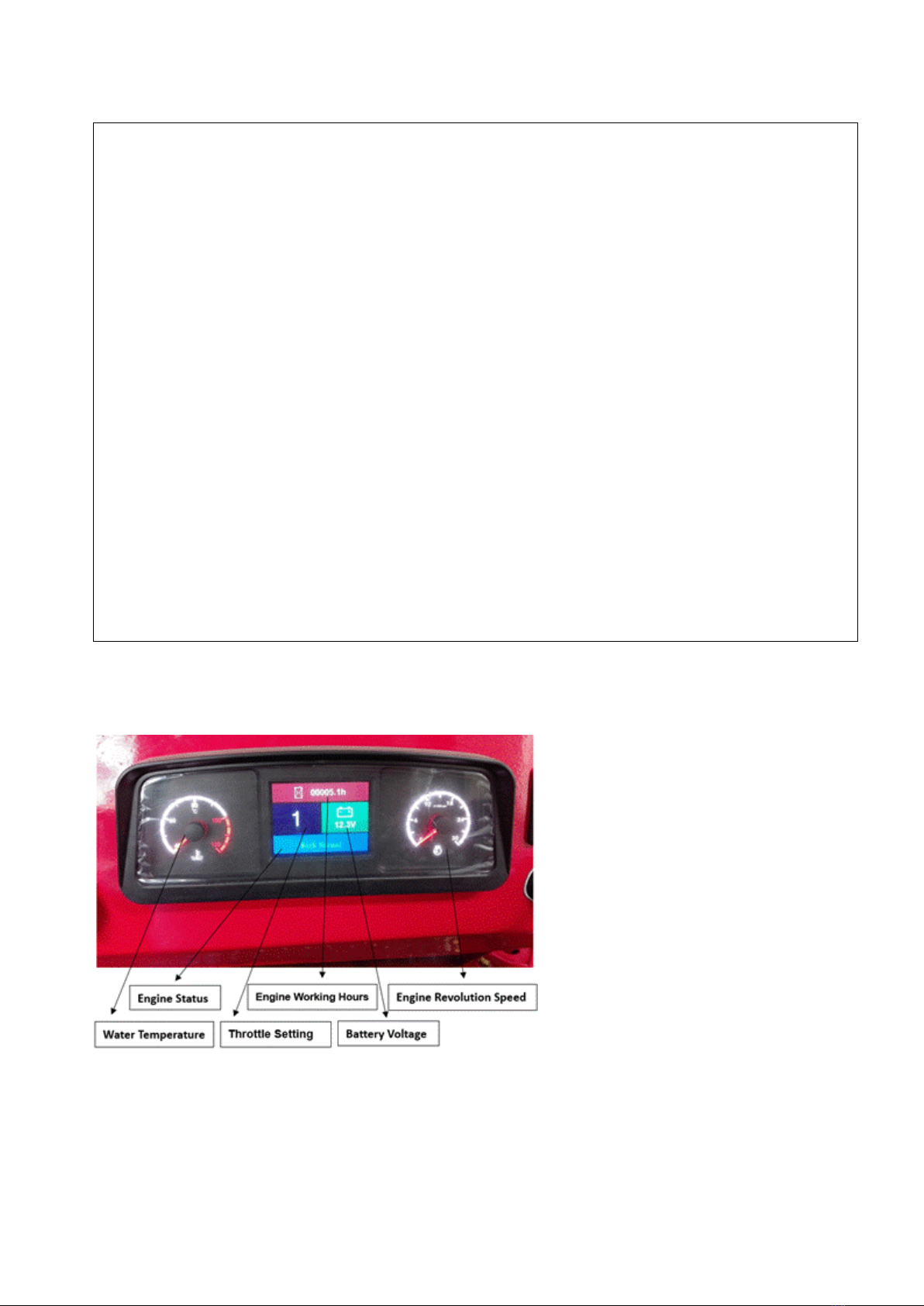
Controls, Gauges, and Switches on Dash Board

Page 18 / 48
Warm-up and Start-up Switch: Choke Control
•When the key is in the OFF position, all circuits are off.
•Turn clockwise to ‘H’ to warm up the engine. Continue to ‘ST’ to start it up (after warm-up).
•When it’s turned clockwise to ON, all circuits, except warm-up and start-up circuit, are on (after start-up,
the key is kept in this position).
Throttle Control
•Turn clockwise to increase throttle (10 grades for accelerating adjustments showing on screen).
•Turn counter-clockwise to decrease throttle.
Lamp Switches (left side of meter)
•The left switch controls the head light on the front hood.
•The right switch controls the roof light on the cab.

Page 19 / 48
Throttle Setting Switch & Lamp Switch (right side of meter)
•The left switch defines the throttle adjustment range before the throttle control adjustment. Press and
hold for 15 seconds to set the throttle.
•The right switch controls the two head lights on the front cab.
PTO Control Handle
•Push the handle forward to increase speed.
•Push the handle backward to decrease speed.
•Put the handle in neutral so the PTO is not engaged. The clutch pedal must be pushed all the way in
before using the handle.
Driving Operation
Engine Start-up Preparations
Check the engine oil level in the sump and the gearbox. It’s very important that you keep the oil levels between
the upper and lower lines. Be sure there is sufficient coolant in the radiator and sufficient fuel in the tank.
PTO control handle at left
side of seat

Page 20 / 48
Check the hydraulic oil level in the tank.
Engine Oil Level in the
Engine
Step 1. Find the oil
dipstick.
Step 2. Pull out the
dipstick to check the oil
lever before starting
engine.
Pull out the transmission
fluid dipstick and check
the transmission fluid at
the floorboard before
starting the engine.
While it’s cold, open the
filler cap on top of the
radiator. Check the
coolant level. It should
be at the top.
Fuel tank gauge
Hydraulic Oil Level Gauge
Located on the right-side of the box.
This manual suits for next models
1
Table of contents
Other Nortrac Tractor manuals


 Operator's manual")


