Nos 05159NOS User manual

2016-2019 Chevrolet Camaro SS Nitrous Kit Number
05159NOS, 05159BNOS, 05166NOS, & 05166BNOS
OWNER’S MANUAL

2
CONGRATULATIONS on purchasing your NOS Nitrous Oxide Injection System! Your system is composed of the highest quality
components available. It should provide many miles of trouble-free performance when used correctly. If you have any questions
regarding the performance of your system, call NOS Technical Service at 1-866-464-6553 or for online help, refer to the Tech
Service section of our website: www.holley.com.
NOTICE: The installation of Nitrous Oxide Systems, Inc. products signifies that you have read this document and have agreed
to the terms stated within.
It is the purchaser’s responsibility to follow all installation instruction guidelines and safety procedures supplied with the product as it is
received by the purchaser to determine the compatibility of the product with the vehicle or the device the purchaser intends to install the
product on.
Nitrous Oxide Systems Inc. assumes no responsibility for damages occurring from accident, misuse, abuse, improper installation,
improper operation, lack of reasonable care, or all previously stated reasons resulting from incompatibility with other manufacturers’
products.
Nitrous Oxide Systems Inc. assumes no responsibility or liability for damages incurred by the use of products manufactured or sold by
Nitrous Oxide Systems Inc. on vehicles used for competition or racing.
Nitrous Oxide Systems Inc. neither recommends nor condones the use of products manufactured or sold by Nitrous Oxide Systems Inc.
on vehicles, which may be driven on public roads or highways, and assumes no responsibility for damages incurred by such use.
NOS nitrous oxide is legal for use in most states when used in accordance with state and local traffic laws. NOS does not recommend
or condone the use of its products in illegal racing activities.
NOS has not pursued California Air Research Board (CARB) exemptions for its kits, hence, they are not legal for use on pollution-
controlled vehicles in California. A correctly installed NOS nitrous system should not alter the emission control performance of your
vehicle under standard EPA test cycle conditions.
HAZARDS DEFINED
This manual presents step-by-step instructions that describe the process of installing your NOS Nitrous Oxide Injection System. These
procedures provide a framework for the installation and operation of this kit. Parts are referenced by name and number to avoid
confusion. Within the instructions, you are advised of potential hazards, pitfalls, and problems to avoid. The following examples
explain the various hazard levels:
WARNING! Failure to comply with instructions may result in injury or death.
CAUTION! Failure to comply with instructions may result in damage to equipment.
NOTE: This information is important, needs to be emphasized, and is set apart from the rest of the text.
HINT: These special instructions provide a handy work tip.
NITROUS OXIDE INJECTION SYSTEM SAFETY TIPS
WARNINGS
IT IS NOT LEGAL TO ENGAGE NITROUS OXIDE INJECTION SYSTEMS ON PUBLIC ROADS OR HIGHWAYS.
NITROUS OXIDE INJECTION SYSTEMS ARE ONLY TO BE ENGAGED DURING SANCTIONED COMPETITION OR
RACING EVENTS.
Do not attempt to start the engine if the nitrous has been injected while the engine was not running. Disable the ignition and
fuel systems (consult owner’s manual) and turn the engine over with the throttle wide open for several revolutions before
attempting to start. Failure to do so can result in extreme engine damage.
Never permit oil, grease, or any other readily combustible substances to come in contact with cylinders, valves, solenoids,
hoses, and fittings. Oil and certain gases (such as oxygen and nitrous oxide) may combine to produce a highly flammable
condition.
Never interchange nitrous and fuel solenoids. Failure to follow these simple instructions can result in extreme engine
damage and/or personal injury.
Never drop or violently strike the bottle. Doing so may result in an explosive bottle failure.

3
Never change pressure settings of safety relief valve on the nitrous bottle valve. Increasing the safety relief valve pressure
settings may create an explosive bottle hazard.
Please note that the NOS bottle label has changed to a two-part assembly. The first label is already located on the bottle.
Upon filling your bottle with nitrous oxide, apply the (second) material information label in the area indicated in the picture to
the right.
NOTE: The material information decal is located in the same
plastic bag as the bottle.
WARNING! Once the nitrous bottle has been filled, it must be
shipped according to the applicable transportation and shipping
regulations!
Do not deface or remove any markings, which are used for
content identification.
Nitrous bottle valves should always be closed when the system
is not being used.
Notify the supplier of any condition that may have permitted any
foreign matter to enter the valve or bottle.
Keep the valves closed on all empty bottles to prevent
accidental contamination.
After storage, open the nitrous bottle valve for an instant to
clear the opening of any possible dust or dirt.
It is important that all threads on the valves and solenoids are properly mated. Never force connections that do not fit
properly.
TABLE OF CONTENTS
WHAT IS NITROUS OXIDE? .......................................................................................................................................4
DO’S AND DON’TS OF NITROUS OXIDE ..................................................................................................................4
Chapter 1 Introduction to Your NOS Nitrous Oxide Kit ..........................................................................................4
1.1 General Information.............................................................................................................................................4
1.2 System Requirements .........................................................................................................................................5
1.3 Kit Components ...................................................................................................................................................5
Chapter 2 Kit Installation............................................................................................................................................7
2.1 Bottle Mounting Instructions ................................................................................................................................7
2.2 Bottle Orientation.................................................................................................................................................7
2.3 Bottle Installation .................................................................................................................................................7
2.4 Solenoid Fittings and Bracket Mounting..............................................................................................................8
2.5 Kit Plate Installation .............................................................................................................................................9
2.6 Fuel and Nitrous Supply Connection .................................................................................................................11
2.7 Electrical System ...............................................................................................................................................13
2.8 Preparing for Operation.....................................................................................................................................16
2.8.1 Programming the Mini 2-Stage Progressive Controller .................................................................................................17
Chapter 3 Tuning.......................................................................................................................................................19
Chapter 4 Determining Optimum System Performance........................................................................................19
Chapter 5 Alternate Sensor, Actuator, and Switch Components.........................................................................20
Chapter 6 Routine Maintenance ..............................................................................................................................21
6.1 Nitrous Solenoid Filter .......................................................................................................................................21
6.2 Nitrous Solenoid Plunger...................................................................................................................................21
6.2.1 General Information.......................................................................................................................................................21
6.2.2 Nitrous Solenoid Plunger Disassembly and Inspection.................................................................................................21
Appendix A Troubleshooting Guide .......................................................................................................................23
Nitrous Oxide Accessories ......................................................................................................................................24
4
WHAT IS NITROUS OXIDE?
NITROUS OXIDE…
…Is a cryogenic gas composed of nitrogen and oxygen molecules
…Is 36% oxygen by weight
…Is non-flammable by itself
…Is stored as a compressed liquid
…Exists in two grades—U.S.P. and Nitrous Plus:
U.S.P. is medical grade nitrous oxide; its common use is dental and veterinary anesthesia. It is also commonly used as a
propellant in canned whipped cream. U.S.P. is not available to the public.
Nitrous Plus differs from U.S.P. in that it contains trace amounts of Sulphur dioxide added to prevent substance abuse. Nitrous
Plus is intended for automotive applications and is available for sale to the public.
In automotive applications, Nitrous Plus and fuel are injected into the engine’s intake manifold, producing the following results:
Lowers engine intake air temperature, producing a dense inlet charge.
Increases the oxygen content of the inlet charge (air is only 22 percent oxygen by weight).
Increases the rate at which combustion occurs in the engine’s cylinders.
DO’S AND DON’TS OF NITROUS OXIDE
Do’s
Read all instructions before attempting to install your NOS nitrous system.
Make sure your fuel delivery system is adequate for the nitrous jetting you have chosen. Inadequate fuel pressure or flow will
result in engine damage.
Use 14 gauge (minimum) wire when installing electrical system components.
Use high-quality connections at all electrical joints.
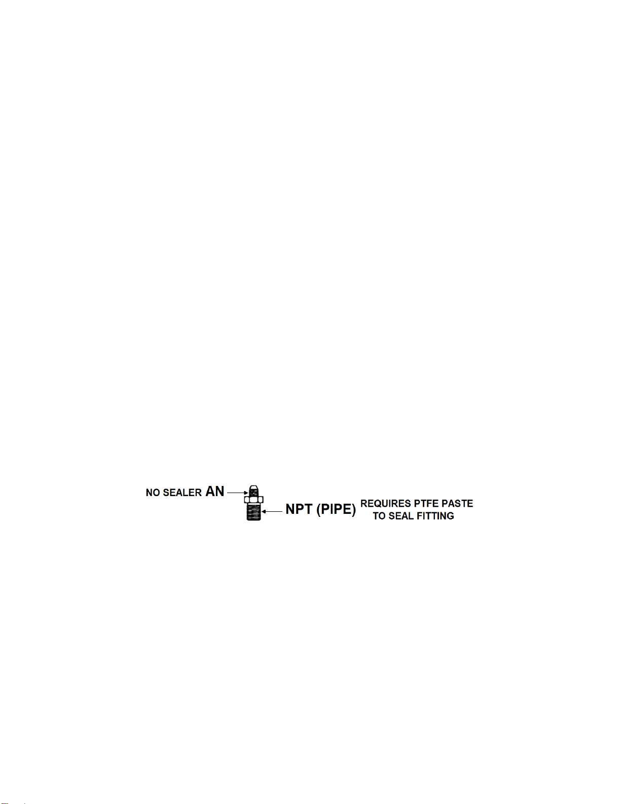
Use PTFE-based thread sealant on pipe-style fittings.
Make sure your engine and related components (ignition, fuel system, and driveline) are in proper working condition.
Do not attempt to start the engine if the nitrous has been injected while the engine was not running. Disable the ignition
and fuel systems (consult owner’s manual) and turn the engine over with the throttle wide open for several revolutions
before attempting to start. Failure to do so can result in extreme engine damage.
Use your NOS nitrous system only at wide-open throttle and at engine speeds above 3000 RPM.
Install a proper engine to chassis ground. Failure to do so may result in an explosive failure of the main nitrous supply
line.
Use a high-quality fuel, as suggested in Chapter 3, Baseline Tuning Suggestions.
Don’ts
Engage your nitrous system with the engine off. Severe engine damage can occur.
Modify NOS nitrous systems (if you need a non-stock item, call NOS Technical Service for assistance)
Overtighten AN type fittings.
Use PTFE Tape on any pipe threads. Pieces of PTFE tape can break loose and become lodged in the nitrous or fuel solenoids or
solenoid filters. Debris lodged in a nitrous or fuel solenoid can cause catastrophic engine failure.
Use sealant of any kind on AN type fittings.
Allow nitrous pressure to exceed 1100 psi. Excessive pressure can cause swelling or in extreme cases failure of the nitrous
solenoid plunger. Solenoid plungers are designed so that pressure-induced failures will prevent the valve from operating. No
leakage should occur with this type of failure.
Inhale nitrous oxide. Death due to suffocation can occur.
Allow nitrous oxide to come in contact with skin. Severe frostbite can occur.
Use octane boosters that contain methanol. Fuel solenoid failure may occur, producing severe engine damage.
Chapter 1 Introduction to Your NOS Nitrous Oxide Kit
1.1 General Information
This nitrous kit was engineered to be a clean and simple installation on 2016-2019 Chevrolet Camaro SS with a 6.2L GM LT1 V8
engine. Power output can be increase from 75 to 150 Rear Wheel Horse Power (RWHP) with the supplied jetting. The system can
support up to 250+ RWHP with optional jetting, but be aware that an increase over 175 RWHP will require an upgrade to the OEM fuel
system in the form of an increased capacity fuel pump or a dedicated, stand-alone, fuel system.

5
Although this system was engineered for the 2016-2019 Camaro SS, it can be installed on any GM LT/LS engine that utilizes an 88mm,
4 bolt Drive-by-Wire or cable operated throttle body, please note that some modification may be required. The wiring and electrical
connections will need to be adapted to the different control system used.
1.2 System Requirements
When used correctly this kit is designed to work with stock 2016-2019 Chevrolet Camaro SS engine and driveline components. The
four jet combinations in this kit generate 75, 100, 125, or 150 RWHP gains. Colder plugs (non-projected tip, non-platinum, Iridium or
fine wire, gapped at .040”) are recommended, NOS utilized Brisk RR12S Spark Plugs during our development. If the jetting is
increased over 175 HP, it is necessary to upgrade the fuel delivery system to ensure safe operation.
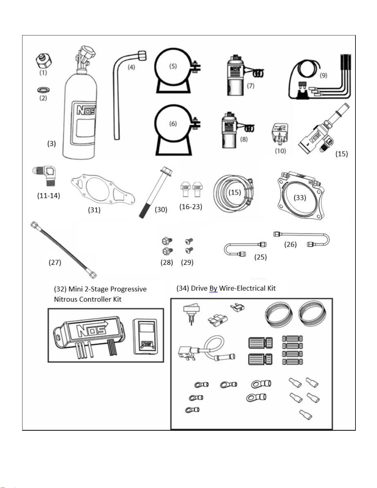
1.3 Kit Components
Before beginning the installation of your NOS kit, compare the components in your kit with those listed in Table 1. If any components
are missing, please contact NOS Technical Support at 1-866-464-6553.
Table 1 - Parts List
Item
Description
Qty
05159NOS
05159BNOS
05166NOS
05166BNOS
1
Bottle Nut Adapter
1
16230NOS
16226NOS
16230NOS
16226NOS
2
Bottle Valve Washer
1
16210NOS
16210NOS
16210NOS
16210NOS
3
Bottle w/ racer safety
1
14745-TPINOS
14745B-TPINOS
14750B-ZR1NOS
14750B-ZR1NOS
4
Blow Down Tube
1
16160NOS
16161NOS
16160NOS
16161NOS
5
Bottle Mounting Bracket, Short
1
14126-SNOS
14126-SNOS
14126-SNOS
14126-SNOS
6
Bottle Mounting Bracket, Long
1
14127-SNOS
14127-SNOS
14127-SNOS
14127-SNOS
7
Cheater N2O Solenoid
1
18000NOS
18000BNOS
18000NOS
18000BNOS
8
Cheater Fuel Solenoid
1
18055NOS
18055BNOS
18055NOS
18055BNOS
9
Relay Wiring Harness
1
15604-SNOS
15604-SNOS
15604-SNOS
15604-SNOS
10
30 Amp Relay
1
15618NOS
15618NOS
15618NOS
15618NOS
11
90 Degree 6AN –1/4” NPT Nitrous Filter
1
15566NOS
15566BNOS
15566NOS
15566BNOS
12
90 Degree 3AN –1/8’ NPT Adapter
1
17650NOS
AT982203ERL
17650NOS
AT982203ERL
13
90 Degree 3AN –1/8’ NPT Adapter
1
17651NOS
AT982203ERL
17651NOS
AT982203ERL
14
90 Degree 4AN –1/8” NPT Adapter
2
17661NOS
AT982204ERL
17661NOS
AT982204ERL
15
Late Model Billet Fuel Line Adapter Black Ano. Alum.
1
17002NOS
17002NOS
17002NOS
17002NOS
16
0.018” Flare Jet
1
13760-18NOS
13760-18NOS
13760-18NOS
13760-18NOS
17
0.021” Flare Jet
1
13760-21NOS
13760-21NOS
13760-21NOS
13760-21NOS
18
0.027” Flare Jet
1
13760-27NOS
13760-27NOS
13760-27NOS
13760-27NOS
19
0.031” Flare Jet
1
13760-31NOS
13760-31NOS
13760-31NOS
13760-31NOS
20
0.035” Flare Jet
1
13760-35NOS
13760-35NOS
13760-35NOS
13760-35NOS
21
0.040” Flare Jet
1
13760-40NOS
13760-40NOS
13760-40NOS
13760-40NOS
22
0.050” Flare Jet
1
13760-50NOS
13760-50NOS
13760-50NOS
13760-50NOS
23
0.057” Flare Jet
1
13760-57NOS
13760-57NOS
13760-57NOS
13760-57NOS
24
6AN 16 ft. Hose
1
15480NOS
15480BNOS
15480NOS
15480BNOS
25
3AN to 3AN Stainless Nitrous Hard Line
1
52R725A
52R665A
52R725A
52R665A
26
3AN to 3AN Stainless Fuel Hard Line
1
52R724A
52R664A
52R724A
52R664A
27
4AN to 4AN 2-FT Hose
1
15231-SNOS
15230B-SNOS
15231-SNOS
15230B-SNOS
28
Screws, Solenoid Mounting 10-32
2
16501-SNOS
16501-SNOS
16501-SNOS
16501-SNOS
29
Screws, Solenoid Mounting 8-32
2
16506-SNOS
16506-SNOS
16506-SNOS
16506-SNOS
30
M6X1X60MM, 10.9 FLANGED HEX HEAD BOLT
4
505R87
505R87
505R87
505R87
31
Solenoid Mounting Bracket
1
49R3419
49R3419
49R3419
49R3419
32
Mini 2-Stage Progressive Nitrous Controller
1
15974NOS
15974NOS
15974NOS
15974NOS
33
Billet Nitrous Plate Assembly for GM LT/LS
1
40R951A
40R951A
40R951A
40R951A
34
Drive By Wire –Electrical Kit
1
85R9801
85R9801
85R9801
85R9801
Rocker Switch
1
1/4” Ring Terminal – Red –18-20 AWG
1
1/4” Female Spade – Red –18-20 AWG
3
25 Amp Fuse ATC (large)
1
15 Amp Fuse ATM (mini)
1
Add-A-Fuse Tap for Mini ATM Fuses
1
Posi-Lock Splice Connector 22-20 AWG
4
5/16” Ring Terminal – Yellow –10-12 AWG
2
5/16” Ring Terminal – Red –18-20 AWG
1
Posi-Twist Connector 10-22 AWG
2
Wire –Red –20AWG
8ft
Wire –Black –20AWG
8ft
6
Figure 1 Component Identification
-Parts Shown are not to scale-

7
Chapter 2 Kit Installation
2.1 Bottle Mounting Instructions
Accurate calibration of your NOS nitrous system depends on the bottle remaining at a stable temperature. Mount the bottle away from
heat sources, such as the engine compartment or exhaust system, and away from windows, where the bottle is exposed to direct
sunlight.
2.2 Bottle Orientation
Bottle placement is critical to the performance of your NOS nitrous system. It is important to understand how the bottle valve and
siphon tube are assembled to properly orient the bottle in your vehicle and ensure that it picks up liquid nitrous while undergoing
acceleration. All nitrous bottles are assembled so that the bottom of the siphon tube is at the bottom of the bottle and opposite the
bottle label (Figure 2).
Whenever the bottle is mounted in a lay-down position, the valve handle must be towards the front of the vehicle with the label facing
up (Figure 3A).
If the bottle is mounted vertically, the valve handle and label must face toward the front of the vehicle (Figure 3B). This orientation will
position the siphon tube at the back of the bottle where the liquid N2O will be during acceleration.
WARNING! DO NOT attempt to remove the siphon tube without completely emptying the bottle of all N2O and pressure.
A bottle mounted upside-down must have the siphon tube removed before use (Figure 3C). Non-siphon bottles can be specially
ordered from NOS.
If the bottle must be mounted parallel to the axles of the vehicle (sideways), the valve handle and label must be angled at approximately
45° toward the front of the vehicle (Figure 3D). This orientation will position the siphon tube toward the rear of the bottle.
NOTE: When using a bottle with a siphon tube, the tall bracket should be at the valve end of the bottle and the short bracket at the
bottom (Figure 3E).
The most efficient mounting is the lay-down position (Figure 3A) with the valve handle toward the front of the vehicle. This position
allows the greatest amount of liquid to be used before the siphon tube begins to pick up gaseous nitrous oxide.
Find a position in the rear of your vehicle that meets your personal preference. Make sure that it meets the guidelines show in Figure 3.
Figure 2 Nitrous Bottle Siphon Tube Orientation Figure 3 Nitrous Bottle Mounting Orientations
2.3 Bottle Installation
Before mounting a nitrous bottle in a racing vehicle intended for use in sanctioned events, check with the sanctioning association for
any rules regarding this subject. Most associations require the bottle to be mounted within the confines of the safety roll cage with the
safety pressure relief cap vented away from the driver’s compartment. This feature is included in this kit.
1. Install the bottle nut adapter and washer on the nitrous bottle, and tighten securely.
2. Slip the bottle mounting brackets onto the nitrous bottle, as shown in Figure 3E.

8
3. Locate the bottle assembly in the desired mounting location, ensuring that the location will provide easy access to the bottle valve,
hose connection, bracket clamp bolts to facilitate bottle changing and through hole of the blow-down tube.
4. Use the assembled bottle/bracket unit as a pattern to mark for drilling the holes. Drill four 11/32” holes in the mounting surface for
the bottle bracket bolts. Make sure the holes are in a position that does not damage other components.
CAUTION! When drilling or punching holes for these fasteners, be aware what components, wires, hoses or fluid reservoirs
are located or routed behind the general area to avoid vehicle or equipment malfunction.
5. Mount the brackets securely to the surface (recommended minimum of 5/16” bolts or No. 12 sheet metal screws).
6. Secure the nitrous bottle in the mounting brackets and tighten the bracket clamps.
7. Route the blow-down tube through the hole in the trunk, install and fasten to the fitting on the bottle valve.
2.4 Solenoid Fittings and Bracket Mounting
1. Apply a small amount of PTFE thread sealant to the NPT threads of the nitrous inlet filter adapter (-6AN to 1/4 NPT 90° adapter
with screen) and insert into the IN side of the nitrous solenoid. Use a bench vise to tighten the fitting at least 1-1/2 turns after finger
tight. See Figure 4 for alignment.
2. Apply a small amount of PTFE thread sealant to the NPT threads of the nitrous outlet adapter (-3AN to 1/8 NPT 90° adapter
without screen) and insert into the OUT side of the nitrous solenoid. Use a bench vise to tighten the fitting at least 1-1/2 turns after
finger tight. See Figure 4 for alignment.
Figure 4 –Nitrous Solenoid Adapter Alignment Figure 5 –Fuel Solenoid Adapter Alignment
3. Apply a small amount of PTFE thread sealant to the NPT threads of the fuel inlet filter adapter (-4AN to 1/8 NPT 90° adapter with
screen) and insert into the IN side of the fuel solenoid. Use a bench vise to tighten the fitting at least 1-1/2 turns after finger tight.
See Figure 5 for alignment.
4. Apply a small amount of PTFE thread sealant to the NPT threads of the fuel outlet adapter (-3AN to 1/8 NPT 90° adapter without
screen) and insert into the OUT side of the fuel solenoid. Use a bench vise to tighten the fitting at least 1-1/2 turns after finger
tight, see Figure 5 for alignment.
-6AN to 1/4 NPT
90° Filter Adapter
-3AN to 1/8 NPT
90° Adapter
-4AN to 1/8 NPT
90° Filter Adapter
-3AN to 1/8 NPT
90° Adapter
9
5. Attach the solenoids to the bracket as shown in Figure 6. Set assembly aside to be used in Section 2.5, Step 9.
Figure 6 –Solenoid bracket assembly
2.5 Kit Plate Installation
WARNING! Do not smoke, carry lighted tobacco, or allow an open flame of any type when working on or near any fuel-related
components. Highly flammable mixtures are always present and may be ignited. Failure to follow these
instructions may result in personal injury.
1. Disconnect negative cable at the battery.
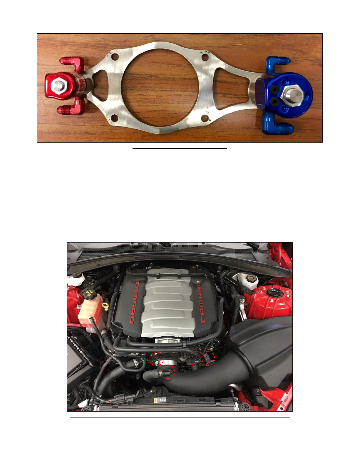
2. Disconnect the two PCV connectors and sound tube (if equipped) from the air inlet tube.
3. Disconnect the mass air flow connector.
4. Using an 8mm or 5/16” nut driver, loosen the air inlet flex tube clamps. Remove the flex tube or entire air cleaner assembly.
Figure 7 –Intake Air Tube Removal (Holley®Intech Shown, but Factory Intake is Similar)

10
5. Using an 8mm socket, remove the throttle body bolts and set throttle body aside.
Figure 8 –Throttle Body Removal
6. Install the nitrous plate and solenoid bracket assembly onto the intake manifold using the new, longer throttle body bolts as shown
in figure 9. Be sure to install the included gasket between the solenoid bracket and the nitrous plate.
Figure 9 –Nitrous Plate & Solenoid Bracket Installation
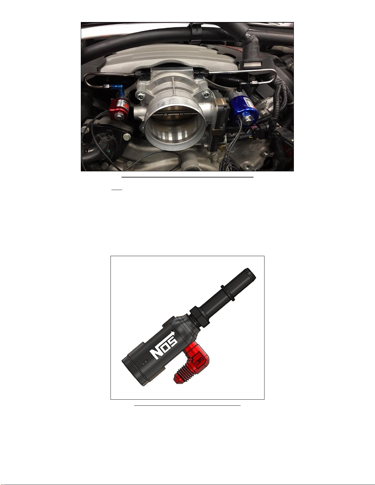
7. Assemble the nitrous and fuel supply lines to the appropriate fittings with the desired jets installed as shown in Figure 10. (See
Chapter 3, table 2 for suggested jetting). Route the supply lines as shown in and connect them to the appropriate solenoid.
NOTE: We highly recommend the smallest (lowest power) jetting supplied as a starting point. Once total system
functionality has been verified, then larger jetting can be installed.
11
Figure 10 –Hardline Routing and Assembled Plate
8. Tighten the hardline fittings and then the throttle body screws. Torque to 106 in./lbs. (~8.8 ft./lbs.).
9. Reinstall the intake tube, all electrical connectors, and PCV connectors.
2.6Fuel and Nitrous Supply Connection
1. Apply a small amount of PTFE thread sealant to the NPT threads of the 90° 1/8”NPT to -4AN fitting, and the 3/8” OE fuel stem.
Tighten down the plug (note: no PTFE sealant is required on the plug since this already has sealant applied) and install it in the
remaining port on the Fuel Tap as shown. Use a bench vise to tighten the fitting at least 1-1/2 turns after finger tight. See figure 11
for orientation.
Figure 11 –Fuel Tap Adapter Orientation
WARNING! Fuel in the fuel system remains under high pressure even after the engine is shut off. Before working on or
disconnecting any of the fuel lines or fuel system components, the fuel pressure must be relieved. Failure to
follow these instructions may result in serious personal injury.

12
2. Once residual fuel pressure is relieved, place clean rags under and around the fuel rail feed line connector and disconnect by using
a 3/8 diameter fuel line disconnect tool. This tool can be found at your local auto parts store. Place the tool inside of the OE line
and slowly pull apart. There may still be residual fuel in the lines so use caution when moving to the next step.
3. Install the 3/8” NOS fuel tap (17002NOS) between the fuel rail and the fuel feed line with the red fuel fitting pointing toward the
firewall. Apply a light coat of blue thread locker on the retention nut and torque 10-12 ft. /lbs. See figure 12.
Figure 12 –Fuel Tap Orientation
4. Remove the passenger’s side engine cover and route the 2 foot fuel line as shown in figure 13. Tighten the -4AN to the 90 degree
adapter on the solenoid and the 90 degree adapter on the fuel tap and reinstall the engine cover being careful not to pinch the fuel
line.
Figure 13 –Fuel Line Routing
5. Plumb your nitrous supply line from the bottle to the 90° -6AN filter adapter, IN side of the nitrous solenoid being careful not to
pinch the line or allow any abrasion from moving parts or exposure to excessive heat.

13
2.7 Electrical System
WARNING! Death or injury may occur from working on a charged electrical system.
1. Disconnect the ground cable from the battery.
2. Install the NOS arming switch in the vehicle’s interior, within easy reach of the driver, and route the provided red and black wires
from the switch to the power distribution box on passenger’s side of the engine bay.
3. Install the relay in the engine compartment so the relay connector’s orange wire will reach the battery (+) terminal located at the
front of the main fuse/relay box.
4. Install the NOS 2-stage mini progressive controller to a secure area. NOS found that behind the passenger’s side headlight, on the
radiator support bar was a good location for the controller.
NOTE: Figure 14 shows the mini 2-stage controller mounted behind the passenger’s side headlight.
Figure 14 –Mini 2-Stage Mounting Location
5. Connect the orange relay wire (with fuse) to the battery (+) terminal located at the front of the main relay/fuse box.
6. Connect one wire from the nitrous solenoid to the large blue wire from the mini 2-stage progressive controller and one wire from
the fuel solenoid to the large red wire from the mini 2-stage progressive controller, using the provided posi-twist connectors (see
assembly diagram on page 14).
7. Join the remaining two solenoid wires to the smaller blue wire coming from the relay harness using the other Posi-Twist connector.
8. Connect the green relay wire to a good chassis ground.
9. Connect the red relay wire to the white wire between the master arming switch (“Load”) and the 2-stage mini controller using one of
the provided Posi-Tap connectors (see assembly diagram on page 16. This tap can be installed close to the Mini 2-Stage
Controller in the engine bay.
10. Connect the “Supply” terminal (supplied red wire from step 2) on the master arming switch to the blue crimp connector on the
provided Add-A-Tap fuse holder. Find a suitable 15 amp fused circuit in the main fuse/relay box in the engine bay to plug into.
Install both the supplied 15 amp mini fuse and the fuse removed from the fuse box into the Add-A-Tap fuse holder.

14
11. Ensure the chosen switched power supply 15 amp fuse location is powered only in the ON/RUN position of the ignition. This can
be verified by using a test light before connecting the Add-A-Tap fuse holder.
12. Connect the digital ground (small black) wire to a clean ground not shared with high voltage grounds. This is the same wire from
step 2 above, the wire from the Earth terminal will be T-taped into this wire using the Posi-Tap connector.
13. Connect the “Earth” terminal on the master arming switch (supplied black wire from step 2) to the digital ground wire coming from
the 2-stage mini controller (small black wire) using one of the provided Posi-Tap connectors (see assembly diagram below).
14. Connect the 2-stage mini progressive ground (large black wire) to a good battery/engine ground using the suppled ring lug
connector.
NOTE: It is important to ensure that a good ground path to the battery is used. This is the high current ground used by the fuel and
nitrous solenoids.
15. Using a supplied Posi-Tap connector (see assembly diagram below), connect the green tach signal wire from the 2-stage mini
progressive controller to the #2 coil driver signal wire (Blue/Violet Wire). This will be one of the wires on the 2 wire connector
located on the ignition coil.
16. (Optional) Using a supplied Posi-Tap connector and coil of 8-ft blue wire, connect the white with blue stripe and white with red
stripe TPS signal wires from the 2-stage mini progressive controller into the TPS signal wire on the throttle pedal inside of the
vehicle (Green/Black Wire). See Figure 15.
NOTE: connecting the TPS signal wire to the pedal does not communicate to the mini 2-stage if the throttle body closes due
to a traction control or torque limiting scenario.
Figure 15 Throttle Pedal Connection
17. Install the relay into the relay connector and reconnect the battery.
NOTE: When connecting the battery, be aware of any excessive arcing or sparks from the battery to the negative cable. This could
be an indication of a wire that has been shorted to ground.

15
Posi-Tap Connector Assembly Posi-Twist Connector Assembly
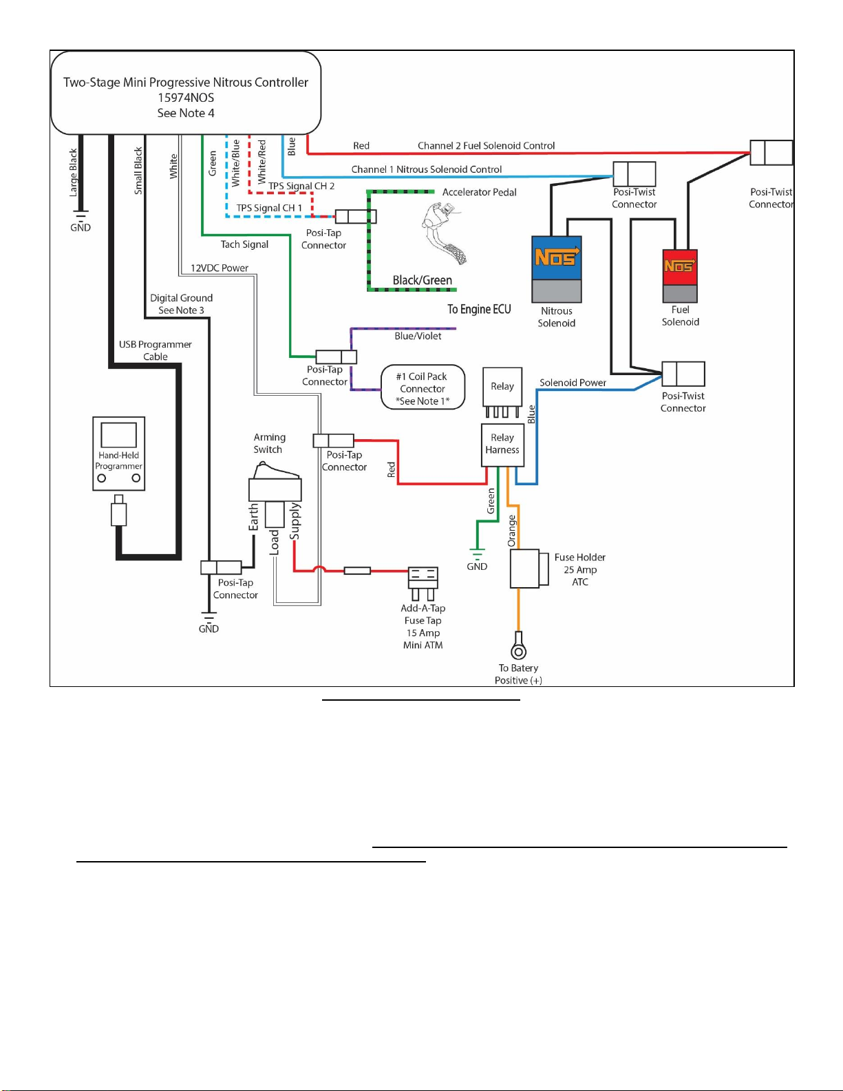
16
Figure 20 Electric Wiring Diagram
2.8 Preparing for Operation
1. Install a fully charged nitrous bottle. The pressure gauge should read 900-1000 psi at operating temperature/pressure.
2. Slowly open the nitrous bottle valve while listening and looking for any leaks at the bottle fittings as well as the fittings on the
solenoids in the engine compartment.
3. If no leaks are found, slightly loosen the -6 AN supply line fitting at the blue nitrous solenoid. Allow the air to leak from the fitting
until nitrous starts to fog out, then retighten the fitting. NOTE: Nitrous is very cold and can cause burning and irritation to the
skin, we recommend wearing gloves during this procedure.
4. Turn the ignition power to the ON position, but do not start the car.
5. Turn the Master Enable switch to the ON position. The red LED should be on now.
6. Connect the hand held programmer to the USB cable and program the unit to the recommended base settings shown in section
2.8.1. Additional instructions are included with the 2-stage mini progressive controller for creating custom settings.
7. Once programming is complete, turn the ignition switch off for 10 seconds, then back to the ON positon; do not start the engine
yet.

17
8. Verify the programmer display shows an “r r”. If display show any other values than “r r”, refer to page 2 of the Mini 2-Stage
controller instructions for more information.
9. You are now ready to drive the car and test the operation of the nitrous system.
WARNING! It is VERY important to use caution and good safety practices when testing and using any nitrous oxide system.
We do not recommend the use of nitrous on any public streets or highways. It is recommended to only test and
use nitrous in a controlled, closed course location, such as a race track.
WARNING! Never activate nitrous with the vehicle in “NEUTRAL” or “PARK”!
WARNING! Never activate nitrous at engine speeds below 3000 RPM, or engine damage may result!
WARNING! SEVERE ENGINE DAMAGE MAY OCCUR IF NITROUS IS ACTIVATED WHILE TRACTION CONTROL DEVICES ARE
ENABLED. TRACTION CONTROL DE-ACTIVATION MUST BE CYCLED EVERY TIME THE IGNITION SWITCH IS
CYCLED.
2.8.1 Programming the Mini 2-Stage Progressive Controller
The following settings are a good baseline from which to start. Additional or Custom settings can be programed by following the User
Guide suppled with the Mini 2-Stage controller.
Switch #1 - toggles through the configuration menu. As you toggle through the configuration menu, the stored value will be displayed.
Use this switch to toggle to the next step in programming mode (Press switch #1, 2 times).
Switch #2 - increments the flashing value that was selected by switch #1.
LED A.B.C - displays the configuration step number and its setting
A = this is the step being programmed
B & C = value for the current configuration step
To enter the programming mode:
Press and hold both switches until “Pro” is displayed. Now release the switches and the unit will automatically go to the first
configuration step.
STEP F. SOLENOID FREQUENCY (Hz) = 20 Display reads; F.20
STEP C.RPM SIGNAL SET-UP = 00 Display reads; C.00
STEP P.RAMP PAUSE MODE = 00 Display reads; P.00
Channel 1 –Nitrous Solenoid Set Up
1. ACTIVATION RPM = 40 (4000rpm)
NOTE: This setting can range from a minimum of any RPM greater than 0 rpm (3000 rpm recommended) up to a
maximum of 9900 rpm. Display reads; 1.40
2. DEACTIVATION RPM = 65 (6500rpm) Display reads; 2.65
NOTE: This setting should be set to 200 RPM below engine rev limiter (maximum of 9900 rpm).
3. DELAY TIME = 0.0 (seconds) Display reads; 3.0.0
Switch #1
Switch #2
A B C

18
4. START % = 10 (10%) Display reads; 4.10
5. RAMP TIME = 0.5 (0.5 seconds) Display reads; 5.0.5
6. END % = 99 (99%) Display reads 6.99
NOTE: (99% = 100 %)
7. CONTROL OUTPUT DELAY TIME = 00 Display reads 7.0.0
8. TPAS MODE = 02 (90% of WOT voltage) Display reads; 8.02
9. TPS SETTING = see below to calibrate this setting
Press switch #2 to read and display the TPS signal. Momentarily press the accelerator pedal completely to the floor and release,
to reach 100% throttle –the unit only needs to see WOT for a fraction of a second. Now press switch #1 to save the displayed
value. (You do not have to be at WOT when you press switch #1 to save.) Engine should not be running, but ignition must be
ON!
Channel 2 –Fuel Solenoid Set Up
1. ACTIVATION RPM = 39 (3900rpm)
NOTE: This setting can range from a minimum of any RPM greater than 0 rpm (3000 rpm recommended) up to a
maximum of 9900 rpm. Display reads; 1.39
2. DEACTIVATION RPM = 65 (6500rpm) Display reads; 2.65
NOTE: This setting should be set to 200 RPM below engine rev limiter (maximum of 9900 rpm).
3. DELAY TIME = 0.0 (seconds) Display reads; 3.0.0
4. START % = 00 (00%) Display reads; 4.00
5. RAMP TIME = 0.0 (0.0 second) Display reads; 5.0.0
6. END % = 99 (99%) Display reads 6.99
NOTE: (99% = 100 %)
7. CONTROL OUTPUT DELAY TIME = 00 Display reads 7.0.0
8. TPAS MODE = 02 (90% of WOT voltage) Display reads; 8.02
9. TPS SETTING = see below to calibrate this setting
Press switch #2 to read and display the TPS signal. Momentarily press the accelerator pedal completely to the floor and release,
to reach 100% throttle –the unit only needs to see WOT for a fraction of a second. Now press switch #1 to save the displayed
value. (You do not have to be at WOT when you press switch #1 to save.) Engine should not be running, but ignition must be
ON!
NOTE: Activating the fuel solenoid before the nitrous solenoid allows the system to recover from the initial drop in fuel
pressure, this avoids a lean condition and allows for the most optimal conditions for the nitrous.
NOTE: The user must continue through the setup for stage 1 and stage 2 until they see END. If the power is shut off, or the
system reset in any way, the changes will not be saved.
19
Chapter 3 Tuning
Table 2 Tuning Suggestions
Configuration
N2O Jetting
Fuel Jetting
Configuration
N2O Jetting
Fuel Jetting
75 RWHP*
.044*
.023*
150 RWHP*
.060*
.042*
100 RWHP*
.050*
.035*
175 RWHP**
.070
.048
125 RWHP*
.055*
.039*
200 RWHP**
.075
.050
*Jetting Included in kit
**Will require an upgraded fuel system
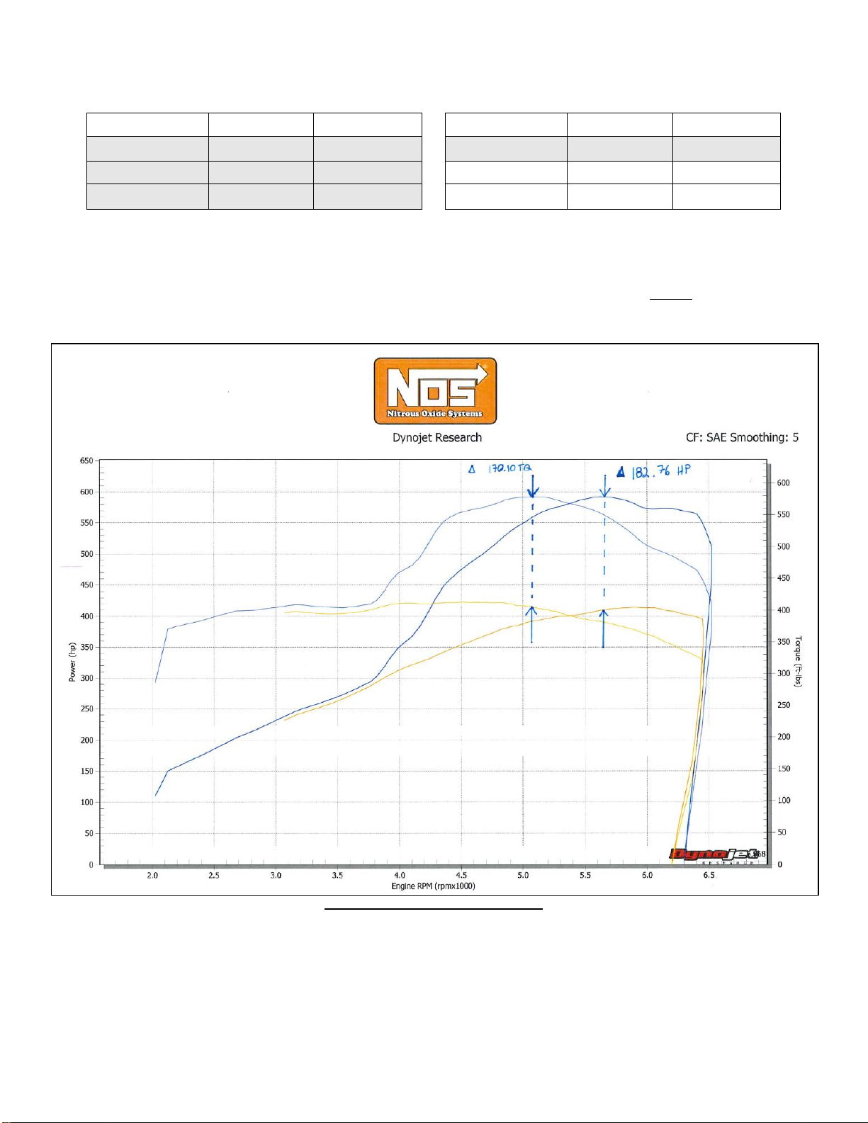
NOTE: Figure 21 shows a 183 Rear Wheel Horsepower increase on Holley’s Dynojet Chassis Dyno. This test was performed on a 2016 Chevrolet
Camaro SS with a 6.2L LT1 engine and a 6-speed manual using 10 gallons of 108 octane race fuel, Brisk RR12S spark plugs, Hooker Black Heart
Exhaust, stock fuel injectors and stock fuel pump. This power level is at the extreme limit of the OEM fuel system. We HIGHLY recommend upgrading
the fuel pump before attempting to run this power level. Severe engine damage can result from prolonged use of running this power level with an OEM
fuel system.
Figure 21 –175HP Shot Dyno Graph
Chapter 4 Determining Optimum System Performance
The jetting combinations included in your nitrous kit are intended to generate power gains of 75 to 150 HP. These combinations are
designed to be used with 950 psi of nitrous bottle pressure and 60 psi of flowing fuel pressure. Spark plug inspection and/or the use of
a wide-band O2sensor can determine optimum system performance. Inspection of the spark plugs should be done on a consistent
basis.

20
1. Perform a dynamometer pull or a full throttle pass down the racetrack. Note the power reading or vehicle mph (not e.t.). Examine
the spark plugs for an indication of lean or rich nitrous/fuel conditions (refer figure 22 to for tips on reading the spark plugs). For
this application, the air/fuel mixtures at WOT tend to be very rich in stock form. You may wish to examine a plug after a NO-nitrous
pass or dyno pull for comparison purposes.
CAUTION! Terminate test immediately if pinging, knocking, detonation is noticed during the test. If engine does not pull hard
(expected HP or torque gains are not observed), terminate test and investigate before continuing.
1A. If spark plugs appear to be excessively rich, decrease the fuel jet size 1 step (ex. 28 to 26 or 26 to 24).
1B. If spark plugs appear to be excessively lean, increase the fuel jet size 1 step.
1C. If spark plugs have a “like new” appearance on the porcelain and electrode, do not make a fuel jetting change.
2. Repeat these steps until the desired mixture is obtained.
How to Read Spark Plugs from a Nitrous Oxide Injected Engine
A. Correct Timing, Mixture, and Spark Plug Heat Range
The ground strap retains a “like new” appearance. The edges are crisp, with no signs of discoloration. The porcelain retains a clear
white appearance with no “peppering” or spotting.
B. Excessively Rich Mixture
The porcelain may be fuel stained, appearing brown or black. In extreme cases, the ground strap, electrode, and porcelain may be
damp with gasoline, or smell of fuel.
C. Detonation
The edges of the ground strap may become rounded. The porcelain has the appearance of being sprinkled with pepper, or may have
aluminum speckles. During heavy detonation, the ground strap tip may burn off. This phenomenon can result from excessive ignition
timing, too high a heat range spark plug, inadequate fuel octane, or excessively lean mixture.
D. Excessively Lean Mixture
The edges of the ground strap may become rounded. Under moderate overheating, the tip of the ground strap can discolor, usually
turning purple, or the entire ground strap can become discolored.
Figure 22 Spark Plug Condition
Chapter 5 Alternate Sensor, Actuator, and Switch Components
1. In some racing applications, “pushbutton solenoid” activation is preferred. In such instances, the solenoid is connected to ground
via a pushbutton momentary switch P/N 15610NOS. For information on wiring options, please call NOS Technical Support at 1-
866-464-6553.
2. Almost all multi-point fuel injection systems are provided with throttle position sensors. NOS has throttle position sensor
controllers that activate the solenoids, according to the sensor voltage output. This form of solenoid activation procedure is
commonly referred as “TPS activation”. Such devices are more accurate than the microswitch. For P/Ns on TPS switches and
information on wiring options, please call NOS Technical Support at 1-866-464-6553.
3. NOS offers fuel pressure safety switches. These switches only allow the nitrous and fuel solenoid to be activated, if a safe fuel
pressure is existent in the enrichment fuel supply system. For information on pressure safety switches and information on wiring
options, please call NOS Technical Support at 1-866-464-6553.
4. Activation of nitrous at low RPM levels can be detrimental to the engine performance and engine life. The RPM window activation
switch only allows the nitrous and fuel solenoid to be activated if a safe RPM value has been reached. Some factory engine
control units cut off the ignition if a maximum RPM level is reached. Although the engine is still at WOT and the solenoids are
activated no nitrous and fuel is combusted. When the engine reaches safe RPM levels ignition is restored but excess fuel and
nitrous are present in the manifold. Some applications may even cut the fuel injector to limit engine RPM. Because the engine is
This manual suits for next models
3
Table of contents
Other Nos Automobile Accessories manuals


Popular Automobile Accessories manuals by other brands


Metra Electronics
Metra Electronics 99-7501 installation instructions

STO N SHO
STO N SHO SNS 288 Installation procedures

Thule
Thule 169 parts list

Mennekes
Mennekes AMTRON Compact 3.7 C2 OPERATING AND INSTALLATION Manual

Rosen
Rosen VoiceCom 2000 installation manual

Black & Decker
Black & Decker TC212FRB instruction manual


