Nos 05183NOS User manual

2005-2008 Chrysler 5.7 Hemi Kit Number 05183NOS
OWNER’S MANUAL
P/N 199R11456

2
CONGRATULATIONS on purchasing your NOS Nitrous Oxide Injection System! Your system is composed of the highest quality
components available.
NOTICE: The installation of Nitrous Oxide Systems, Inc. products signifies that you have read this document and have
agreed to the terms stated within.
It is the purchaser’s responsibility to follow all installation instruction guidelines and safety procedures supplied with the product as it is
received by the purchaser to determine the compatibility of the product with the vehicle or the device the purchaser intends to install the
product on.
Nitrous Oxide Systems Inc. assumes no responsibility for damages occurring from accident, misuse, abuse, improper installation,
improper operation, lack of reasonable care, or all previously stated reasons resulting from incompatibility with other manufacturers’
products.
Nitrous Oxide Systems Inc. assumes no responsibility or liability for damages incurred by the use of products manufactured or sold by
Nitrous Oxide Systems Inc. on vehicles used for competition or racing.
Nitrous Oxide Systems Inc. neither recommends nor condones the use of products manufactured or sold by Nitrous Oxide Systems Inc.
on vehicles, which may be driven on public roads or highways, and assumes no responsibility for damages incurred by such use.
NOS nitrous oxide is legal for use in most states when used in accordance with state and local traffic laws. NOS does not recommend
or condone the use of its products in illegal racing activities.
NOS has not pursued California Air Research Board (CARB) exemptions for its kits, hence, they are not legal for use on pollution-
controlled vehicles in California. A correctly installed NOS nitrous system should not alter the emission control performance of your
vehicle under standard EPA test cycle conditions.
HAZARDS DEFINED
This manual presents step-by-step instructions that describe the process of installing your NOS Nitrous Oxide Injection System. These
procedures provide a framework for the installation and operation of this kit. Parts are referenced by name and number to avoid
confusion. Within the instructions, you are advised of potential hazards, pitfalls, and problems to avoid. The following examples
explain the various hazard levels:
WARNING! Failure to comply with instructions may result in injury or death.
CAUTION! Failure to comply with instructions may result in damage to equipment.
NOTE: This information is important, needs to be emphasized, and is set apart from the rest of the text.
HINT: These special instructions provide a handy work tip.
NITROUS OXIDE INJECTION SYSTEM SAFETY TIPS
WARNINGS
IT IS NOT LEGAL TO ENGAGE NITROUS OXIDE INJECTION SYSTEMS ON PUBLIC ROADS OR HIGHWAYS.
NITROUS OXIDE INJECTION SYSTEMS ARE ONLY TO BE ENGAGED DURING SANCTIONED COMPETITION OR
RACING EVENTS.
Do not attempt to start the engine if the nitrous has been injected while the engine was not running. Disable the ignition and
fuel systems (consult owner’s manual) and turn the engine over with the throttle wide open for several revolutions before
attempting to start. Failure to do so can result in extreme engine damage.
Never permit oil, grease, or any other readily combustible substances to come in contact with cylinders, valves, solenoids,
hoses, and fittings. Oil and certain gases (such as oxygen and nitrous oxide) may combine to produce a highly flammable
condition.
Never interchange nitrous and fuel solenoids. Failure to follow these simple instructions can result in extreme engine
damage and/or personal injury.
Never drop or violently strike the bottle. Doing so may result in an explosive bottle failure.
Never change pressure settings of safety relief valve on the nitrous bottle valve. Increasing the safety relief valve pressure
settings may create an explosive bottle hazard.

3
Please note that the NOS bottle label has changed to a two-part assembly. The first label is already located on the bottle.
Upon filling your bottle with nitrous oxide, apply the (second) material information label in the area indicated in the picture to
the right.
NOTE: The material information decal is located in the same
plastic bag as the bottle.
WARNING! Once the nitrous bottle has been filled, it must be
shipped according to the applicable transportation and shipping
regulations!
Do not deface or remove any markings, which are used for
content identification.
Nitrous bottle valves should always be closed when the system
is not being used.
Notify the supplier of any condition that may have permitted any
foreign matter to enter the valve or bottle.
Keep the valves closed on all empty bottles to prevent
accidental contamination.
After storage, open the nitrous bottle valve for an instant to
clear the opening of any possible dust or dirt.
It is important that all threads on the valves and solenoids are properly mated. Never force connections that do not fit
properly.
TABLE OF CONTENTS
WHAT IS NITROUS OXIDE? ...................................................................................................... 4
DO’S AND DON’TS OF NITROUS OXIDE.................................................................................. 4
Chapter 1 Introduction to Your NOS Nitrous Oxide Kit......................................................... 4
1.1 General Information ...........................................................................................................4
1.2 System Requirements........................................................................................................5
1.3 Kit Components..................................................................................................................5
Chapter 2 Kit Installation.......................................................................................................... 7
2.1 Bottle Mounting Instructions............................................................................................... 7
2.2 Bottle Orientation ...............................................................................................................7
2.3 Bottle Installation................................................................................................................7
2.4 05183NOS Kit Plate Installation.........................................................................................8
2.5 05183NOS Solenoid Mounting........................................................................................... 8
2.6 Electrical System.............................................................................................................. 11
2.7 Preparing for Operation.................................................................................................... 13
2.7.1 Programming the Mini 2-Stage Progressive Controller .............................................. 14
Chapter 3 Tuning .................................................................................................................... 16
Chapter 4 Determining Optimum System Performance ...................................................... 16
Chapter 5 Alternate Sensor, Actuator, and Switch Components ....................................... 17
Chapter 6 Routine Maintenance ............................................................................................ 18
6.1 Nitrous Solenoid Filter...................................................................................................... 18
6.2 Nitrous Solenoid Plunger.................................................................................................. 18
6.2.1 General Information....................................................................................................18
6.2.2 Nitrous Solenoid Plunger Disassembly and Inspection............................................... 18
Appendix A Troubleshooting Guide...................................................................................... 20
Nitrous Oxide Accessories ..................................................................................................... 22

4
WHAT IS NITROUS OXIDE?
NITROUS OXIDE…
…Is a cryogenic gas composed of nitrogen and oxygen molecules
…Is 36% oxygen by weight
…Is non-flammable by itself
…Is stored as a compressed liquid
…Exists in two grades—U.S.P. and Nitrous Plus:
U.S.P. is medical grade nitrous oxide; its common use is dental and veterinary anesthesia. It is also commonly used as a
propellant in canned whipped cream. U.S.P. is not available to the public.
Nitrous Plus differs from U.S.P. in that it contains trace amounts of Sulphur dioxide added to prevent substance abuse. Nitrous
Plus is intended for automotive applications and is available for sale to the public.
In automotive applications, Nitrous Plus and fuel are injected into the engine’s intake manifold, producing the following results:
Lowers engine intake air temperature, producing a dense inlet charge.
Increases the oxygen content of the inlet charge (air is only 22 percent oxygen by weight).
Increases the rate at which combustion occurs in the engine’s cylinders.
DO’S AND DON’TS OF NITROUS OXIDE
Do’s
Read all instructions before attempting to install your NOS nitrous system.
Make sure your fuel delivery system is adequate for the nitrous jetting you have chosen. Inadequate fuel pressure or flow will
result in engine damage.
Use 14 gauge (minimum) wire when installing electrical system components.
Use high-quality connections at all electrical joints.
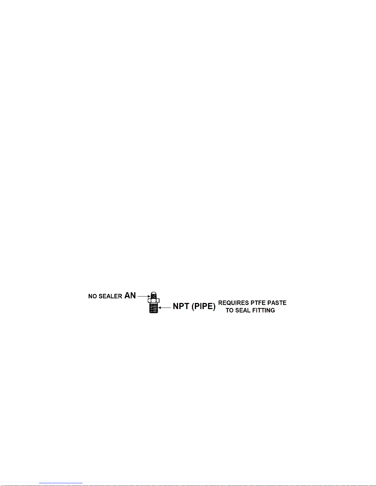
Use PTFE-based paste on pipe-style fittings.
Make sure your engine and related components (ignition, carburetor, and driveline) are in proper working condition.
Do not attempt to start the engine if the nitrous has been injected while the engine was not running. Disable the ignition
and fuel systems (consult owner’s manual) and turn the engine over with the throttle wide open for several revolutions
before attempting to start. Failure to do so can result in extreme engine damage.
Use your NOS nitrous system only at wide-open throttle and at engine speeds above 3000 RPM.
Install a proper engine to chassis ground. Failure to do so may result in an explosive failure of the main nitrous supply
line.
Use a high-quality fuel, as suggested in Chapter 3, Baseline Tuning Suggestions.
Don’ts
Engage your nitrous system with the engine off. Severe engine damage can occur.
Modify NOS nitrous systems (if you need a non-stock item, call NOS Technical Service for assistance)
Overtighten AN type fittings.
Use PTFE Tape on any pipe threads. Pieces of PTFE tape can break loose and become lodged in the nitrous or fuel solenoids or
solenoid filters. Debris lodged in a nitrous or fuel solenoid can cause catastrophic engine failure.
Use sealant of any kind on AN type fittings.
Allow nitrous pressure to exceed 1100 psi. Excessive pressure can cause swelling or in extreme cases failure of the nitrous
solenoid plunger. Solenoid plungers are designed so that pressure-induced failures will prevent the valve from operating. No
leakage should occur with this type of failure.
Inhale nitrous oxide. Death due to suffocation can occur.
Allow nitrous oxide to come in contact with skin. Severe frostbite can occur.
Use octane boosters that contain methanol. Fuel solenoid failure may occur, producing severe engine damage.
Chapter 1 Introduction to Your NOS Nitrous Oxide Kit
1.1 General Information
Kit Number 05183NOS was engineered to be a clean, simple installation on a Chrysler vehicle with a 2005-2008 Chrysler 5.7L HEMI.
Power output can be increased from 75 to 150 Rear Wheel Horse Power (RWHP) with the supplied jetting. The system can support up
to 250 RWHP with optional jetting, but be aware that an increase over 100 RWHP will require an upgrade to the OEM fuel system in the
form of larger injectors, increased capacity fuel pump or a dedicated, stand-alone fuel system.

5
1.2 System Requirements
When used correctly, Kit Number 05183NOS is designed to work with stock 5.7L Hemi internal engine and driveline components. The
four jet combinations in this kit generate approximately 75, 100, 125, or 150 RWHP gains. Colder spark plugs (no platinum, Iridium or
fine wire) are recommended. If the jetting is increased over 100 HP, it is necessary to upgrade the fuel delivery system to ensure safe
operation.
1.3 Kit Components
Before beginning the installation of your NOS kit, compare the components in your kit with those listed in Table 1.
Table 1 Kit Number 05183NOS Parts List
Item
Description
Quantity
NOS P/N
(1)
Bottle Nut Adapter
1
16230NOS
(2)
Bottle Valve Washer
1
16210NOS
(3)
10 lb. Bottle w/ racer safety
1
14745-TPINOS
(4)
Blow Down Tube
1
16160NOS
(5)
Bottle Mounting Bracket, Short
1
14126-SNOS
(6)
Bottle Mounting Bracket, Long
1
14127-SNOS
(7)
N2O Cheater Solenoid
1
18000NOS
(8)
Cheater Fuel Solenoid
1
18055NOS
(9)
Relay Wiring Harness
1
15604-SNOS
(10)
30 Amp Relay
1
15618NOS
(11)
6AN –1/4NPT Nitrous Filter (Blue)
1
15564NOS
(12)
4AN –1/8” NPT 90° Fuel Filter (Red)
1
15571NOS
(13)
3AN –1/8” NPT Adapter (Blue)
1
17952NOS
(14)
3AN –1/8” NPT Adapter (Red)
1
17953NOS
(15)
0.028” Flare Jet
1
13760-28NOS
(16)
0.030” Flare Jet
1
13760-30NOS
(17)
0.033” Flare Jet
1
13760-33NOS
(18)
0.037” Flare Jet
1
13760-37NOS
(19)
0.038” Flare Jet
1
13760-38NOS
(20)
0.040” Flare Jet
1
13760-40NOS
(21)
0.044” Flare Jet
1
13760-44NOS
(22)
0.050” Flare Jet
1
13760-50NOS
(23)
6AN 14 ft. Hose (Blue)
1
15475NOS
(24)
3/8 OE Fuel Line Adapter
1
17002NOS
(25)
MOPAR Nitrous Plate
1
40R944-1
(26)
Screws, Solenoid Mounting 10-32
2
16501-SNOS
(27)
Screws, Solenoid Mounting 8-32
2
16506-SNOS
(28)
Throttle Body Bolts M6-1 x 60mm
4
505R87
(29)
Throttle Body Bolts for Composite Manifold
4
5R2546
(30)
Solenoid Mounting Bracket
1
49R3405
(31)
Gauge Adapter (Blue)
1
16104NOS
(32)
Nitrous Gauge
1
15910NOS
(33)
Mini 2-Stage Progressive Nitrous Controller
1
15974NOS
(34)
Drive By Wire –Electrical Kit
1
85R9801
(35)
-4 AN 18” Fuel Supply Hose
1
15221NOS
(36)
-3 AN 12” Fuel Supply Hose
1
15031NOS
(37)
-3 AN 12” Nitrous Supply Hose
1
15030NOS
Rocker Switch
1
89R687
1/4” Ring Terminal –Red –18-20 AWG
1
1/4” Female Spade – Red –18-20 AWG
3
25 Amp Fuse ATC (large)
1
15 Amp Fuse ATM (mini)
1
Add-A-Fuse Tap for Mini ATM Fuses
1
Posi-Lock Splice Connector 22-20 AWG
4
5/16” Ring Terminal – Yellow –10-12 AWG
2
5/16” Ring Terminal – Red –18-20 AWG
1
Posi-Twist Connector 10-22 AWG
2
Wire –Red –20AWG
8ft
Wire –Black –20AWG
8ft

6
FIGURE 1 –PARTS INCLUDED IN KIT
-Parts Shown are not to scale-

7
Chapter 2 Kit Installation
2.1 Bottle Mounting Instructions
Accurate calibration of your NOS nitrous system depends on the bottle remaining at a stable temperature. Mount the bottle away from
heat sources, such as the engine compartment or exhaust system, and away from windows, where the bottle is exposed to direct
sunlight.
2.2 Bottle Orientation
Bottle placement is critical to the performance of your NOS nitrous system. It is important to understand how the bottle valve and
siphon tube are assembled to properly orient the bottle in your vehicle and ensure that it picks up liquid nitrous while undergoing
acceleration. All nitrous bottles are assembled so that the bottom of the siphon tube is at the bottom of the bottle and opposite the
bottle label (Figure 2).
Whenever the bottle is mounted in a lay-down position, the valve handle must be towards the front of the vehicle with the label facing
up (Figure 3A).
If the bottle is mounted vertically, the valve handle and label must face toward the front of the vehicle (Figure 3B). This orientation will
position the siphon tube at the back of the bottle where the liquid N2O will be during acceleration.
WARNING! DO NOT attempt to remove the siphon tube without completely emptying the bottle of all N2O and pressure.
A bottle mounted upside-down must have the siphon tube removed before use (Figure 3C). Non-siphon bottles can be specially
ordered from NOS.
If the bottle must be mounted parallel to the axles of the vehicle (sideways), the valve handle and label must be angled at approximately
45° toward the front of the vehicle (Figure 3D). This orientation will position the siphon tube toward the rear of the bottle.
NOTE: When using a bottle with a siphon tube, the tall bracket should be at the valve end of the bottle and the short bracket at the
bottom (Figure 3E).
The most efficient mounting is the lay-down position (Figure 3A) with the valve handle toward the front of the vehicle. This position
allows the greatest amount of liquid to be used before the siphon tube begins to pick up gaseous nitrous oxide.
Find a position in the rear of your vehicle that meets your personal preference. Make sure that it meets the guidelines show in Figure 3.
Figure 2 Nitrous Bottle Siphon Tube Orientation Figure 3 Nitrous Bottle Mounting Orientations
2.3 Bottle Installation
Before mounting a nitrous bottle in a racing vehicle intended for use in sanctioned events, check with the sanctioning association for
any rules regarding this subject. Most associations require the bottle to be mounted within the confines of the safety roll cage with the
safety pressure relief cap vented away from the driver’s compartment. This feature is included in the 05183NOS kit.
1. Install the bottle nut adapter and washer on the nitrous bottle, and tighten securely.

8
2. Slip the bottle mounting brackets onto the nitrous bottle, as shown in Figure 3E.
3. Locate the bottle assembly in the desired mounting location, ensuring that the location will provide easy access to the bottle valve,
hose connection, bracket clamp bolts to facilitate bottle changing and through hole of the blow-down tube.
4. Use the assembled bottle/bracket unit as a pattern to mark for drilling the holes. Drill four 11/32” holes in the mounting surface for
the bottle bracket bolts. Make sure the holes are in a position that does not damage other components.
CAUTION! When drilling or punching holes for these fasteners, be aware what components, wires, hoses or fluid reservoirs
are located or routed behind the general area to avoid vehicle or equipment malfunction.
5. Mount the brackets securely to the surface (recommended minimum of 5/16” bolts or No. 12 sheet metal screws).
6. Secure the nitrous bottle in the mounting brackets and tighten the bracket clamps.
7. Route the blow-down tube through the hole in the trunk, install and fasten to the fitting on the bottle valve.
2.4 Throttle Body Plate Installation
WARNING! Do not smoke, carry lighted tobacco, or allow an open flame of any type when working on or near any fuel-related
components. Highly flammable mixtures are always present and may be ignited. Failure to follow these
instructions may result in personal injury.
1. Disconnect negative cable at the battery.
2. Remove the engine cover (if equipped).
3. Disconnect the Intake Air Temp (IAT) Sensor, throttle body connection, and vacuum hose.
4. Using an 8mm or 5/16” nut driver, loosen the air inlet flex tube clamps. Remove the flex tube or entire air cleaner assembly.
5. Using a 10mm socket, remove the throttle body bolts and set throttle body aside.
6. Install the nitrous plate between the throttle body and intake manifold making sure the O-ring to the nitrous plate faces outward
toward the throttle body.
7. Reinstall the throttle body using the new, longer, throttle body screws. Torque to 106 in./lbs. (~8.8 ft./lbs.). Reinstall the air cleaner
assembly.
NOTE: We highly recommend installing the smallest (lowest power) jetting supplied as a starting point. Once
total system functionality has been verified, then larger jetting can be installed.
8. Reconnect the throttle body connection, air temp sensor, and vacuum hose.
NOTE: Intake hose will need to remain off throttle body in order to successfully complete Mini 2-Stage programming.
2.5 Solenoid Mounting
1. Apply a small amount of PTFE thread sealant to the NPT threads of the nitrous filter adapter (blue straight -6 adapter with
screen) and insert into the IN side of the blue nitrous solenoid. Use a bench vise to tighten the fitting at least 1-1/2 turns after
finger tight. See Figure 4.
2. Apply a small amount of PTFE thread sealant to the NPT threads of the blue nitrous outlet fitting and insert into the OUT side of
the blue nitrous solenoid. Use a bench vise to tighten the fitting at least 1-1/2 turns after finger tight. See Figure 4.

9
Figure 4 Figure 5
3. Apply a small amount of PTFE thread sealant to the NPT threads of the fuel filter adapter (red 90° adapter) and insert into the IN
side of the red fuel solenoid. Use a bench vise to tighten the fitting at least 1-1/2 turns after finger tight, Figure 5 for alignment.
4. Apply a small amount of PTFE thread sealant to the NPT threads of the red fuel adapter and insert into the OUT side of the fuel
solenoid. Use a bench vise to tighten the fitting at least 1-1/2 turns after finger tight, see Figure 5.
5. Attach the solenoids to the bracket as shown in Figure 6.
Figure 6
6. Loosen the 8mm valve cover bolt and 8mm intake manifold bolt and install the solenoid bracket in the location shown in Figure 7.

10
Figure 7
7. Route the short nitrous and fuel supply lines from the solenoids, between the EGR tube and water pump and into the nitrous plate.
8. Route the nitrous supply line from the bottle to the blue straight adapter, IN side of the nitrous solenoid being careful not to pinch
the line or allow any abrasion from moving parts in the vehicle or exposure to excessive heat.
WARNING! Fuel in the fuel system remains under high pressure even after the engine is shut off. Before working on or
disconnecting any of the fuel lines or fuel system components, the fuel pressure must be relieved. Failure to
follow these instructions may result in personal injury.
9. To tap into the factory fuel system a specialized tool must be used to remove the OE fuel line from the fuel rail. This tool can be
picked up at your local auto parts store. Refer to the tools instructions for proper use to avoid injury. Apply PTFE paste onto the
threads of the supplied 1/8” NPT quick connect line adapter, plug, and 1/8 NPT to -4 adapter. Assemble the fuel tap as shown in
Figure 8. Once you have removed the 3/8 OE fuel line from the fuel rail, connect the assembled fuel tap onto the 3/8” diameter
fuel rail adapter and tighten. Reattach your OE fuel line which runs from the chassis onto the NOS fuel tap.
Figure 8

11
10. Run the supplied fuel hose (red nuts) from the NOS fuel tap adapter to the red 90° adapter on your fuel solenoid. NOTE: Be
aware that some fuel can come out of the hose so use caution when routing this hose to your solenoid.
2.6 Electrical System
Refer to Figure 10 and the procedures in this section for electrical system installation.
WARNING! Death or injury may occur from working on a charged electrical system.
1. Disconnect the ground cable from the battery.
2. Install the NOS arming switch in the vehicle’s interior, within easy reach of the driver, and route the provided red and black wires
from the switch to the power distribution box on passenger’s side of the engine bay.
2.1 There is a body grommet located on the vehicles fire wall, locate it and use this to access the engine bay from the vehicles
cabin.
3. Install the relay in the engine compartment so the relay connector’s orange wire will reach the battery (+) terminal located at the
front of the main fuse/relay box.
4. Install the NOS 2-stage mini progressive controller in the engine compartment near the main fuse/relay box and route the white
wire to the master arming switch in the vehicle interior. This is also a good time to route the USB cable into the interior if desired.
4.1 Note; the progressive controller can be mounted with Hook & Loop, or double sided tape to the side of the fuse box between
the box and fender. This allows any excess wire to be positioned below the controller under the fuse box.
5. Connect the orange relay wire (with fuse) to the battery (+) terminal located at the front of the main relay/fuse box.
6. Connect one wire from the nitrous solenoid together with the large blue wire from the mini 2-stage progressive controller, using
one of the provided Posi-Twist connectors (see Figure 9).
7. Connect one wire from the fuel solenoid together with the large red wire from the mini 2-stage progressive controller, using one of
the provided Posi-Twist connectors (see Figure 9).
8. Connect the green relay wire to a good chassis ground.
8.1 An engine to chassis ground cable is located on the shock tower, behind the fuse box. This is an ideal location to connect the
green relay and large black progressive controller wires using the suppled ring connectors.
9. Connect the red relay wire to the white wire (same wire as described in step 4 above) between the master arming switch (“Load”)
and the 2-stage mini controller using one of the provided Posi-Tap connectors (see Figure 9). This tap can be installed close to the
Mini 2-Stage Controller in the engine bay.
10. Connect the “Supply” terminal (supplied red wire from step 2) on the master arming switch to the blue crimp connector on the
provided Add-A-Tap fuse holder. Find a suitable 15 amp fused circuit in the main fuse/relay box in the engine bay to plug into.
Install both the supplied 15 amp mini fuse and the fuse removed from the fuse box into the Add-A-Tap fuse holder.
10.1 Ensure the chosen switched power supply 15 amp fuse location is powered only in the ON/RUN position of the ignition. This
can be verified by using a test light before connecting the Add-A-Tap fuse holder.
10.1.1 Fuse number 2 & 5 are good candidates for use with the Add-A-Tap fuse holder.
11. Connect the digital ground (small black) wire to a clean ground not shared with high voltage grounds. This is the same wire from
step 2 above, the wire from the Earth terminal will be T-taped into this wire using the Posi-Tap connector.
12. Connect the “Earth” terminal on the master arming switch (supplied black wire from step 2) to the digital ground wire coming from
the 2-stage mini controller (small black wire) using one of the provided Posi-Tap connectors (see Figure 9).
13. Connect the 2-stage mini progressive ground (large black wire) to a good battery/engine ground using the suppled ring lug
connector.
13.1 It is important to ensure that a good ground path to the battery is used. This is the high current ground used by the fuel and
nitrous solenoids.
13.1.1 An engine to chassis ground cable is located on the shock tower, behind the fuse Box. This is an ideal location to
connect the green relay and large black progressive controller wires using the suppled ring connectors.

12
14. Using a supplied Posi-Tap connector, connect the green tach signal wire from the 2-stage mini progressive controller to the #2 or
#4 coil driver signal wire (#1-Dark Blue & Tan, #3-Dark Blue & Grey). This will be one of the wires on the 4 wire connector located
on the ignition coil.
15. Using a supplied Posi-Tap connector, connect the white with blue stripe TPS signal wire from the 2-stage mini progressive
controller into the TPS signal wire on the throttle body. This will be a brown and orange wire located on the connector at the
passenger’s side of the throttle body.
16. Install the relay into the relay connector and reconnect the battery.
NOTE: When connecting the battery, be aware of any excessive arcing or sparks from the battery to the negative cable. This could
be an indication of a wire that has been shorted to ground.
Posi-Tap Connector Assembly Posi-Twist Connector Assembly
Figure 9

13
Figure 10 Electric Wiring Diagram
2.7 Preparing for Operation
1. Install a fully charged nitrous bottle. The pressure gauge should read 900-1000 psi at operating temperature/pressure.
2. Slowly open the nitrous bottle valve while listening and looking for any leaks at the bottle fittings as well as the fittings on the
solenoids in the engine compartment.
3. If no leaks are found, slightly loosen the -6 AN supply line fitting at the blue nitrous solenoid. Allow the air to leak from the fitting
until nitrous starts to fog out, then retighten the fitting. NOTE: Nitrous is very cold and can cause burning and irritation to the
skin, we recommend wearing gloves during this procedure.

14
4. Turn the ignition power to the ON position, but do not start the car.
5. Turn the Master Enable switch to the ON position. The red LED should be on now.
6. Connect the hand held programmer to the USB cable and program the unit to the recommended base settings shown in section
2.7.1. Additional instructions are included with the 2-stage mini progressive controller for creating custom settings.
7. Once programming is complete, turn the ignition switch off for 10 seconds, then back to the ON positon; do not start the engine
yet.
8. Verify the programmer display shows an “r r”. If display show any other values than “r r”, refer to page 2 of the Mini 2-Stage
controller instructions for more information.
9. You are now ready to drive the car and test the operation of the nitrous system.
WARNING! It is VERY important to use caution and good safety practices when testing and using any nitrous oxide system.
We do not recommend the use of nitrous on any public streets or highways. It is recommended to only test and
use nitrous in a controlled, closed course location, such as a race track.
WARNING! Never activate nitrous with the vehicle in “NEUTRAL” or “PARK”!
WARNING! Never activate nitrous at engine speeds below 3000 RPM, or engine damage may result!
WARNING! SEVERE ENGINE DAMAGE MAY OCCUR IF NITROUS IS ACTIVATED WHILE TRACTION CONTROL DEVICES ARE
ENABLED. TRACTION CONTROL DE-ACTIVATION MUST BE CYCLED EVERY TIME THE IGNITION SWITCH IS
CYCLED.
2.7.1 Programming the Mini 2-Stage Progressive Controller
The following settings are a good baseline from which to start. Additional or Custom settings can be programed by following the User
Guide suppled with the Mini 2-Stage controller.
Switch #1 –toggles through the configuration menu. As you toggle through the configuration menu, the stored value will be displayed.
Use this switch to toggle to the next step in programming mode (Press switch #1, 2 times).
Switch #2 –increments the flashing value that was selected by switch #1.
LED A.B.C –displays the configuration step number and its setting
A = this is the step being programmed
B & C = value for the current configuration step
To enter the programming mode:
Press and hold both switches until “Pro” is displayed. Now release the switches and the unit will automatically go to the first
configuration step.
STEP F. SOLENOID FREQUENCY (Hz) = 20 Display reads: F.20
STEP C.RPM SIGNAL SET-UP = 00 Display reads: C.00
STEP P.RAMP PAUSE MODE = 00 Display reads: P.00
Switch #1
Switch #2
A B C

15
STAGE 1 NITROUS SOLENOID CONTROL
1. ACTIVATION RPM = 40 (4000rpm)
NOTE: This setting can range from a minimum of any RPM greater than 0 rpm (4000 rpm recommended) up to a
maximum of 9900 rpm. Display reads: 1.40
2. DEACTIVATION RPM = 65 (6500rpm) Display reads: 2.65
NOTE: This setting should be set to 200 RPM below engine rev limiter (maximum of 9900 rpm).
3. DELAY TIME = 00 (zero seconds) Display reads: 3.0.0
4. START % = 20 (20%) Display reads: 4.00
5. RAMP TIME = 00 (0.0 seconds) Display reads: 5.2.0
6. END % = 99 (99%) Display reads: 6.99
NOTE: (99% = 100 %)
7. CONTROL OUTPUT DELAY TIME = 00 Display reads: 7.0.0
8. TPAS MODE = 02 (90% of WOT voltage) Display reads: 8.02
9. TPS SETTING = see below to calibrate this setting
Press switch #2 to read and display the TPS signal. Momentarily open the throttle blade by hand, to reach 100% throttle –the unit
only needs to see WOT for a fraction of a second. Now press switch #1 to save the displayed value. (You do not have to be at
WOT when you press switch #1 to save.) Engine should not be running, but ignition must be ON! Wait to install intake hose
until stage 2 is complete.
STAGE 2 FUEL SOLENOID CONTROL
1. ACTIVATION RPM = 33 (3300rpm)
NOTE: This setting can range from a minimum of any RPM greater than 0 rpm (3300 rpm recommended) up to a
maximum of 9900 rpm. Display reads: 1.38
2. DEACTIVATION RPM = 65 (6500rpm) Display reads: 2.65
NOTE: This setting should be set to 200 RPM below engine rev limiter (maximum of 9900 rpm).
3. DELAY TIME = 00 (zero seconds) Display reads: 3.0.0
4. START % = 20 (20%) Display reads: 4.20
5. RAMP TIME = 20 (2.0 seconds) Display reads: 5.0.0
6. END % = 99 (99%) Display reads: 6.99
NOTE: (99% = 100 %)
7. CONTROL OUTPUT DELAY TIME = 00 Display reads: 7.0.0
8. TPAS MODE = 02 (90% of WOT voltage) Display reads: 8.02
9. TPS SETTING = see below to calibrate this setting
Press switch #2 to read and display the TPS signal. Momentarily open the throttle blade by hand, to reach 100% throttle –the unit
only needs to see WOT for a fraction of a second. Now press switch #1 to save the displayed value. (You do not have to be at
WOT when you press switch #1 to save.) Engine should not be running, but ignition must be ON! You may now install the
intake tube onto the throttle body and secure it.
NOTE: Activating the fuel solenoid before the nitrous solenoid allows the system to recover from the initial drop in fuel
pressure, this avoids a lean condition and allows for the most optimal conditions for the nitrous.
NOTE: The user must continue through the setup for stage 1 and stage 2 until they see END. If the power is shut off, or the
system reset in any way, the changes will not be saved.

16
Chapter 3 Tuning
Table 2 Tuning Suggestions for NOS Kit Number 05183NOS
Configuration
N2O Jetting
Fuel Jetting
Configuration
N2O Jetting
Fuel Jetting
75 RWHP*
37*
28*
150 RWHP**
50*
38*
100 RWHP*
40*
30*
175 RWHP**
58
44
125 RWHP**
44*
33*
200 RWHP**
67
51
*Jetting Included in kit
**May require an upgraded fuel system
NOTE: It is recommended to install one to two steps colder, non-projected tip, non-Iridium or other fine wire spark plugs
when using Nitrous Oxide.
Figure 11 shows a 183 Rear Wheel Horsepower increase on Holley’s Dynojet Chassis Dyno. This test was ran on a 2009 Dodge
Challenger with a 5.7L Hemi using 108 octane race fuel, Brisk RR12S spark plugs, Hooker Black Heart Exhaust, stock fuel injectors
and stock fuel pump. This power level is at the extreme limit of the OEM fuel system. We HIGHLY recommend upgrading the fuel
pump before attempting to run this power level. Severe engine damage can result from running this power level with an OEM fuel
system.
Figure 11

17
Chapter 4 Determining Optimum System Performance
The jetting combinations included in your 05183NOS kit are intended to generate power gains of 75-150 HP. These combinations are
designed to be used with 950 psi of nitrous bottle pressure and 60 psi of flowing fuel pressure. Spark plug inspection and/or the use of
a wide-band O2sensor can determine optimum system performance. Inspection of the spark plugs should be done on a consistent
basis.
1. Perform a dynamometer pull or a full throttle pass down the racetrack. Note the power reading or vehicle mph (not e.t.). Examine
the spark plugs for an indication of lean or rich nitrous/fuel conditions (refer to Figure 13 for tips on reading the spark plugs). For
this application, the air/fuel mixtures at WOT tend to be very rich in stock form. You may wish to examine a plug after a NO-nitrous
pass or dyno pull for comparison purposes.
CAUTION! Terminate test immediately if pinging, knocking, detonation is noticed during the test. If engine does not pull hard
(expected HP or torque gains are not observed), terminate test and investigate before continuing.
1A. If spark plugs appear to be excessively rich, decrease the fuel jet size 1 step (ex. 28 to 26 or 26 to 24).
1B. If spark plugs appear to be excessively lean, increase the fuel jet size 1 step.
1C. If spark plugs have a “like new” appearance on the porcelain and electrode, do not make a fuel jetting change.
2. Repeat these steps until the desired mixture is obtained.
How to Read Spark Plugs from a Nitrous Oxide Injected Engine
A. Correct Timing, Mixture, and Spark Plug Heat Range
The ground strap retains a “like new” appearance. The edges are crisp, with no signs of discoloration. The porcelain retains a clear
white appearance with no “peppering” or spotting.
B. Excessively Rich Mixture
The porcelain may be fuel stained, appearing brown or black. In extreme cases, the ground strap, electrode, and porcelain may be
damp with gasoline, or smell of fuel.
C. Detonation
The edges of the ground strap may become rounded. The porcelain has the appearance of being sprinkled with pepper, or may have
aluminum speckles. During heavy detonation, the ground strap tip may burn off. This phenomenon can result from excessive ignition
timing, too high a heat range spark plug, inadequate fuel octane, or excessively lean mixture.
D. Excessively Lean Mixture
The edges of the ground strap may become rounded. Under moderate overheating, the tip of the ground strap can discolor, usually
turning purple, or the entire ground strap can become discolored.
Figure 12 Spark Plug Condition
Chapter 5 Alternate Sensor, Actuator, and Switch Components
1. In some racing applications, “pushbutton solenoid” activation is preferred. In such instances, the solenoid is connected to ground
via a pushbutton momentary switch P/N 15610NOS. Almost all multi-point fuel injection systems are provided with throttle
position sensors. NOS has throttle position sensor controllers that activate the solenoids, according to the sensor voltage output.
This form of solenoid activation procedure is commonly referred as “TPS activation”. Such devices are more accurate than the
microswitch.

18
3. NOS offers fuel pressure safety switches. These switches only allow the nitrous and fuel solenoid to be activated, if a safe fuel
pressure is existent in the enrichment fuel supply system.
4. Activation of nitrous at low RPM levels can be detrimental to the engine performance and engine life. The RPM window activation
switch only allows the nitrous and fuel solenoid to be activated if a safe RPM value has been reached. Some factory engine
control units cut off the ignition if a maximum RPM level is reached. Although the engine is still at WOT and the solenoids are
activated no nitrous and fuel is combusted. When the engine reaches safe RPM levels ignition is restored but excess fuel and
nitrous are present in the manifold. Some applications may even cut the fuel injector to limit engine RPM. Because the engine is
at WOT, the nitrous solenoid is still open thus generating an extreme lean condition. Under both conditions engine damage might
occur. The RPM window activation switch cuts off the supply of fuel and nitrous until safe RPM levels are reached. The low and
high RPM values can be trimmed according to the application.
Chapter 6 Routine Maintenance
6.1 Nitrous Solenoid Filter
When nitrous bottles are refilled, they can become contaminated with debris if the refiller does not have adequate filtration in his
transfer pump mechanism. Contaminants in the bottle will eventually become lodged in the nitrous solenoid filter fitting.
You should periodically (after every 20-30 pounds of nitrous usage) examine the mesh in the nitrous filter for debris.
To clean the filter, follow the following steps:
1. Close the valve on the nitrous bottle.
2. Empty the main nitrous feed line.
3. Disconnect the main nitrous feed line from the nitrous solenoid.
4. Remove the nitrous filter fitting from the nitrous solenoid.
5. Remove all PTFE paste debris from the solenoid inlet port threads and from the nitrous solenoid filter pipe threads.
6. Examine the mesh in the nitrous filter fitting for contaminants. Blow out debris with compressed air, if necessary.
7. Apply fresh PTFE paste to the nitrous filter pipe threads. Reinstall the filter in the nitrous solenoid.
8. Reconnect the main nitrous supply line to the nitrous solenoid.
6.2 Nitrous Solenoid Plunger
6.2.1 General Information
The seals used in NOS nitrous solenoid plungers are constructed from materials which are designed to be used with nitrous oxide.
When kept free from fuel contaminants or from over pressurization, they should provide trouble free performance.
You should periodically (after every 20-30 pounds of nitrous usage) examine the seal in the nitrous solenoid plunger.
The seals used in NOS nitrous solenoid plungers are designed to work at pressures up to 1100 psi. Exposing the plunger to excessive
pressure (whether the vehicle is sitting or in-use) can result in the seal in the plunger swelling or in extreme cases disintegrating.
NOTE: The seals are designed so that if they fail due to over pressurization, they will not leak, the valve will just fail to flow nitrous
oxide.
Swelling of the nitrous solenoid plunger seal will reduce nitrous flow (causing an excessively rich nitrous/fuel condition and a loss of
power).
6.2.2 Nitrous Solenoid Plunger Disassembly and Inspection
1. Close the valve on the nitrous bottle.
2. Empty the main nitrous supply line.

19
3. Remove the retaining nut from the nitrous solenoid.
4. Remove the coil and housing from the nitrous solenoid base.
5. Unscrew the stem from the nitrous solenoid base. Do this by double nutting the stem, or by using a solenoid stem removal tool.
Do not use pliers on the solenoid stem. Damage to the stem will result.
6. Remove the stem, spring, and plunger from the solenoid base.
7. Examine the plunger seal for swelling. The seal surface should be flat, except for a small circular indentation in the center of the
seal;
A fuel-contaminated seal will protrude from the plunger and be dome-shaped. A fuel-contaminated seal may return to its original
shape if left out in the fresh air for several days. It may then be returned to service.
A seal, which has been over-pressurized, may be dome-shaped, or the sealing surface may be flat with the seal protruding out of
the plunger. A dome-shaped seal may return to its original shape if left out in the fresh air for several days. It may then be
returned to service. A seal, which is flat, but protrudes from the plunger body has probably failed internally and should be replaced.
Exploded View of a Typical Solenoid

20
Appendix A Troubleshooting Guide
The troubleshooting chart on the following pages should help determine and rectify most problems with your installed NOS system.
PROBLEM
POSSIBLE CAUSES
DIAGNOSTIC PROCEDURE
CORRECTIVE ACTION
No change in engine
speed when the system
is activated.
System wired incorrectly.
Compare wiring to schematic.
Wire per instructions.
Restricted fuel line.
Inspect fuel line for restrictions (crimped
or plugged).
Remove restrictions.
Malfunctioning fuel
solenoid.
Remove and inspect solenoid.
Repair/replace solenoid.
Malfunctioning nitrous
solenoid.
Remove and inspect solenoid.
Repair/replace solenoid.
Engine runs rich when
system is activated.
Bottle valve not fully
opened.
Check bottle valve.
Open valve fully.
Bottle mounted
improperly.
Check bottle orientation.
Mount bottle properly.
Plugged nitrous filter.
Inspect filter.
Clean/replace filter.
Low bottle pressure.
Check bottle temperature.
Set bottle temperature to
80° to 85°F.
Inadequate nitrous
supply.
Weigh bottle.
Fill bottle.
Mismatched N2O/fuel
jetting.
Compare jetting to recommended values.
Install correct jets.
Excessive fuel pressure.
Install fuel pressure gauge in the fuel line.
Measure the pressure during acceleration,
with the system activated.
Regulate pressure down,
or install smaller fuel
jetting.
Loose nitrous solenoid
wiring.
Inspect the solenoid wiring.
Repair wiring.
Malfunctioning nitrous
solenoid.
WARNING: Solenoid discharges nitrous
at a high rate. Don’t inhale nitrous; death
may occur. Skin contact may cause
frostbite. Close bottle valve. Disconnect
the solenoid outlet port. Disconnect the
solenoid (+) lead. Open the nitrous bottle
valve. Briefly connect the +12V to the
solenoid. Solenoid should discharge N2O
at a high rate.
Repair/replace solenoid.
No change in
performance when
system is activated.
System wired incorrectly.
Compare nitrous wiring to schematic.
Wire system per instr.
Loose ground wire(s).
Connect 12V test light to battery (+)
terminal. Check for continuity at grounds
noted in schematic.
Tighten/repair loose
ground(s).
No power to arming
switch.
With vehicle ignition on, connect 12V test
light to battery (-) terminal. Check for
power at pole #1 on arming switch.
Repair wiring.
Damaged fuse in
switched power (15 amp)
Remove and inspect 15 amp fuse
Replace Fuse
Damaged fuse in
solenoid relay battery
power (30 amp)
Remove and inspect 30 amp fuse
Replace Fuse
Malfunctioning arming
switch.
With vehicle ignition on, turn arming
switch ON. Connect 12V test light to
battery (-) terminal. Check for power at
red wire on arming switch.
Replace arming switch.
Malfunctioning
Progressive Controller
Refer to the installation instructions for the
NOS Mini 2-Stage Controller, part number
15974NOS
Engine detonates mildly
when system is activated.
Overly rich fuel condition.
Check for black smoke or backfiring
through exhaust with system activated.
Install smaller fuel jet or
check for restriction in fuel
supply.
Inadequate octane fuel.
Use higher octane fuel; up
to 116VPC-16.
Table of contents
Other Nos Automobile Accessories manuals
Popular Automobile Accessories manuals by other brands

GReddy
GReddy 12519101 instruction manual

EDF
EDF EO Mini Pro user guide

Nokia
Nokia CK-300 Quick guide and safety information

Prorack
Prorack WHISPBAR S53 Fitting Instructions for Basic Carrier

Westfalia
Westfalia 59 67 42 Original instructions

Figure Engineering
Figure Engineering 04 CHEVY COLORADO GRILLE SET installation manual

JSPORT
JSPORT JSRLP024 installation instructions

Westin
Westin SPORTSMAN 40-1245 installation instructions

HaWeKo
HaWeKo OPM095 installation manual

Fiamma
Fiamma Ultra-Box Series Installation and use instructions

Kolpin Outdoors
Kolpin Outdoors 26-3040 Assembly & owners manual

Roadmaster
Roadmaster 1139-143 installation instructions