NovaFlex Z-Flex DVK-HR User manual

1
Installation and Maintenance Instructions
All models are intended for use on natural or propane gas fired direct vent appliances (stoves, heaters,
fireplaces and inserts) tested and third party listed (CSA, ETL, OMNI, PFS, UL or Warnock Hersey) to
appropriate ANSI Z21 standard(s) for use with coaxial (concentric) flexible aluminum vent.
MODEL DVK-HR Coaxial
Flexible Direct Vent Kit with
Coaxial Horizontal Round
Termination
Kit Includes:
•Coaxial Horizontal
Round Termination
•Coaxial Flexible Vent
•Coaxial Flexible Spacers
•Coaxial Flexible Supports
•High Temperature Mill-
Pac Black Sealant
•Self-drilling Screws
MODEL DVK-HT Coaxial
Flexible Direct Vent Kit with
Coaxial Horizontal Square
Termination
Kit Includes:
•Coaxial Horizontal
Square Termination
•Coaxial Flexible Vent
•Coaxial Flexible Spacers
•Coaxial Flexible Supports
•High Temperature Mill-
Pac Black Sealant
•Self-drilling Screws
MODEL DVK-VX Coaxial
Flexible Direct Vent Kit with
Coaxial Vertical Extreme
Weather Termination
Kit Includes:
•Coaxial Vertical Extreme
Weather Termination
•Rigid Pipe
•Storm Collar/Support
•Roof Flashing 0 - 30 Degree
•Roof Termination Support
•Coaxial Flexible Vent
•Coaxial Flexible Spacers
•Coaxial Flexible Supports
•Fire Stop/Insulation Shield
•Insulation Collar
•High Temperature Mill-Pac
Black Sealant
•Self-drilling Screws
Tools Required: Safety glasses, gloves, tape measure, plumb line, level, cordless drill, drill
bits, #2 Phillips bit or #2 Phillips screwdriver, snips or utility knife, reciprocating saw,
hammer and framing materials.
MH60654 Direct Vent Venting System
Listed to UL 2112, ANSI Z21.88/CSA 2.33
Manufacture's address:
U.S.A.:
20 Commerce Park North
Bedford, NH 03110-6911
CANADA:
452 Attwell Drive
Etobicoke, ON M9W 5C3
2
Installation Guide
Z-FLEX
DEFINITIONS
BEST PRACTICE
Indicates recommendations made by Z-Flex for installers which will help ensure optimum
operation and longevity of the venting system.
GENERAL INSTRUCTIONS
WARNINGS Risk of Fire! Risk of Explosion! Risk of Asphyxiation!
A Qualified professional must INSTALL and MAINTAIN venting system in accordance with
these instructions, appliance manufacturer's installation instructions, local building codes
or in absence of local codes latest edition of National Fuel Gas Code; ANSI Z223.1/NFPA
54 in USA or CSA-B149.1 or .2 in Canada. A qualified professional would be certified in
USA by National Fireplace Institute (NFI) as NFI Woodburning Specialists or Chimney
Safety Institute of America (CSIA) or in Canada by Wood Energy Technical Training
(WETT) or other appropriate certifying body. These instructions are to be used as a
guideline, if there is any conflict refer to appliance manufacturer's installation
instructions.
A by-product of any fuel burning appliance is carbon monoxide, which is an invisible and
odorless gas. Read, understand and follow all instructions and appropriate local codes
when installing, using or maintaining any fuel burning appliance and vent system. Install
carbon monoxide detector and alarms in accordance with local codes.
DO NOT install or attempt to repair damaged (torn, crushed or punctured) flexible vent.
To ensure proper operation of venting system do not make any alterations/modifications
or use any substitute materials or joining methods other than those specified in these or
appliance manufacturer's installation instructions. Z-Flex accepts no liability for any
damage, injury or loss of life resulting from incorrect installation, alteration or substitute
materials. Contact Z-Flex or appliance manufacturer if there is any installation questions.
Do not combine flexible and rigid venting systems or systems from different vent
manufacturers unless stated in these or appliance manufactures installation instructions.
Do not common vent multiple appliances in same vent or chimney.
Do not clamp flexible pipes.
WARNING
Indicates a potentially hazardous situation which, if ignored, can result in death, serious
injury or substantial property damage.
CAUTION
Indicates a potentially hazardous situation which, if ignored, can result in minor property
damage or injury.
3
Installation Guide
Z-FLEX
CAUTION Risk of Burns! Risk of Shock!
Before servicing appliance or vent system turn off gas and power and allow to cool.
CAUTION Risk of Cuts! Risk of Abrasions!
Wear gloves and safety glasses to protect against cuts from sharp edges or flying debris.
1. Read these instructions and appliance manufacturers' installation instructions
carefully prior to installing coaxial flexible direct vent kit. If any doubts or questions
exist, contact your local distributor or Z-Flex at 1-800-654-5600 (in NH 603-669-5136).
2. Contact your local building and fire officials about any necessary permits, restrictions
and installation inspections required in your area to ensure installation meets with all
local code requirements including fire stopping.
APPLIANCE LIST
This list details the intended use of the coaxial flexible aluminum direct vent kits. If your
appliance does not meet the following requirements or if you are not sure it is
appropriate to use a coaxial flexible aluminum direct vent kit, contact your appliance
manufacturer prior to installation.
•All models are intended for use on natural or propane gas fired direct vent
appliances (stoves, heaters, fireplaces and inserts) tested and third party listed
(CSA, ETL, OMNI, PFS, UL or Warnock Hersey) to appropriate ANSI Z21
standard(s) for use with coaxial (concentric) flexible aluminum vent.
WARNINGS
Risk of Fire! Risk of Explosion! Risk of Asphyxiation!
Do not allow flexible pipes to bunch up; keep flexible pipes pulled tight.
Do not bend coaxial flexible vent more than 90 degrees.
Coaxial
flexible vent kits contain spacers, attach spacers to inner flexible pipe
to maintain
an air gap to outer
flexible pipe. Maintain gap for safe operation of appliance. A spacer
is required a maximum of every
foot to maintain air gap. DO NOT REMOVE SPACERS.
Coaxial flexible vent kits contain
supports. Install supports to maintain minimum
clearance to combustibles from vent system as outlined in
appliance
manufacturer's
installation instructions.
Do not place insulation or other materials in any required
clearances to combustibles or
air
space around vent system or fire stop(s) to prevent a fire hazard.
Venting system should be inspected before first use and at
least annually thereafter by
qualified
professional. Ensure area around appliance and venting system do not contain
combustible
materials, gasoline or other flammable vapors or liquids and meet
appliance
manufacturer's clearances to combustibles. Venting systems must be
unobstructed, undamaged, properly assembled, supported and sealed.

4
Installation Procedure
Z-FLEX
1. Read all instructions and warnings carefully prior to installing and using appliance.
2. Refer to appliance manufacturers' installation instructions for appropriate use,
minimum and maximum vent lengths, number of elbows or bends, minimum
vertical vent rise between appliance and first elbow or bend, relationship between
length of vent run to vent rise, joining methods, spacers, supports, clearances to
combustibles, clearances to termination and wall or combustible ceiling
penetrations, etc.
BEST PRACTICE
Minimize vent length and number of bends and use 45 degree bends instead of 90
degree bends whenever possible for optimum performance.
3. Determine placement of coaxial termination (vertical or horizontal) ensuring location
meets all clearance requirements in appliance manufacturer's installation
instructions, local codes and national codes, is not easily blocked or obstructed
and meets appliance manufacturer's allowable vent configuration.
WARNING
Risk of Fire! Risk of Explosion! Risk of Asphyxiation!
Check coaxial termination after each snow fall and corresponding clean up to ensure
termination and surrounding area are clear and unblocked.
Do not direct any snow
towards termination especially when using a snow blower.
Termination must be
above grade and expected snow level or snow accumulation/drift.

5
Installation Procedure
Z-FLEX
COAXIAL FLEXIBLE DIRECT VENT KITS
a. Coaxial flexible direct vent kits may be purchased in 3"/5", 3"/6", 4"/6", 4"/7", 4.5"/7.5",
5"/7", 5"/8", 6"/8", 7"/10" and 8"/11" coaxial diameters and are available in 5', 10', 20' or
40' lengths. Additional kit lengths are available upon request.
b. Inner flexible pipe is 4' longer in coaxial flexible direct vent vertical kits; 2DVK-VX
to extend inner flexible pipe through rigid pipe at roof.
c. Read and follow appropriate sections within these instructions before installing kit.
COAXIAL FLEXIBLE VENT EXTENSION KITS
BEST PRACTICE
Order Coaxial Flexible Direct Vent Kit in required length to avoid additional
joints associated with Coaxial Flexible Vent Extension Kit.
a. Coaxial flexible vent extension kits may be purchased in 3"/5", 3"/6", 4"/6", 4"/7",
4.5"/7.5", 5"/7", 5"/8", 6"/8", 7"/10" and 8"/11 coaxial diameters, kit includes 20
feet of coaxial flexible vent, coaxial flexible coupling, coaxial flexible spacers,
coaxial flexible supports, Mill-Pac Black sealant and screws.
b. ONLY IF NECESSARY a single coaxial flexible vent extension kit with coaxial flexible
coupling is allowed to extend the length of coaxial flexible vent.
BEST PRACTICE
Attach flexible extension kit to APPLIANCE COAXIAL COLLAR or DV TO COAXIAL
FLEXIBLE ADAPTOR if required when used to extend coaxial flexible direct vent
vertical kits; 2DVK-VX to avoid cutting extra 4' of inner flexible pipe provided in
these kits; 2DVK-VX necessary to extend inner flexible pipe through rigid pipe
at roof.
c. Coaxial flexible vent extension kits; part numbers:
2DVK(305,306,406,407,4.507.5,507,508,608,710,811)20X are sold separately.
d. Read and follow appropriate sections within these instructions before installing kit.
WARNING
Risk of Fire! Risk of Explosion! Risk of Asphyxiation!
Total length of coaxial flexible vent must not exceed maximum length specified
in the appliance manufacturer's installation instructions.
6
Installation Procedure
Z-FLEX
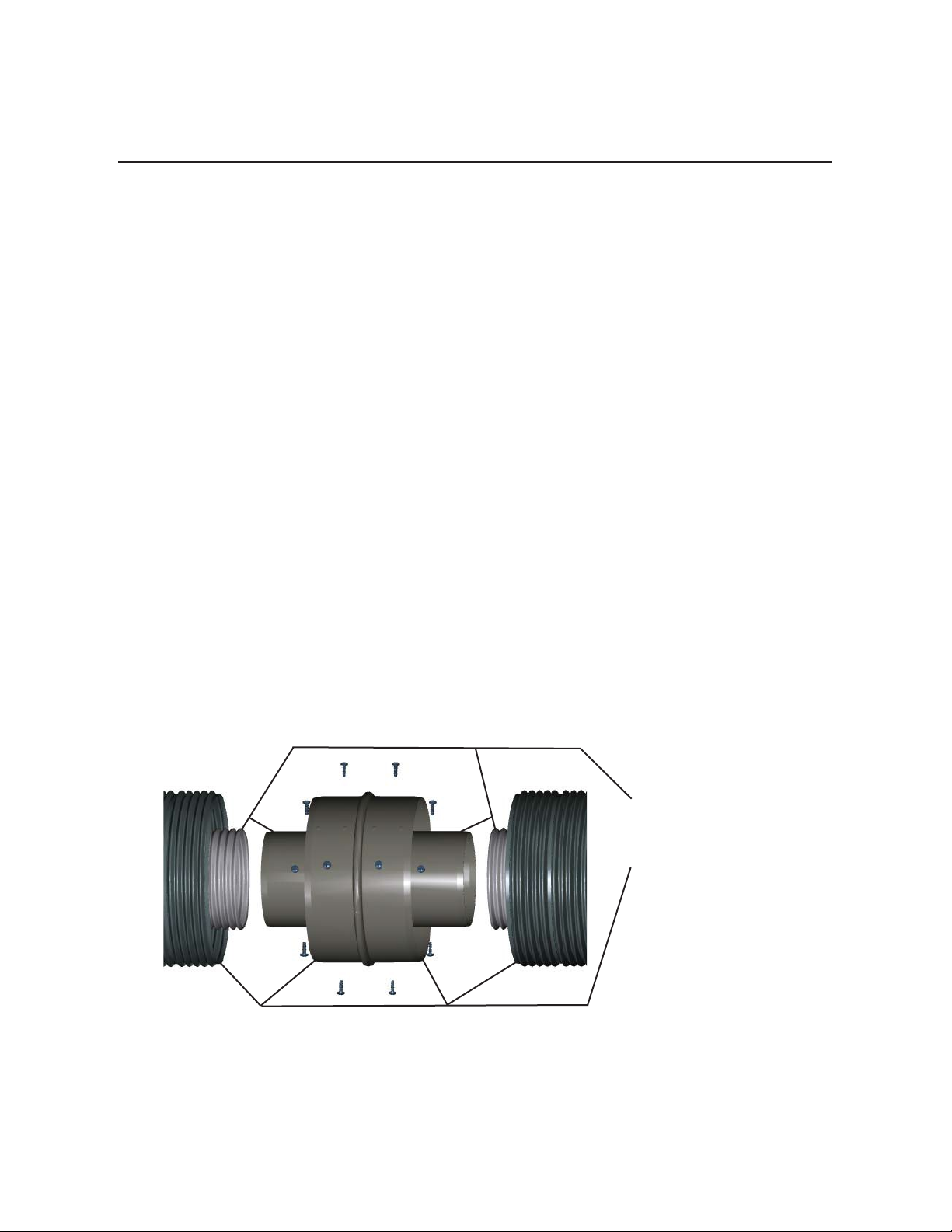
COAXIAL FLEXIBLE COUPLING
a. ONLY IF NECESSARY a single Z-Flex coaxial flexible coupling is allowed to join 2
coaxial flexible vents.
b. Join inner flexible pipes to each end of coaxial flexible coupling inner collars with
a heavy bead approximately 1/4" wide of high temperature Mill-Pac Black sealant
applied approximately 3/4" from end of each flexible coupling inner collar outside
edge and evenly slip inner flexible pipes over flexible coupling inner collars with as
much overlap as possible. Secure inner flexible pipes to flexible coupling inner
collars with four self-drilling screws evenly spaced 90 degrees apart for each
flexible pipe.
c. Join outer flexible pipes to each end of coaxial flexible coupling outer collars with
a heavy bead approximately 1/4" wide of high temperature Mill-Pac Black sealant
applied approximately 3/4" from end of each flexible coupling outer collar outside
edge and evenly slip outer flexible pipes over flexible coupling outer collars with
as much overlap as possible. Secure outer flexible pipes to flexible coupling outer
collars with four self-drilling screws evenly spaced 90 degrees apart for each
flexible pipe.
d. Add coaxial flexible support directly below coaxial flexible coupling.
e. Z-Flex coaxial flexible couplings; part numbers: 2DVK(305,306,406,407,4.507.5,507,
508,608,710,811)C are sold separately.
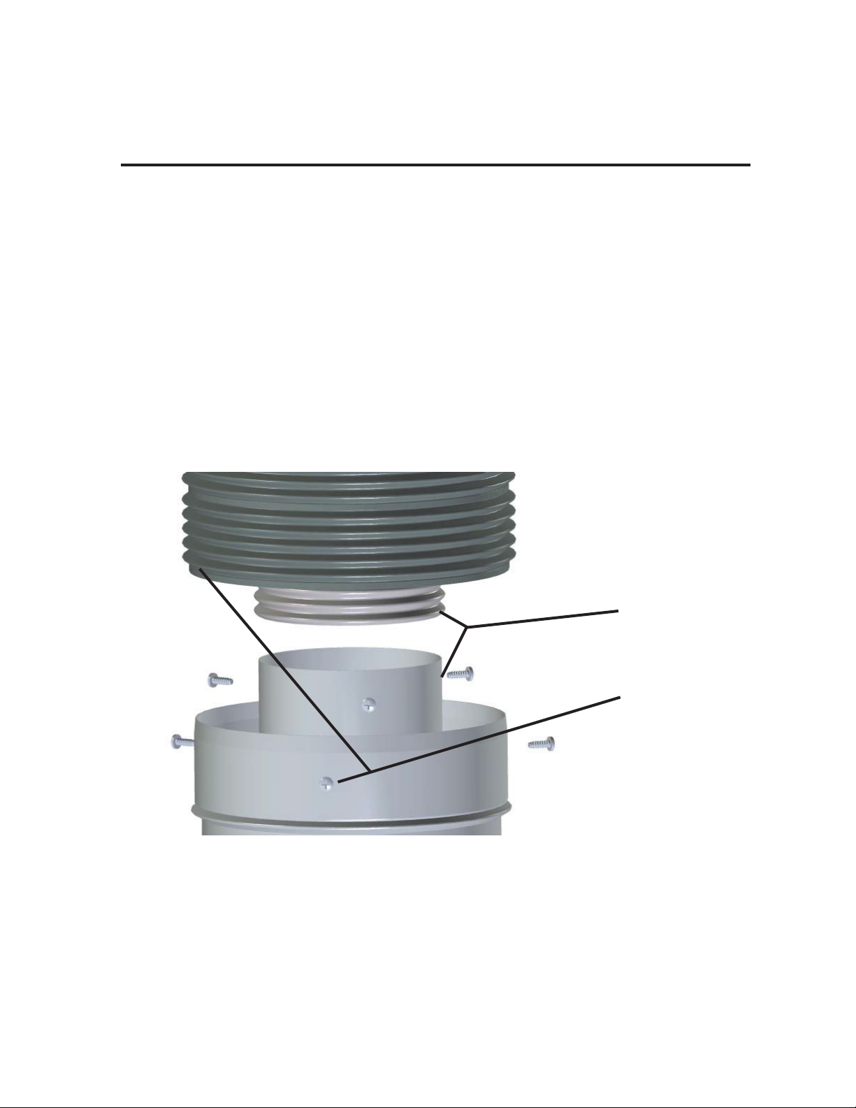
Apply Mill-Pac Black Sealant
& Secure with Screws:
Appliance Inner Male Collars
to Inner Flexible Pipes
& then
Appliance Outlet Male Collars
to Outer Flexible Pipes
Fig. 1 Installation of Z-Flex Coaxial Flexible Coupling
7
Installation Procedure
Z-FLEX
COAXIAL FLEXIBLE VENT
a. Coaxial flexible vent diameters must not be sized less than that specified in the
appliance manufacturer's installation instructions.
b. Prior to installing any flexible pipes extend pipes to their maximum length (see
figure 2 for proper stretching techniques).
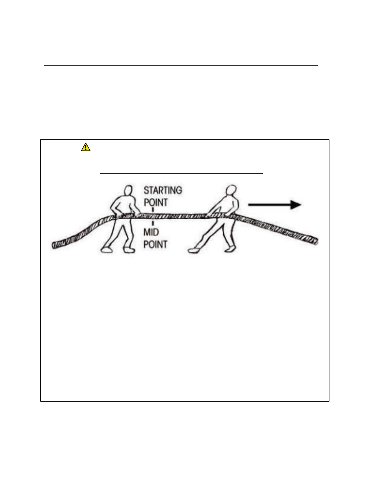
Fig. 2 Proper Stretching Technique for Flexible Pipes
CAUTION
Risk of Injury! Risk of Damage!
Follow these instructions carefully to prevent personal injury and damage to flexible pipes.
PROPER STRETCHING TECHNIQUE FOR FLEXIBLE PIPES
The enclosed flexible pipes are in a fully compressed form.
The stretching of the flexible pipes requires two people
wearing gloves.
A flexible pipe should be stretched working half the length at a time.
Start by facing each other at the appropriate mid-point in the flexible pipe.
Holding the flexible pipe firmly in your hands one person
should walk backwards,
stretching portions of the pipe as they backup.
As you stretch the flexible pipe, watch the corrugations to make
sure you are expanding
the pipe fully as well as not over
-stretching it.
Follow the same procedure for the other half of the flexible pipe.
The flexible pipe should now be at full length.
Repeat above for other flexible pipe.
If you have any questions contact Z-Flex or appliance manufacturer.

8
Installation Procedure
Z-FLEX
COAXIAL FLEXIBLE SPACERS
a. Install coaxial flexible spacers included in kit(s) around extended/stretched
inner (smaller diameter) flexible pipe at every foot maximum, rotate each
WIRE spacer 1/4 turn from previous installed spacer (if supplied intertwine
ends of alternate SPRING spacer).
b. Slide outer extended/stretched flexible pipe over inner flexible pipe with
spacers exercising care not to dislodge any spacers.
c. Additional coaxial flexible spacers; part numbers: 2DVK(35,36,46,47,
57,58,68,710,811)S are sold separately in kits of 10. Use 2DVK58S for
4.5"/7.5" coaxial diameters.
Install Coaxial Flexible
Spacers Around Inner
Flexible Pipe, Rotate Each
WIRE Spacer ¼ Turn From
Previous Installed Spacer
Slide Outer Flexible Pipe
Over Inner Flexible Pipe
With Coaxial Flexible
Spacers
1’ Max.
Between
Coaxial
Flexible
Spacers
Fig. 3 Coaxial Flexible Spacer Installation
9
Installation Procedure
Z-FLEX
APPLIANCE COAXIAL COLLAR
4. Apply a heavy bead approximately 1/4" wide of high temperature Mill-Pac Black
sealant to approximately 3/4" from male end of appliance inner collar outside edge
and slip inner flexible pipe over appliance inner collar with as much overlap as
possible. Secure inner flexible pipe to appliance inner collar with four self-drilling
screws evenly spaced 90 degrees apart.
5. Apply a heavy bead approximately 1/4" wide of high temperature Mill-Pac Black
sealant to approximately 3/4" from male end of appliance outer collar outside edge
and slip outer flexible pipe over appliance outer collar with as much overlap as
possible. Secure outer flexible pipe to appliance outer collar with four self-drilling
screws evenly spaced 90 degrees apart.
Apply Mill-Pac
Black Sealant &
Secure with
Screws
:
Appliance Inner
Male Collar to
Inner Flexible Pipe
& then
Appliance Outer
Male Collar to
Outer Flexible Pipe
Fig. 4 Appliance Coaxial Collar Installation

10
Installation Procedure
Z-FLEX
DV TO COAXIAL FLEXIBLE ADAPTOR - OPTIONAL
a. This adaptor is used to adapt an appliance with Duravent coaxial rigid twist lock
vent connection to coaxial flexible vent. The adaptor's appliance connection has
an inner male collar and outer female collar. The adaptor's flexible vent
connection has an inner male collar and outer male collar. The adaptor part
numbers are 2DVK407A or 2DVK508A & are sold separately.
b. On adaptor's appliance connection with inner male collar and outer female collar,
apply a heavy bead approximately 1/4" wide of high temperature Mill-Pac Black
sealant to approximately 3/4" from inner male collar outside edge.
c. On adaptor's appliance connection with inner male collar and outer female collar,
apply a heavy bead approximately 1/4" wide of high temperature Mill-Pac Black
sealant to approximately 3/4" from outer female collar inside edge.
d. Slip adaptor's appliance connection into/over appliance inner and outer collars
with as much overlap as possible. Secure outer collars with four self-drilling
screws evenly spaced 90 degrees apart.
e. On adaptor's flexible vent connection with inner and outer male collars, apply a
heavy bead approximately 1/4" wide of high temperature Mill-Pac Black sealant
to approximately 3/4" from male inner collar outside edge and slip inner flexible
pipe over inner collar with as much overlap as possible. Secure inner flexible pipe
to inner collar with four self-drilling screws evenly spaced 90 degrees apart.
f. On adaptor's flexible vent connection with inner and outer male collars, apply a
heavy bead approximately 1/4" wide of high temperature Mill-Pac Black sealant
to approximately 3/4" from male outer collar outside edge and slip outer flexible
pipe over outer collar with as much overlap as possible. Secure outer flexible
pipe to outer collar with four self-drilling screws evenly spaced 90 degrees apart.
Apply Mill-Pac Black Sealant
& Secure with Screws:
Inner Male Collar to Inner
Flexible Pipe
& then
Outer Male Collar to Outer
Flexible Pipe
Apply Mill-Pac Black Sealant:
Inner Male Collar Outside Edge &
Outer Female Collar Inside Edge
Secure with Screws
through
Outer Collars
Flexible Vent
Connection
DV to Coaxial
Flexible Adaptor
Appliance Connection
Appliance Twist
Lock Connection
Fig. 5 DV to Coaxial Flexible Adaptor Installation
11
Installation Procedure
Z-FLEX
6. Slope all horizontal runs up and away from appliance with no sags or dips; a minimum
of 1/4" vertical rise per 1 foot of horizontal run.
BEST PRACTICE
For optimum performance; slope all horizontal runs up and away from appliance
with no sags or dips; 1" vertical rise per 1 foot of horizontal run.
COAXIAL FLEXIBLE SUPPORTS
a. Install coaxial flexible supports included in kit every 2 feet maximum for horizontal
runs and every 3 feet maximum for vertical runs and top of each elbow/bend or
according to appliance manufacturer's installation instructions to maintain
appliance manufacturer's clearance to combustibles.
b. Additional coaxial flexible supports; part numbers: 2DVK(05,06,07,07.5,08,10,11)SUP
are sold separately in kits of 5.
Secure Coaxial
Flexible Support to
Building Using
Field Supplied
Hardware
Coaxial Flexible Support:
Every 2 Feet Maximum for
Horizontal Runs
Every 3 Feet Maximum for
Vertical Runs
Top of Each Elbow/Bend
Secure Coaxial
Flexible Support
to Coaxial Flexible
Vent with Bolt &
Nut
Fig. 6 Coaxial Flexible Support Installation
WARNING
Risk of Fire! Risk of Explosion! Risk of Asphyxiation!
Do not slope horizontal runs downward which can lead to poor draft and excessive
temperatures.

12
Installation Procedure
Z-FLEX
7. Using snips or utility knife trim the flexible pipes to the required length.
HORIZONTAL INSTALLATION
8. Use wall thimble(s) when coaxial flexible vent passes through any combustible walls
according to appliance manufacturer's installation instructions.
WALL THIMBLE for Horizontal Combustible Wall
a. Locate center of coaxial flexible vent on wall and mark Inside Opening around
center mark - see Table 1.
Table 1. Combustible Wall Inside Opening MINIMUM for Wall Thimble
b. Cut opening, frame wall & sheet rock to accept wall thimble.
c. Wall thimble is adjustable/telescopic and accommodates wall thickness of 4" to 7".
d. Wall thimble extended is adjustable/telescopic and accommodates
wall thickness of 6" to 11".
e. Separate two halves of thimble and secure to wall with screws from both sides
ensuring each end of thimble overlaps in middle (telescopic).
f. Seal around outer flexible pipe/thimble and wall/thimble with field supplied
sealant. If horizontal fire stop is necessary, discuss sealant and assembly with
fire stop professional and local building and fire officials to ensure assembly
meets with local fire stopping code requirements.
g. Wall thimble; part numbers: 2DVK(05,06,07,07.5,08,10,11)WT, Wall thimble extended;
part numbers: 2DVK(05,06,07,07.5,08,10,11)WTE and Mill-Pac Black sealant; part
number: 2DVKS are sold separately.
WARNING
Risk of Fire!
Review appliance manufacturer's instructions and verify above clearances in
Table 1 are appropriate as it may be necessary to increase
Combustible
Wall Inside Opening MINIMUM for additional clearance.

13
Installation Procedure
Z-FLEX
Secure Wall Thimble to
Building Using Field
Supplied Hardware
Wall Thimble:
Seal Around All Openings
& Wall Thimble with
Field Supplied Sealant
Fig. 7 Wall Thimble Installation - Sold Separately
9. Use siding standoff when flexible pipes pass through and terminate on exterior side
wall with vinyl or wood siding.
SIDING STANDOFF for Horizontal Termination
a. Install siding standoff between exterior wall and coaxial horizontal termination.
b. Secure and seal siding standoff to wall with field supplied screws and sealant.
c. Siding standoffs; part numbers: 2DVK(05,06,07,07.5,08,10,11)SS are sold separately.
10.
11.
12.
13.
Properly orient Horizontal Termination with "UP" stamp on termination.
Apply a heavy bead approximately 1/4" wide of high temperature Mill-Pac Black
sealant to approximately 3/4" from male end of Horizontal Termination inner collar
outside edge and slip inner flexible pipe over horizontal termination inner collar with
as much overlap as possible. Secure inner flexible pipe to inner collar with four self-
drilling screws evenly spaced 90 degrees apart.
Apply a heavy bead approximately 1/4" wide of high temperature Mill-Pac Black
sealant to approximately 3/4" from male end of Horizontal Termination outer collar
outside edge and slip outer flexible pipe over horizontal termination outer collar
with as much overlap as possible. Secure outer flexible pipe to outer collar with four
self-drilling screws evenly spaced 90 degrees apart.
Secure Horizontal Termination to the wall or standoff, ensure "UP" stamp on
termination is properly oriented. Seal around termination where it comes in contact
with wall or standoff with field supplied sealant and paint if required.
WARNING
Risk of Fire! Risk of Explosion! Risk of Asphyxiation!
Coaxial vent/air termination must not be installed recessed into a wall or siding.

14
Installation Procedure
Z-FLEX
Horizontal
Round
Termination
Included in
2DVK-HR
Kits
Wall Thimble -
Sold Separately
Consult
Appliance
Manufacturer’s
Instructions
OR
Siding Standoff -
Sold Separately
Consult
Appliance
Manufacturer’s
Instructions
Horizontal
Square
Termination
Included in
2DVK-HT
Kits
Fig. 8 Wall Thimble, Siding Standoff & Horizontal Terminations
15
Installation Procedure
Z-FLEX
VERTICAL INSTALLATION
14.
15.
Use firestop(s) when coaxial flexible vent passes through any combustible floors or
ceilings without insulation.
Use fire stop/insulation shield kit(s) with insulation collar when coaxial flexible vent
passes through any combustible floors or ceilings with insulation.
FIRE STOP - Vertical
a. Locate center of coaxial flexible vent on floor or ceiling and mark Inside Opening
around center mark - see Table 2.
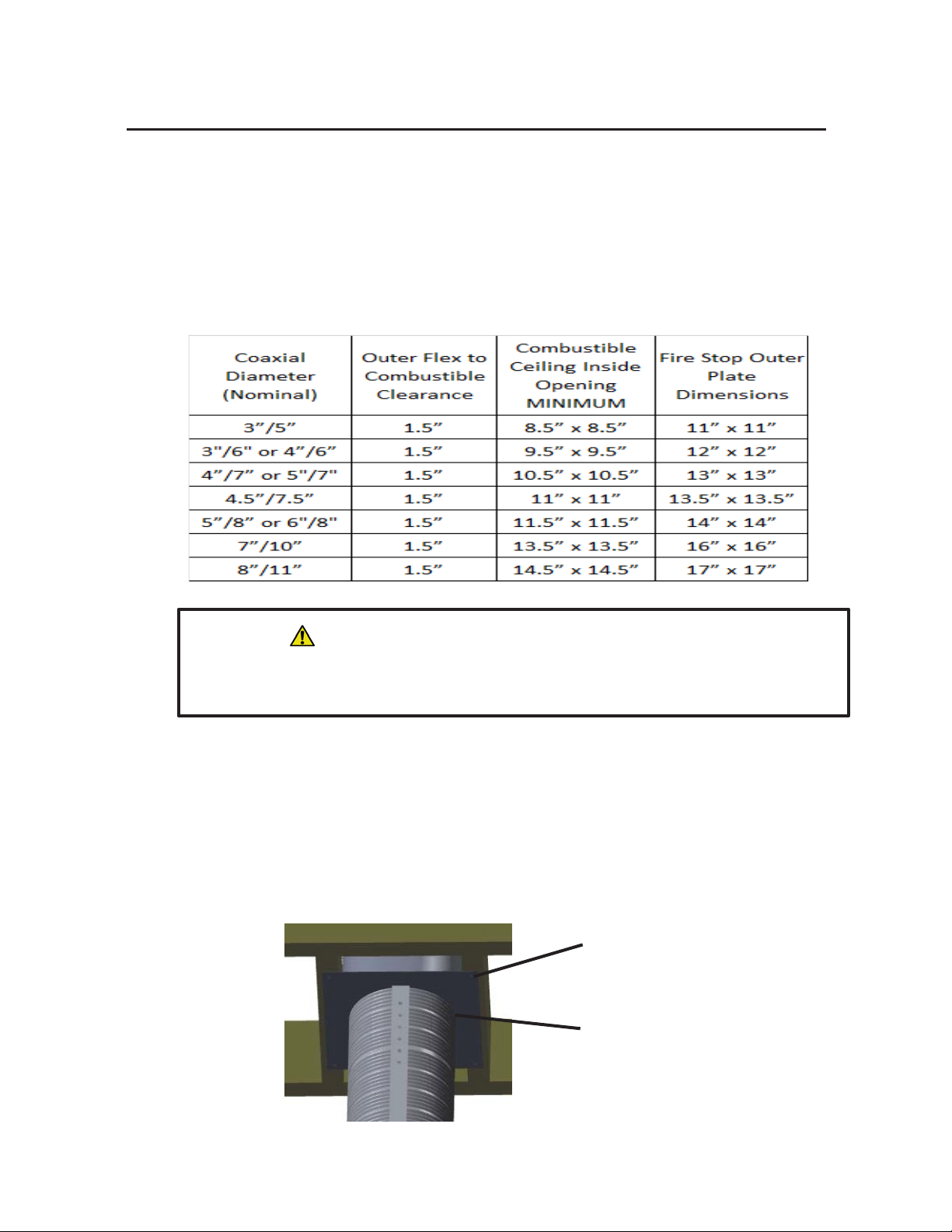
Table 2. Combustible Ceiling Inside Opening MINIMUM for Fire Stop
b. Cut opening, frame floor joists or ceiling & sheet rock to accept fire stop. AVOID
cutting joists by offsetting coaxial flexible vent.
c. Install fire stop on ceiling (bottom side of ceiling or floor joists) and secure with
screws.
d. Seal around outer flexible pipe/fire stop and fire stop/ceiling/joists with field supplied
fire stop sealant. Discuss sealant and assembly with fire stop professional and local
building and fire officials to ensure fire stop meets with local code requirements.
e. Fire stops; part numbers: 2DVK(05,06,07,07.5,08,10,11)FS are sold separately.
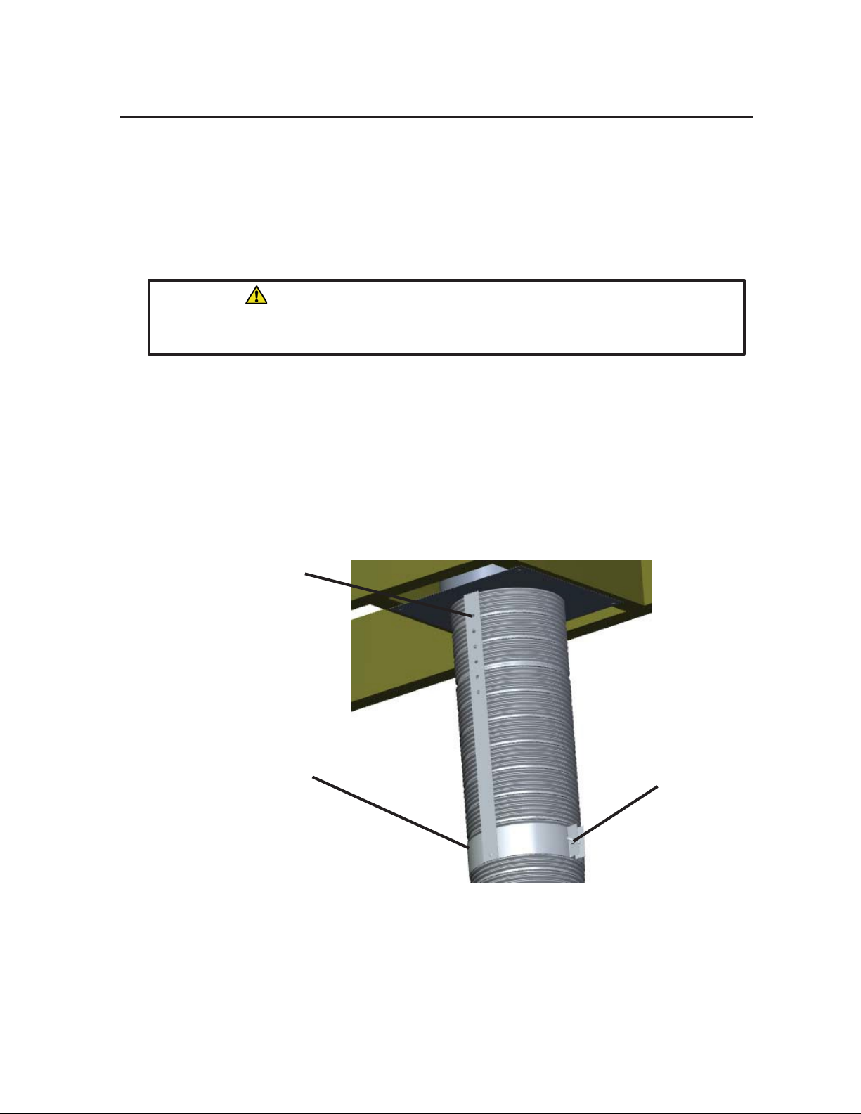
Secure Fire Stop to
Building Using Field
Supplied Hardware
Fire Stop:
Seal Around All Openings
& Fire Stop with Field
Supplied Fire Stop Sealant
Fig. 9 Fire Stop Installation
WARNING
Risk of Fire!
Review appliance manufacturer's instructions and verify above clearance in Table 2
is appropriate as it may be necessary to increase Combustible
Ceiling Inside
Opening MINIMUM for additional clearance.
16
Installation Procedure
Z-FLEX
FIRE STOP/INSULATION SHIELD KIT with INSULATION COLLAR
a. Fire stop/insulation shield kit with insulation collar prevents insulation from
coming in contact with flexible pipes when passing through any combustible
floor or ceiling.
b. Fire stop/insulation shield is 18" tall and the height of its insulation shield
(pipe) can be cut down provided installed height of shield is above insulation.
c. Locate center of coaxial pipe on floor or ceiling and mark appropriate opening
(inside dimensions) around center mark - see Table 2.
d. Cut opening and frame floor joists or ceiling to accept fire stop. AVOID cutting
joists by offsetting coaxial flexible pipe.
e. Install fire stop on ceiling (bottom side of ceiling or floor joists) and secure with
screws.
f. Seal around outer flexible pipe/fire stop/insulation shield and fire stop/
insulation shield/ceiling/joists with field supplied fire stop sealant. Discuss
sealant and assembly with fire stop professional and local building and fire
officials to ensure fire stop meets with local code requirements.
g. Cover top of fire stop/insulation shield (pipe) with insulation collar included in
kit; slide insulation collar with flared end down, over and down coaxial pipes
until it is just above top of fire stop/insulation shield (pipe).
h. Secure insulation collar to coaxial flexible pipe with gear clamp.
i. A fire stop/insulation shield kit: part number: 2DVK(05,06,07,07.5,08,10,11)FSIS
is included in the vertical kit additional kits are sold separately.
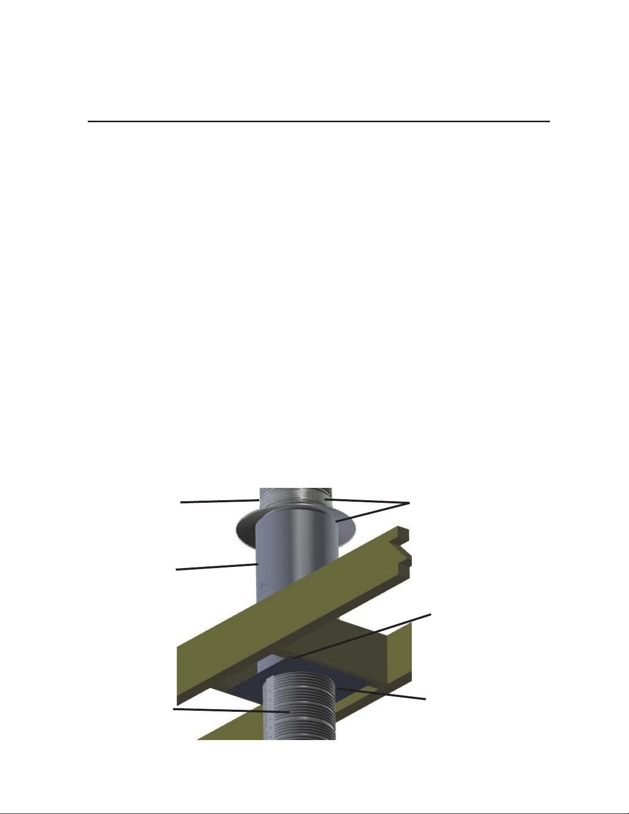
Insulation
Collar
Insulation
Shield:
Installed
Height
Must Be
Above
Insulation
Cover Top of Insulation
Shield with Insulation Collar
& Secure to Coaxial Flexible
Vent with Gear Clamp
Secure Fire Stop to
Building Using Field
Supplied Hardware
Coaxial
Flexible
Vent
Fire Stop:
Seal Around All Openings
& Fire Stop with Field
Supplied Fire Stop Sealant
Fig. 10 Fire Stop/Insulation Shield Kit Installation
17
Installation Procedure
Z-FLEX
16. Enclose coaxial vertical pipes in any occupied areas above first floor, including closets
and storage spaces. The enclosure needs to support and maintain minimum
clearances to coaxial pipes/vent and may be framed and sheet rocked.
17. Locate and mark center of coaxial pipe on roof.
18. Review appliance manufacturer's installation instructions for clearances of vent to
combustible surfaces and cut appropriate sized hole in roof incorporating necessary
clearances.
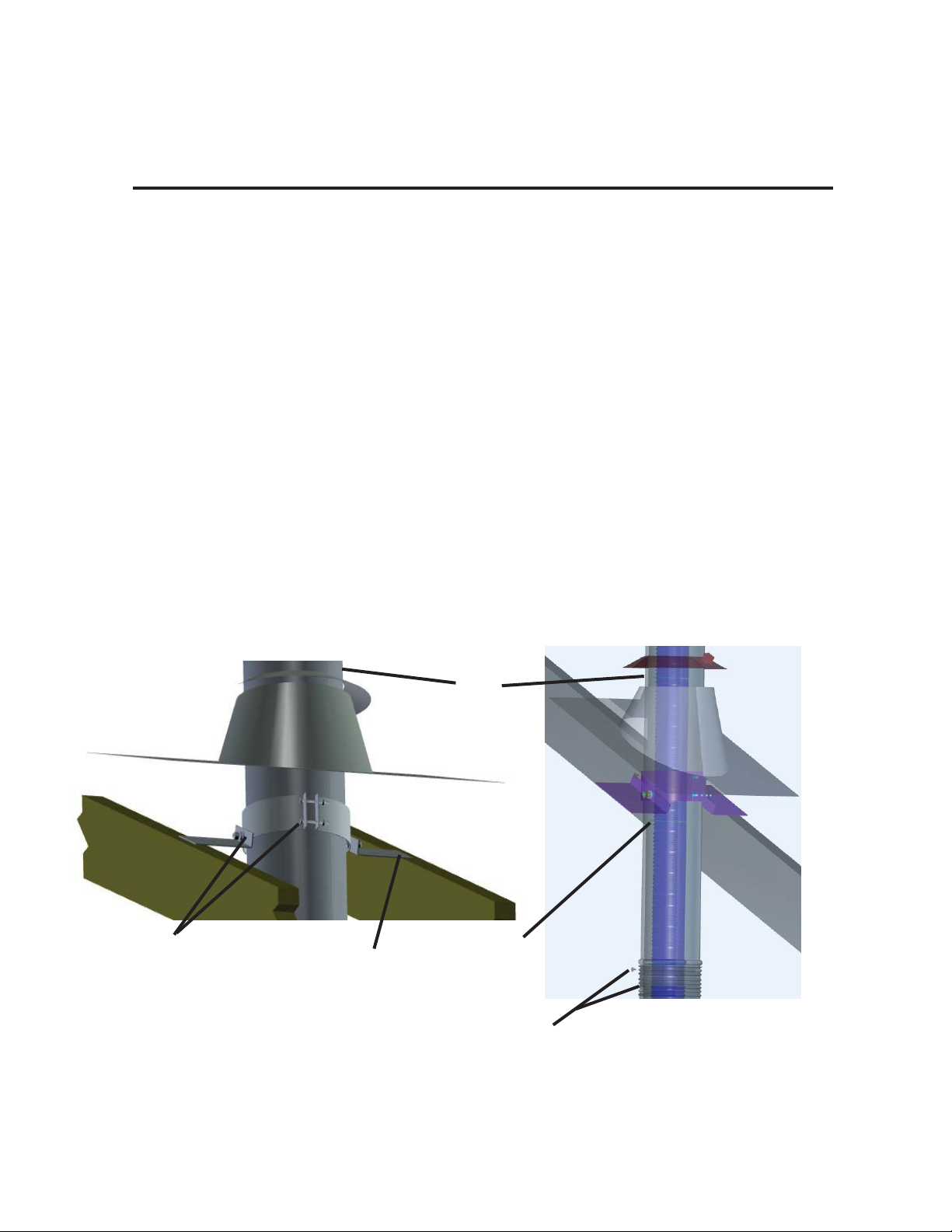
ROOF TERMINATION SUPPORT
a. Center roof support over hole in roof and secure to top of roof.
b. Install 42" long rigid pipe included in vertical kit through roof support and tighten
roof support around outer rigid pipe and with provided 1/2" long screws ensuring
pipe is vertically plumb and extends below roofline approximately 1 foot below
lowest opening in roof or enough to facilitate connection to outer flexible pipe.
c. Inner flue pipe provided in 2DVK-VX kits are 48" longer than outer pipe and
include 4 additional coaxial flexible spacers.
d. Install spacers every foot on inner flue pipe and route inner flue pipe through 42"
long rigid pipe yielding a coaxial assembly.
Rigid
Pipe
Secure Roof
Termination
Support to
Rigid Pipe
with Bolts/
Nuts & 3
Self-drilling
Screws
Secure Roof
Termination
Support to Top
of Roof Using
Field Supplied
Hardware
Route Inner
Flexible Pipe
with Coaxial
Flexible
Spacers
Through
Rigid Pipe
Apply Mill-Pac Black Sealant &
Secure with Screws:
Outer Rigid Pipe to Outer Flexible Pipe
Fig. 11 Roof Termination Support Installation
18
Installation Procedure
Z-FLEX
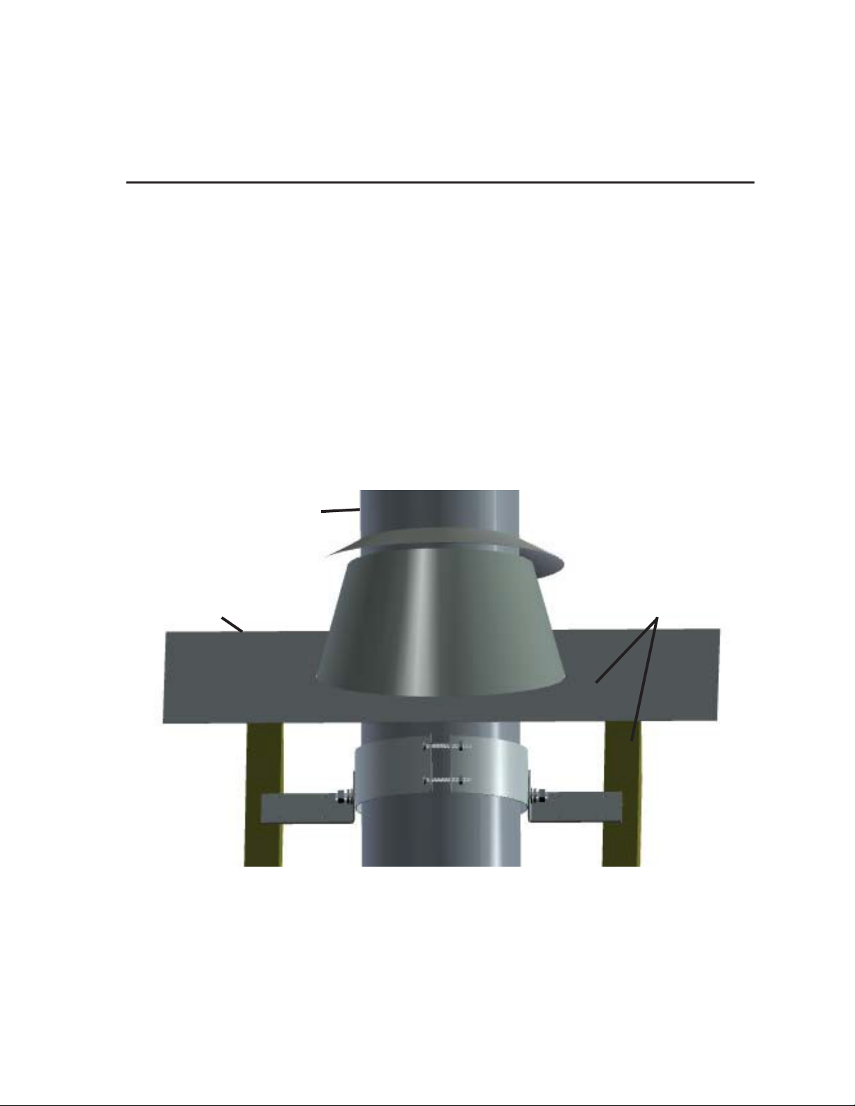
ROOF FLASHING
a. The roof flashing provided in vertical kit is for roofs with pitch of 0 to 30
degrees (0/12 to 7/12 pitch).
b. Optional flashings; part numbers: 2DVK(05,06,07,0.75,08,10,11)F are available
for roofs with larger pitch of 30 to 45 degrees (7/12 to 12/12 pitch) and are
sold separately.
c. Check roof pitch and ensure proper flashing is installed.
d. On top of roof, slide flashing with appropriate pitch over rigid pipe.
e. Slip upper half of roof flashing plate under roof shingles while lower half of
flashing plate rests on top of roof shingles.
f. Seal roof flashing to roof with a suitable field supplied waterproof mastic.
g. Secure roof flashing to roof using field supplied roofing nails and neoprene
washers or suitable waterproof mastic to cover nail heads.
Fig. 12 Roof Flashing Installation
19.
20.
Review appliance manufacturer's installation instructions and local codes to
determine required installation height of termination above highest point of roof.
Add rigid extension pipe to top of rigid pipe protruding through roof as necessary
to meet required installation height of termination above roof.
Rigid Pipe
Roof Flashing Plate:
Slip Upper Half
Under Roof Shingles
Seal & Secure Roof
Flashing to Roof
Using Field Supplied
Hardware & Sealant
19
Installation Procedure
Z-FLEX
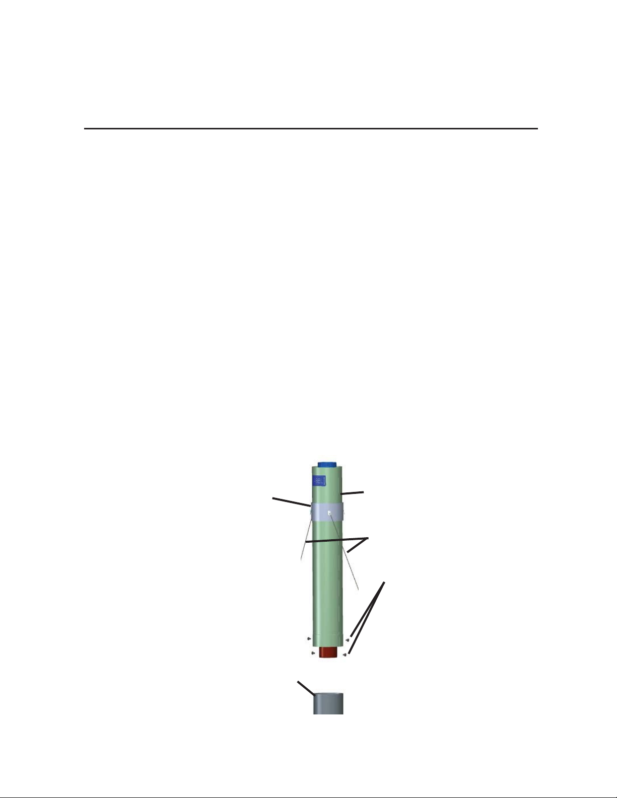
RIGID EXTENSION PIPE - For Extending Height of Vertical Termination
a. A 30 Inch long rigid extension pipe with flexible inner pipe, flexible spacers, male
connector and guy band support; part numbers:
2DVKRE(35,36,46,47,4.57.5,57,58,68,710,811) are sold separately.
b. Cut top of flexible inner pipe just above 42" long rigid pipe as necessary to facilitate
the joint.
c. Apply a heavy bead approximately 1/4" wide of high temperature Mill-Pac Black
sealant to approximately 3/4" from bottom male connector end of rigid extension
pipe inner collar outside edge and slip flexible pipe over collar with as much overlap
as possible. Secure inner pipe to collar with four self-drilling screws evenly spaced 90
degrees apart.
d. Slip rigid extension pipe over rigid pipe with as much overlap as possible. Secure rigid
extension pipe to rigid pipe with four self-drilling screws evenly spaced 90 degrees
apart.
e. Slide guy band support down rigid extension pipe to within 1 foot of vent
termination and secure with #10-24 bolt and nut provided with guy band support.
f. Attached field supplied stainless steel or galvanized cable with a minimum rated
capacity of 500lbs. to each of the four anchor holes.
g. Anchor cables to a rigid building member using an appropriate field supplied
fastening method.
Guy
Band
Support
Rigid Extension Pipe:
30” Long
Field Supplied Cables:
500lbs Rating
Rig
id Pi
pe:
42” Long
Apply Mill-Pac Black
Sealant & Secure with
Screws:
Inner Male Collar to Inner
Flexible Pipe
& then
Outer Rigid Pipes
Fig. 13 Rigid Extension Pipe Installation
20
Installation Procedure
Z-FLEX
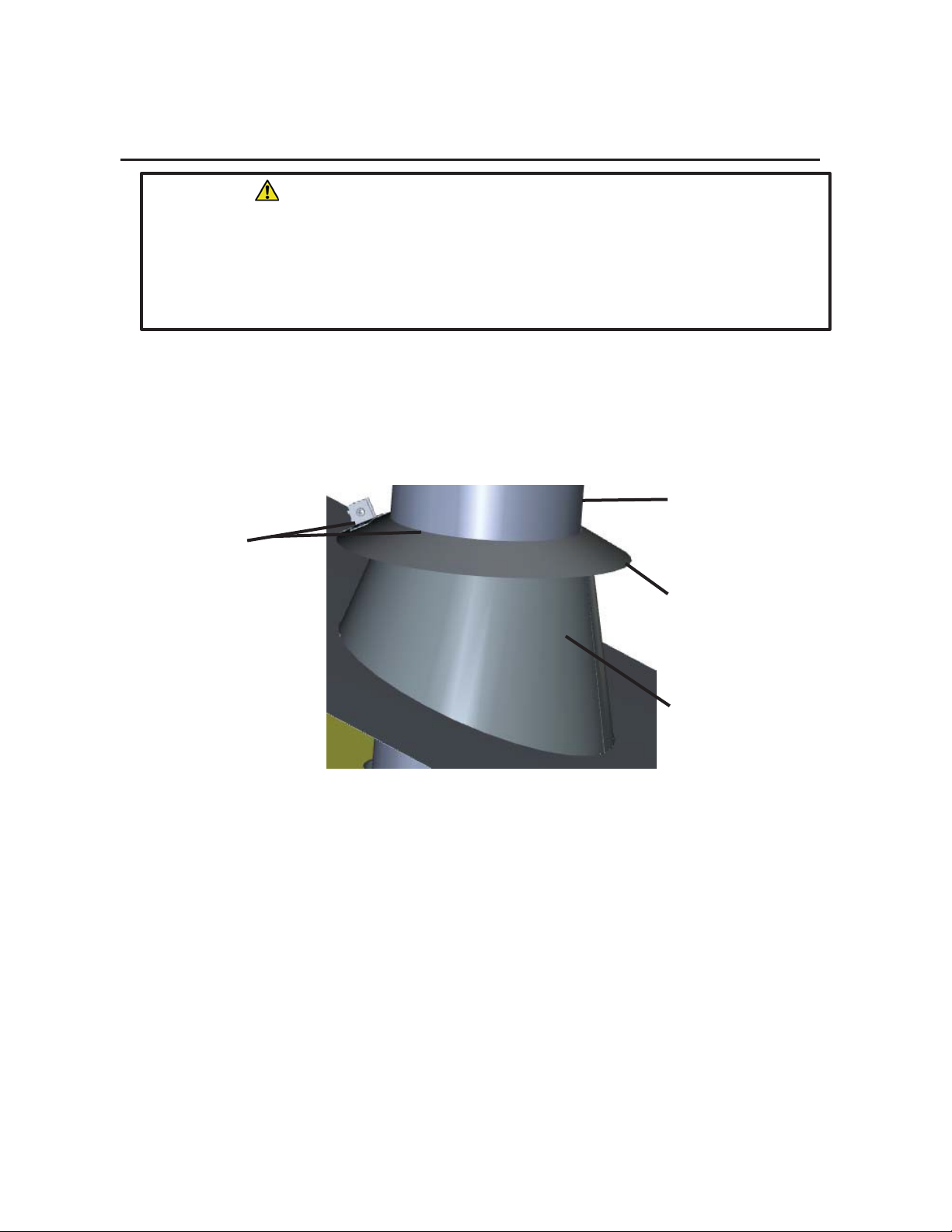
STORM COLLAR/SUPPORT
a. Slide storm collar/support with flared end down, over and down rigid pipe(s)
until it is just above top of roof flashing.
b. Seal/waterproof between inside diameter of storm collar/support and outside
diameter of rigid pipe with high temperature Mill-Pac Black sealant.
c. Secure storm collar/support to rigid pipe with bolt and nut.
Secure Storm
Collar/Support to
Rigid Pipe Just
Above Roof
Flashing & Seal
Between Both
with Sealant
Rigid
Pipe
Storm
Collar/
Support
Roof
Flashing
Fig. 14 Storm Collar/Support Installation
WARNING
Risk of Fire! Risk of Explosion! Risk of Asphyxiation!
High wind conditions, nearby big trees, adjoining roof lines, steep pitched roofs may
cause poor draft or down drafting.
In these cases increasing the installation height of
termination above highest point of roof may solve drafting
problem. Review
appliance manufac
turer's instructions to ensure maximum installed lengths (vertical
and horizontal) are not exceeded.
This manual suits for next models
2
Table of contents
Popular Fireplace Accessories manuals by other brands

Dimplex
Dimplex SMP-175-PE install guide

Lennox Hearth Products
Lennox Hearth Products LSO-43 installation instructions

Outdoor Lifestyles
Outdoor Lifestyles ODCOUG-36SSL installation instructions

FireplaceXtrordinair
FireplaceXtrordinair 564 25K Installation

Valor
Valor L2 SERIES installation manual

Empire Comfort Systems
Empire Comfort Systems EMBC-1S-C-1 Assembly instructions


Town & Country Fireplaces
Town & Country Fireplaces TC42 installation instructions

pleasant hearth
pleasant hearth LS932B manual

O-TL
O-TL System 4 LP Installation and operation guide

CMC
CMC DV ReFace Screen Installation & operation manual

SBI
SBI AC02082 Installation

Heatilator
Heatilator ST-CFL-24NG Log Placement Instructions