NOVAKON X12 Series User manual

User Manual
User Manual
X12 series
12.1" Fanless Multi-touch Panel PC
with Intel® Celeron® J1900 Processor
User Manual
Record of Revision
Version
Issued Date
Description
Author
v0.1
2016.5.6
First Release
Jason

User Manual
Acknowledgements
Intel and Pentium are trademarks of Intel Corporation.
Microsoft Windows and MS-DOS are registered trademarks of Microsoft Corp.
All other product names or trademarks are properties of their respective owners.
Safety Instructions
1. Read these safety instructions carefully.
2. Keep this User Manual for later reference.
3. Disconnect this equipment from any AC outlet before cleaning. Use a damp cloth. Do
not use liquid or spray detergents for cleaning.
4. For plug-in equipment, the power outlet socket must be located near the equipment
and must be easily accessible.
5. Keep this equipment away from humidity.
6. Put this equipment on a reliable surface during installation. Dropping it or letting it fall
may cause damage.
7. The openings on the enclosure are for air convection. Protect the equipment from
overheating. DO NOT COVER THE OPENINGS.
8. Make sure the voltage of the power source is correct before connecting the equipment
to the power outlet.
9. Position the power cord so that people cannot step on it. Do not place anything over
the power cord.
10. All cautions and warnings on the equipment should be noted.
11. If the equipment is not used for a long time, disconnect it from the power source to
avoid damage by transient overvoltage.
12. Never pour any liquid into an opening. This may cause fire or electrical shock.
13. Never open the equipment. For safety reasons, the equipment should be opened only
by qualified service personnel.
➢If one of the following situations arises, get the equipment checked by service
personnel:
➢The power cord or plug is damaged.
➢Liquid has penetrated into the equipment.
➢The equipment has been exposed to moisture.
➢The equipment does not work well, or you cannot get it to work according to
the user's manual.

User Manual
➢The equipment has been dropped and damaged.
➢The equipment has obvious signs of breakage.
14. DO NOT LEAVE THIS EQUIPMENT IN AN ENVIRONMENT WHERE THESTORAGE
TEMPERATURE MAY GO BELOW -20° C (-4° F) OR ABOVE 60° C(140° F). THIS COULD
DAMAGE THE EQUIPMENT. THE EQUIPMENT SHOULD BE IN A CONTROLLED
ENVIRONMENT.
15. CAUTION: DANGER OF EXPLOSION IF BATTERY IS INCORRECTLY REPLACED. REPLACE
ONLY WITH THE SAME OR EQUIVALENT TYPE RECOMMENDED BY THE MANUFACTURER,
DISCARD USED BATTERIES ACCORDING TO THE MANUFACTURER'S INSTRUCTIONS.
Safety Precaution - Static Electricity
Follow these simple precautions to protect yourself from harm and the products from
damage.
➢To avoid electrical shock, always disconnect the power from your PC chassis
before you work on it. Don't touch any components on the CPU card or other
cards while the PC is on.
➢Disconnect power before making any configuration changes. The sudden rush
of power as you connect a jumper or install a card may damage sensitive electronic
components.

User Manual
Contents
Chapter 1: General Introduction...................................................................1
1.1 Overview............................................................... ......................1
1.2 Key Features................................................................................................3
1.3 Hardware Specification...............................................................3
1.4 I/O Arrangement........................................................................5
1.5 Mechanical Dimension.................................................................................10
Chapter 2: VESA / Panel Mounting.........................................................12
2.1 VESA Mounting............................................................................12
2.2 Panel Mounting............................................................................12
Chapter 3: System Setup ...................................................................13
3.1 Power Installation Procedure.......................................................13
3.2 Installing 2.5" HDD .........................................................................14
3.3 Resistive Touch Setting.....................................................................16
Chapter 4: BIOS Setting.......................................................................19
4.1 Main............................................................................................20
4.2 Advanced.....................................................................................21
4.2.1 CPU Configuration................................................................22
4.2.2 Chipset Configuration...........................................................23
4.2.3 Storage Configuration............................................................24
4.2.4 Intel(R) Smart Connect Technology................................ .......25
4.2.5 Super IO Configuration..........................................................26
4.2.6 ACPI Configuration.................................................................27
4.2.7 USB Configuration.................................................................28
4.2.8 Instant Flash.......................................................................... 29
4.3 H/W Monitor...............................................................................30
4.4 Security.......................................................................................31
4.5 Boot.............................................................................................32
4.5.1 CSM (Compatibility Support Module)....................................3 3
4.6 Exit.............................................................................................34
Chapter 3: BIOS Setting................................................................17
3.1 Main Menu...........................................................................17
3 . 2 A d v a n c e d M e n u . . . . . . . . . . . . . . . . . . . . . . . . . . . . . . . . . . . . . .
. . . . . . . . . . . . . . . . . . . . . . . . . . . . . . . . 3 4
3.6 Exit Menu..............................................................................35
Page 1
Chapter1. General Introduction
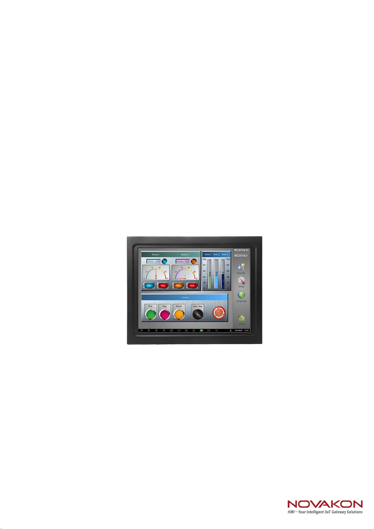
1.1 Overview
Novakon's X12 is a new 12.1" multi-touch Panel PC equipped with an Intel® Celeron®
J1900 processor. The new Bay Trail CPU offers the advantage of desktop performance
with low power consumption. The fanless design increases reliability, and the 7H
surface hardness guarantees superior durability. The X12 also supports two-finger
touch control while wearing gloves. With dual GbE LAN, 4 serial ports, 4 USB ports
and 9-36V DC input, the X12 makes connecting multiple devices easy when
integrating solutions.
(Front Cover)

Page 2
(Back Cover)
(I/O Cover)
Page 3
1.2 Key Features
12.1" XGA LED panel with Projected Capacitive or Resistive touch display
Intel® Celeron® J1900 2.0 GHz Processor
Supports Two-finger Touch Control while Wearing Gloves
System memory up to 8 GB DDR3L 1333 SDRAM
Internal SATA 2.5" HDD and mSATA socket
2 GbE, HD Audio, 4 USB, 4 COM, Mini PCIe, VGA & HDMI
VESA & Panel mounting
1.3 Hardware Specification
Model
X12-P
X12-R
Processor
System
CPU
Intel® Celeron® Processor J1900
Frequency
2.0 GHz / 2.42 GHz (Boost), 4 Cores / 4 Threads
L2 Cache
2 MB
System Chipset
N/A
BIOS
UEFI
Memory
Technology
DDR3L 1333 MHz SDRAM
Max. Capacity
8 GB
Socket
1, 204-pin SO-DIMM
Display
Panel Size
12.1” LED Panel
Resolution
1024 x768 (XGA)
Viewing Angle
80 x 80 (H) x 80 x 80 (V)
Brightness
500(cd/m2)
Color Support
16.2M
Contrast Ratio
700:1
Response Time
35(msec)
VGA
Up to 1920 x 1200
HDMI
HDMI 1.4a up to 1920 x 1200
Dual Display
LCD + VGA or LCD + HDMI
Touch screen
Touch screen Type
Projected Capacitive
5 Wire Resistive
Surface Hardness
7H
3H
Page 4
Durability
10 millions times
Transparency
90%(±3%)
80%(±3%)
I/O Interface
USB
2 USB 3.0, 2 USB 2.0
Serial Port
4 COM ports (3/ RS-232, 1 RS-232/422/485 for COM1)
GPIO(option)
8 Pin GPIO 3.3V (DP-9 Connect)
Ethernet
Controller
Dual GbE, 10/100/1000 Mbps (Realtek RTL8111G-CG)
Audio
Chipset
Realtek ALC662 High Definition Audio (HD)
Connector
Line out
Expansion
Mini PCIe
1 Full-size Mini PCIe or mSATA, selected by jumper setting,
1 Half-size Mini PCIe
Storage
SATA II
1 Internal 2.5” HDD/SSD
mSATA
Supports either mSATA or full-size Mini PCIe, selected by
jumper setting
Power
Power Supply
Voltage
Supports 9-36 V DC input (Phoenix Connector)
Power Adaptor
AC-to-DC, 12 V @ 5 A(60 W) DC-output
Power Input
9-36 V DC-input, 6.6A - 1.6A
Power
Consumption
Typical: 1.45A @ 12V (17.4W) DC-input
Full Load: 1.72A @ 12V (20.7W) DC-input
Environment
Operational Temp
-20~60°C (4~140° F) w/ 2.5” SSD
Non-Operational
-40~80°C (-40~185°F)
Humidity
5~95% @ 40°C, non-condensing
Vibration
5-500 Hz, 0.026 G²/Hz, 2.16 Grms, X, Y, Z, 1 hour per axis
EMC
CE, FCC Class A
General
Dimensions
(L x H x D)
319.6 x 253.6 x 64 mm (12.58” x 9.98” x 2.52”)
Weight
3.30 kg (7.26 lb)
3.26 kg (7.19 lb)
Operating System
Windows 7/8.1, WES7 E/P, WE8S
Front Panel
Waterproof
IP 54

Page 5
1.4 I/O Arrangement
Power Button
Press this button to turn on the system.
(Orange light: Stand By / Blue light : Power On)
DC 9-36V Power Input Connector
This System supports DC 9-36V input power voltage.
This connector must be connected to DC 9 to 36 V power adaptor.
After plugging phoenix connector, be sure to fasten the two screws to lock
the connector.
HDMI Port
This port can be connected to the HDMI monitor.
Notice that users cannot use HDMI and VGA as video output at the same
time, because the "dual display" function is set for HDMI+LCD or VGA+LCD.
VGA Port
This port can be connected to the VGA monitor.
Notice that users cannot use HDMI and VGA as video output at the same
time, because the "dual display" function is set for HDMI+LCD or VGA+LCD.
HDMI Port
LAN Port
GPIO
DC 9-36V Power
Input
USB 2.0 Port
VGA Port
USB 3.0 Port
Power Button
COM2
COM1
COM4
COM3
LINE OUT
Page 6
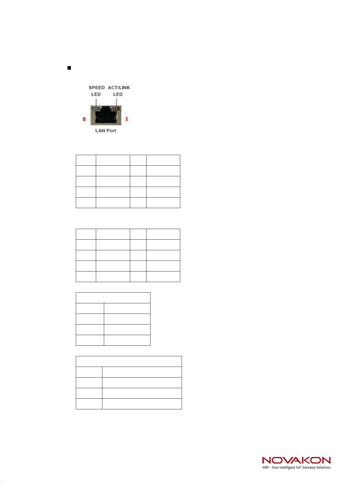
LAN Port
This port can be connected to the Ethernet via RJ-45 connector .
10/100BASE-T:
Pin
Definition
Pin
Definition
1
TX_D0+
5
NC
2
TX_D0-
6
RX_D1-
3
RX_D1+
7
NC
4
NC
8
NC
1000BASE-T:
Pin
Definition
Pin
Definition
1
TX_D0+
5
BI_D2-
2
TX_D0-
6
RX_D1-
3
RX_D1+
7
BI_D3+
4
BI_D2+
8
BI_D3-
Activity/Link LED
Status
Description
Off
No Link
Blinking
Data Activity
On
Link
SPEED LED
Status
Description
Off
10Mbps connection
Green
100Mbps connection
Orange
1Gbps connection
Page 7
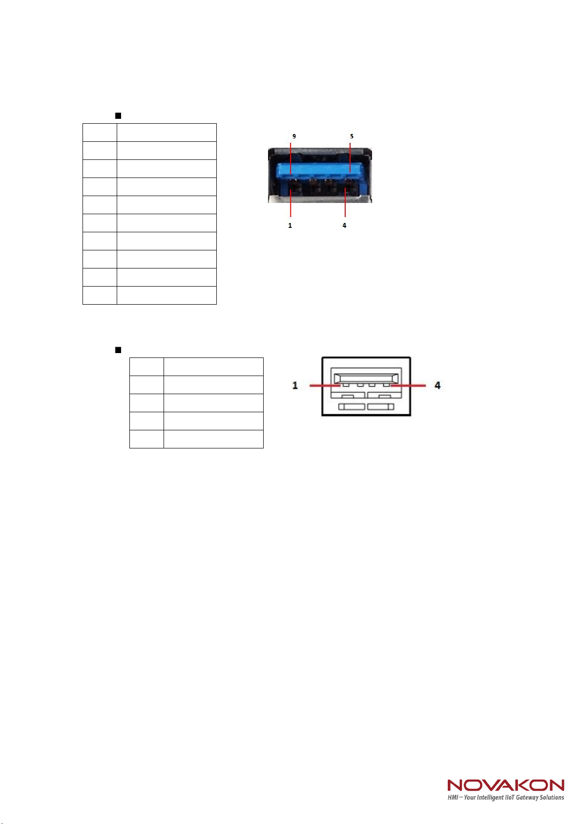
USB 3.0 Port
Each USB3.0 port supports 900mA @ 5 V
USB 2.0 Port
Each USB2.0 port supports 500mA @ 5 V
Pin
Definition
1
+5
2
USB-
3
USB+
4
GND
5
StdA_SSRX-
6
StdA_SSRX+
7
GND_DRAIN
8
StdA_SSTX-
9
StdA_SSTX+
Pin
Definition
1
+5
2
USB-
3
USB+
4
GND
Page 8
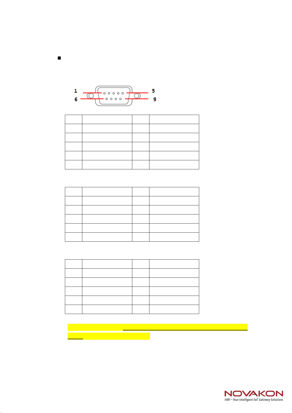
COM 1 Ports (RS-232/422/485)
Users can change the configuration of COM1 by using BIOS setup utility.
Pin
Definition
Pin
Definition
1
DCD
6
DSR
2
RXD
7
RTS
3
TXD
8
CTS
4
DTR
9
RI
5
GND
(RS-232)
Pin
Definition
Pin
Definition
1
TX-
6
N/A
2
RX+
7
N/A
3
TX+
8
N/A
4
RX-
9
N/A
5
GND
(RS-422)
Pin
Definition
Pin
Definition
1
RTX-
6
N/A
2
N/A
7
N/A
3
RTX+
8
N/A
4
N/A
9
N/A
5
GND
(RS-485)
NOTE: Please refer to Chapter4 BIOS Setting - 4.2.5 COM1 Configuration
(page) to set parameters of COM1

Page 9
COM 2-3-4 (RS-232 only)
Pin
Definition
Pin
Definition
1
DCD
6
DSR
2
RXD
7
RTS
3
TXD
8
CTS
4
DTR
9
RI
(RS-232)
GPIO Ports (Option)
Pin
Definition
1
SIO_GP1
2
SIO_GP2
3
SIO_GP3
4
SIO_GP4
5
SIO_GP5
6
SIO_GP6
7
SIO_GP7
8
SIO_GP8
9
VCC(12V default / 5V)
Shielding
GND
Audio Port
Green connector means LINE OUT
Page 10
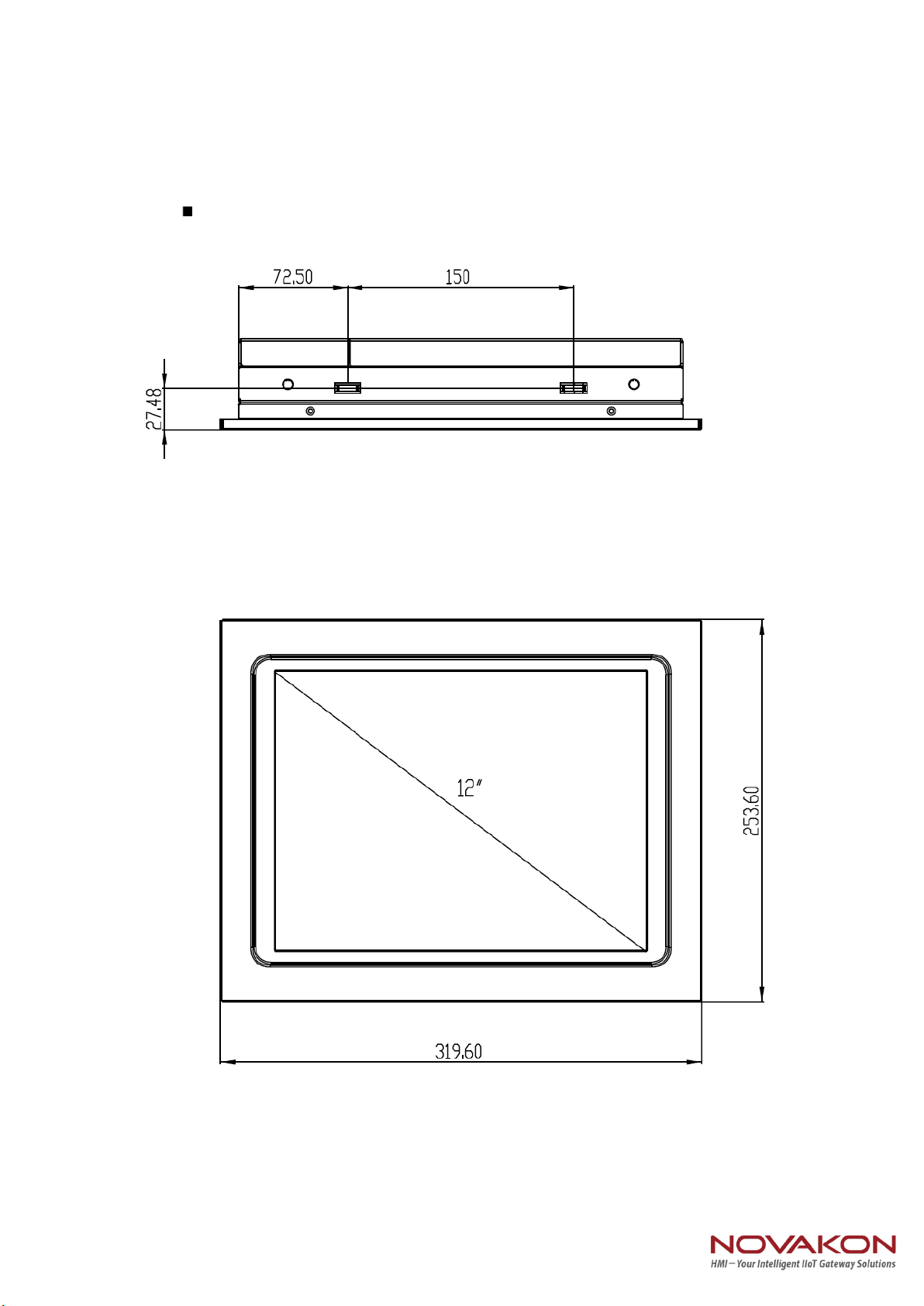
1.5 Mechanical Dimension
Panel PC Dimension

Page 11
Panel PC Dimension (Back side)
Page 12
Chapter 2. VESA Mounting
2.1 VESA Mounting
Step1. Check the VASA mount dimension on the back cover .
There are two choice : 100 x 100mm or 75 x 75 mm
Step2. Fasten the four screws to bond monitor to VESA Stand
Warning !
1. The length of VASA mount screw cannot exceed 5mm.
(Calculated from monitor's back cover)
2. Any wrong installation will cause monitor's great
damage.
3. The Spec of VASA mount screw is M4 size.
2.2 Panel mount
Accessory Kit screw (M4*30) lock wall fasteners. As shown below.
1. Screw Length Limitation: 5mm
(Calculated from monitor's back cover)
2. Screw Spec Limitation: M4 size

Page 13
Chapter3. System Setup
3.1 Power Installation Procedure
Step 1. Connect a power cord to the power adaptor.
AC to DC power adaptor specification
1. Input support voltage: 110V ~ 240V AC power , 50~60Hz
2. Output support voltage: 12V DC power @5A MAX
3. 0~40 degree C operating temperature
Step 2. Connect another male plug of the power cord to an electrical outlet.
Step 3. Connect the Phoenix Connector Terminal into the system's Power Input
Connector.
WARNING:
1. After plugging phoenix connector , be sure to fasten the two
screws to lock the connector.
2. White cable stands for 12V , block cable stand for GND. Make
sure you plug connector in correct direction.
Page 14
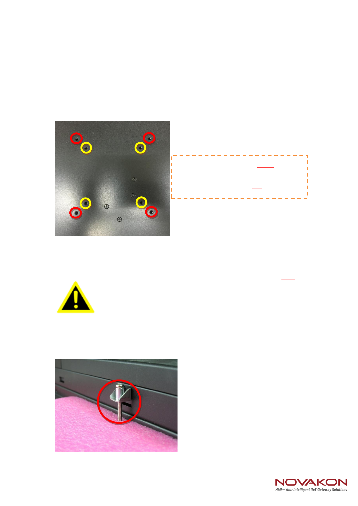
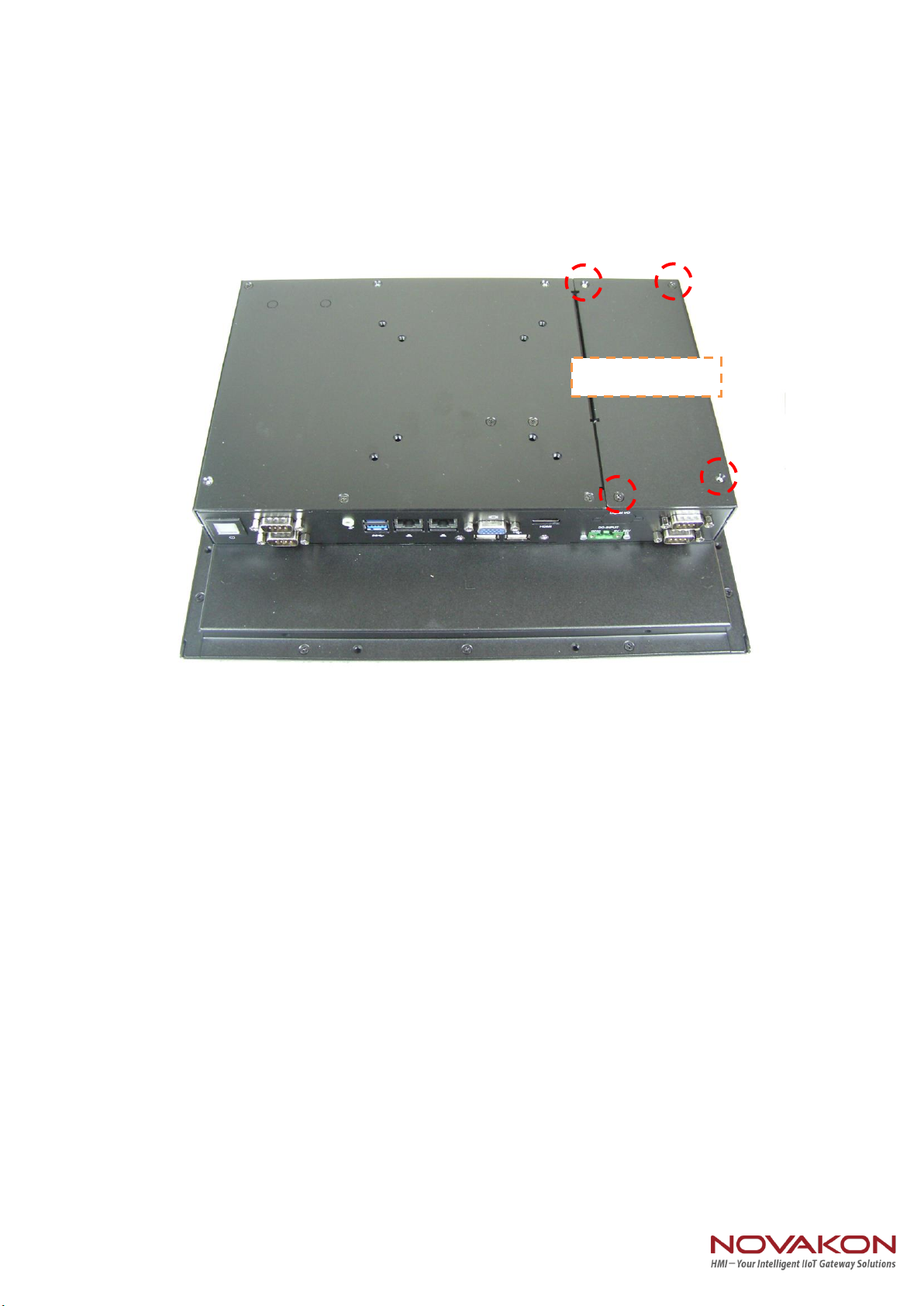
3.2 Installing 2.5" HDD
Step 1. Loosen the 4 screws on the "HDD Back Cover" , and open the cover.
HDD Back Cover
Page 15
Step 2.
(1) You will see a "HDD Bracket" for 2.5" size HDD/SSD(7mm or 9mm thickness).
(2) Pick up the "HDD Bracket", and Loosen/tighten the 4 screws on it.
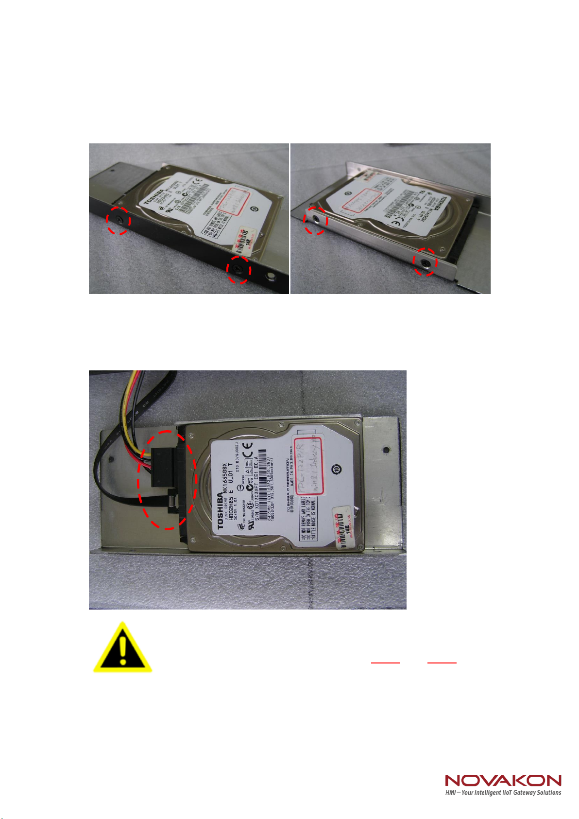
Step 3.
(1) Pick up the "HDD Bracket", and Loosen/tighten the 4 screws on it.
(2) Install a new HDD, and plug in SATA cable and SATA power cable.
Notice that the bracket supports only 7mm and 9mm
HDD/SSD.
Step 4.
(1) Replace the HDD cover
Table of contents
Other NOVAKON Touch Panel manuals


