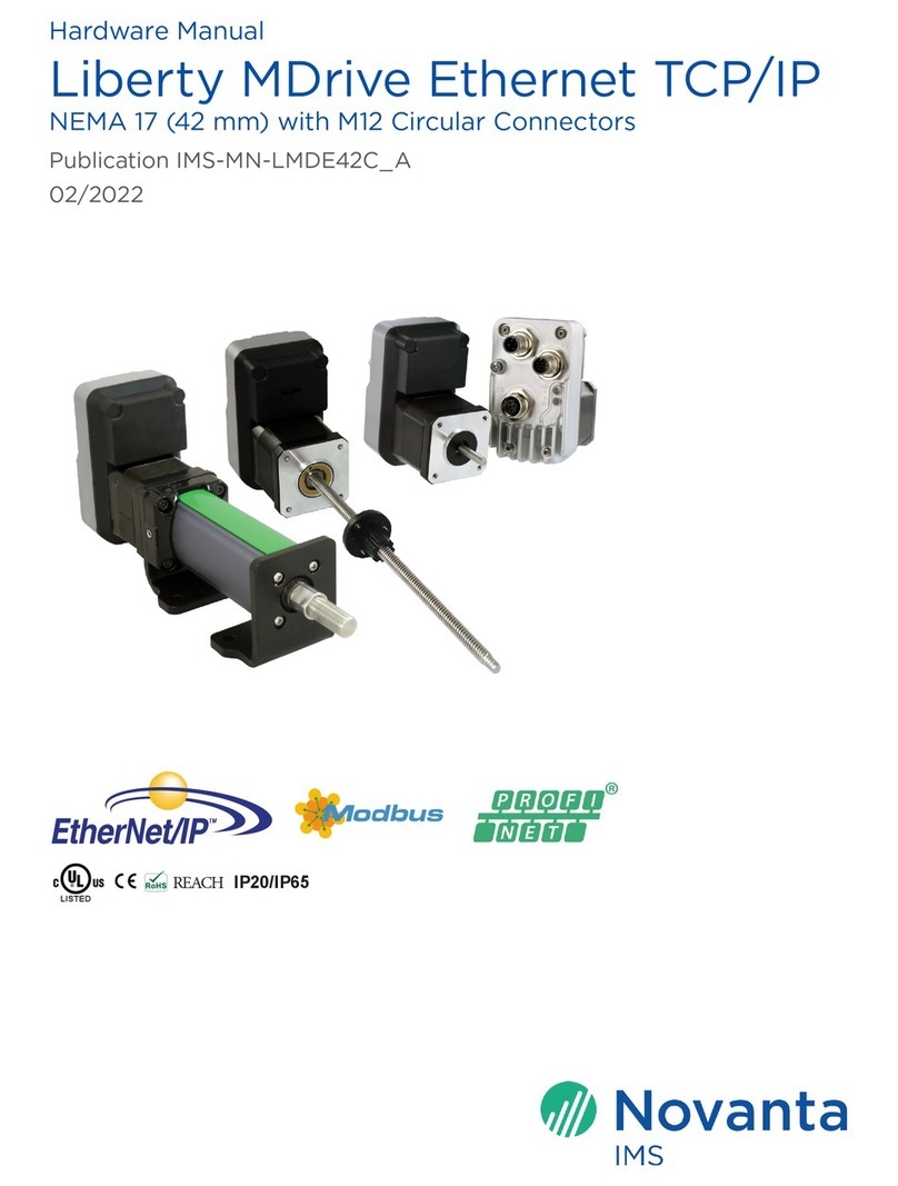
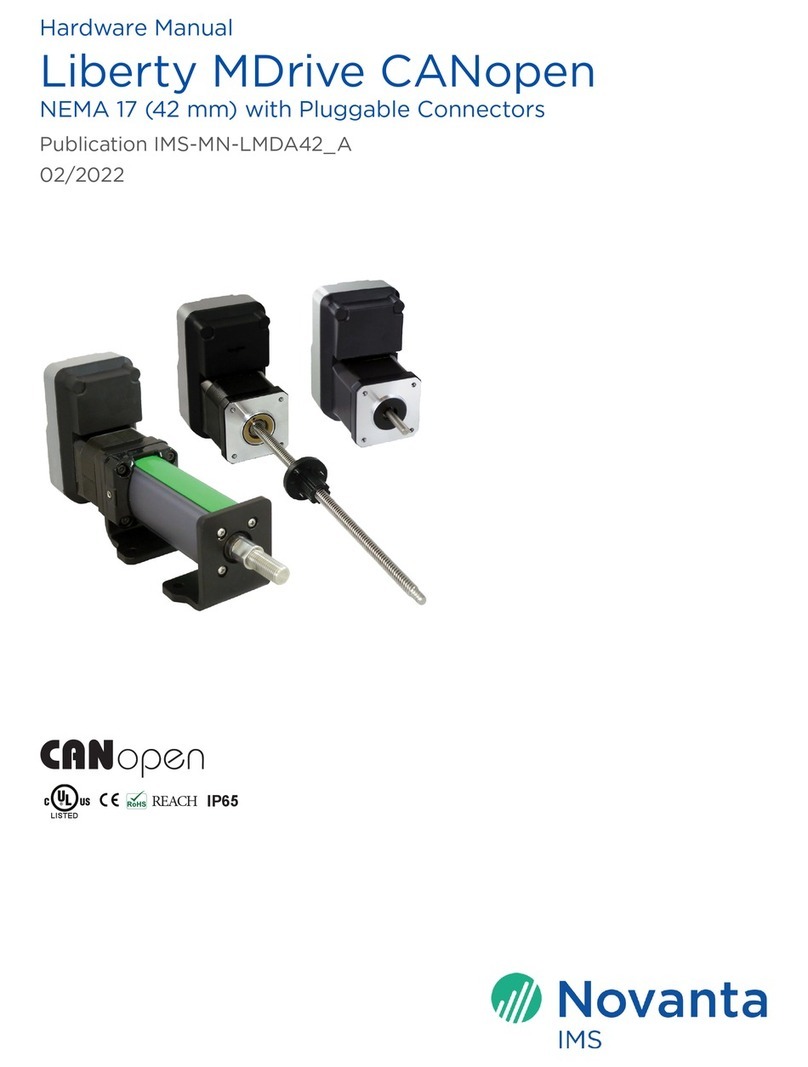
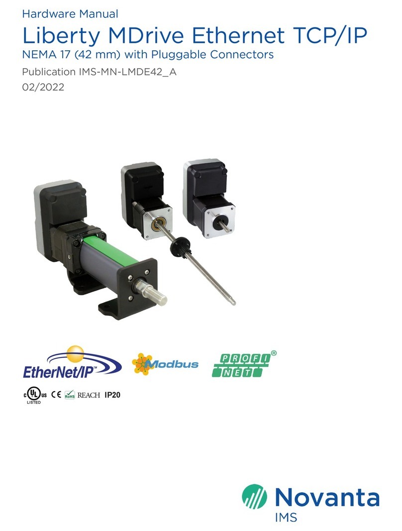
Novanta LMD23 User manual

Hardware Manual
Liberty MDrive CANopen
NEMA 23 (57 mm) & NEMA 34 (85 mm) with Pluggable Connectors
Publication IMS-MN-LMDA5785_A
02/2022
REACH IP20
LISTED

2IMS-MN-LMDA5785_A
Liberty MDrive CANopen
For information on the availability of products, go to https://novantaims.com/
The information contained in the present document is subject to change without notice. The
technical characteristics of the devices described in the present document also appear online.
The characteristics that are presented in the present document should be the same as those
characteristics that appear online. In line with our policy of constant improvement, we may
revise content over time to improve clarity and accuracy. If there is a difference between the
document and online information, use the online information as reference. All details provided
are technical data which do not constitute warranted qualities.
Some of the product designations are registered trademarks of their respective owners, even if
this is not explicitly indicated.
The information provided in this documentation contains general descriptions and/or technical
characteristics of the performance of the products contained herein. This documentation is
not intended as a substitute for and is not to be used for determining suitability or reliability
of these products for specific user applications. It is the duty of any such user or integrator to
perform the appropriate and complete risk analysis, evaluation and testing of the products with
respect to the relevant specific application or use thereof.
Neither Novanta IMS nor any of its affiliates or subsidiaries shall be responsible or liable for
misuse of the information contained herein. If you have any suggestions for improvements or
amendments or have found errors in this publication, please notify us.
You agree not to reproduce, other than for your own personal, noncommercial use, all or part of
this document on any medium whatsoever without permission of Novanta IMS, given in writing.
You also agree not to establish any hypertext links to this document or its content.
Novanta IMS does not grant any right or license for the personal and noncommercial use of the
document or its content, except for a non-exclusive license to consult it on an “as is” basis, at
your own risk. All other rights are reserved.
All pertinent state, regional, and local safety regulations must be observed when installing
and using this product. For reasons of safety and to help ensure compliance with documented
system data, only the manufacturer should perform repairs to components.
When devices are used for applications with technical safety requirements, the relevant
instructions must be followed. Failure to use Novanta IMS software or approved software with
our hardware products may result in injury, harm, or improper operating results.
Failure to observe this information can result in injury or equipment damage.

3
IMS-MN-LMDA5785_A
Table of Contents
Safety Information 5
Important Information...............................................................................................................5
Qualification of Personnel........................................................................................................5
Intended Use.................................................................................................................................5
Product Related...........................................................................................................................6
About this Manual 8
Terminology Derived from Standards .................................................................................8
Source Documents and Software .........................................................................................9
Writing Conventions and Symbols.......................................................................................9
Documentation and Literature References .......................................................................9
Website Directory ......................................................................................................................10
Documentation Feedback ......................................................................................................10
Chapter 1: Introduction 11
About this Product ....................................................................................................................12
Unit Overview ..............................................................................................................................12
Components and Interfaces...................................................................................................13
Conditions for UL 508C...........................................................................................................15
Name Plate....................................................................................................................................16
Part Number Identification.....................................................................................................17
Chapter 2: TechnicalData 20
Certifications................................................................................................................................ 21
Environmental Conditions ......................................................................................................21
Mounting Data.............................................................................................................................22
Mechanical Data ........................................................................................................................ 25
Electrical Data ............................................................................................................................ 30
Rotary Motor Data .................................................................................................................... 33
External Linear Actuator Data ............................................................................................. 35
Electric Cylinder Data.............................................................................................................. 36
Electric Cylinder Performance ............................................................................................ 36
Chapter 3: Engineering 37
External Power Supply Units ................................................................................................ 38
Auxiliary Power Supply............................................................................................................41
Wiring and Shielding.................................................................................................................41
Ground (Earth) Design............................................................................................................ 42
Monitoring Functions............................................................................................................... 43

4IMS-MN-LMDA5785_A
Liberty MDrive CANopen
Chapter 4: Installation 44
Electromagnetic Compatibility, EMC................................................................................. 46
Mechanical Installation............................................................................................................ 47
Supply Voltage VDC Connection........................................................................................ 49
Multifunction Interface Connection.....................................................................................51
Signal Input Circuits ..................................................................................................................52
Power Output Circuits............................................................................................................. 55
Signal Output Circuit ............................................................................................................... 56
Analog Input ................................................................................................................................57
Communications Interface Connection ............................................................................ 58
Checking Wiring ........................................................................................................................ 59
Chapter 5: Configuration 60
Preparing for Configuration .................................................................................................. 62
Configuration via Layer Setting Services......................................................................... 62
Chapter 6: Operation 63
Basics............................................................................................................................................. 64
CANopen DSP402 Operation Modes ................................................................................ 66
Operation by hMT Modes....................................................................................................... 68
I/O Operation.............................................................................................................................. 69
Appendix A: Diagnostics and Troubleshooting 71
Operation State and Error Indication ................................................................................. 71
Appendix B: Accessories and Spare Parts 73
Accessories...................................................................................................................................73
Appendix C: Service, Maintenance, and Disposal 74
Service Address ..........................................................................................................................75
Maintenance .................................................................................................................................75
Replacing Units ...........................................................................................................................75
Shipping, Storage, and Disposal.......................................................................................... 76
Appendix D: LMD with Absolute Encoder 77
Overview........................................................................................................................................77
Unboxing Procedure .................................................................................................................77
Connection of the Multifunction Interface .......................................................................77
ICP0531 Encoder Back-up Battery Pack .......................................................................... 78
Glossary 82

5
IMS-MN-LMDA5785_A
SAFETY INFORMATION
Important Information
Notice
Read these instructions carefully, and look at the equipment to become familiar with the device before
trying to install, operate, service, or maintain it. The following special messages may appear throughout
this documentation or on the equipment to warn of potential hazards or to call attention to information that
clarifies or simplifies a procedure.
The addition of this symbol to a “Danger” or “Warning” safety label or message
indicates that an electrical hazard exists which will result in personal injury if the
instructions are not followed.
This is the safety alert symbol. It is used to alert of potential personal injury hazards.
Obey all safety messages and labels that follow this symbol to avoid possible injury or
death.
DANGER
DANGER indicates a hazardous situation which, if not avoided, will result in death or serious injury.
WARNING
WARNING indicates a hazardous situation which, if not avoided, could result in death or serious injury.
CAUTION
CAUTION indicates a hazardous situation which, if not avoided, could result in minor or moderate injury.
NOTICE
NOTICE is used to address practices not related to physical injury.
Qualification of Personnel
Electrical equipment should be installed, operated, serviced, and maintained only by qualified
personnel. No responsibility is assumed by Novanta IMS for any consequences arising out of the
use of this material.
A qualified person is one who has skills and knowledge related to the construction and
operation of electro-mechanical equipment and its installation, and has received safety training
to recognize and avoid the hazards involved.
Intended Use
The product may only be used in compliance with all applicable safety regulations and
directives, the specified requirements, and the technical data.
Prior to using the product, perform a risk assessment in view of the planned application. Based
on the results, the appropriate safety measures must be implemented.
Since the product is used as a component in an entire system, ensure the safety of persons by
means of the design of this entire system (e.g., machine design).
Operate the product only with the specified cables and accessories. Use only genuine
accessories and spare parts.

6IMS-MN-LMDA5785_A
Product Related
Liberty MDrive CANopen
DANGER
POTENTIAL FOR EXPLOSION
Install and use this equipment in non-hazardous locations only.
Failure to follow these instructions will result in death or serious injury.
Any use other than the use explicitly permitted is prohibited and can result in hazards.
Electrical equipment should be installed, operated, serviced, and maintained only by qualified
personnel.
Product Related
DANGER
HAZARD OF ELECTRICAL SHOCK, EXPLOSION, OR ARC FLASH
Remove all power from all devices before connecting or disconnecting inputs or outputs to any
terminal or installing or removing any hardware.
Failure to follow these instructions will result in death or serious injury.
When the system is started, the drives are usually out of the operator’s view and cannot be
visually monitored.
DANGER
EQUIPMENT OPERATION
Only start the system if there are no persons in the zone of operation.
Failure to follow these instructions will result in death or serious injury.
Drives may perform unintended movements because of incorrect wiring, incorrect parameter
settings, incorrect data, user programming bugs, or other errors. Further, interference (e.g.,
electromagnetic interference (EMI)) may cause unpredictable responses in the system.
WARNING
UNINTENDED MOVEMENT
• Carefully install the wiring in accordance with the electromagnetic compatibility (EMC)
requirements.
• Do not operate the drive system with unknown parameter settings or data.
Failure to follow these instructions can result in death, serious injury, or equipment damage.
The designer of any control scheme must consider the potential failure modes of control paths
and, for certain critical functions, provide a means to achieve a safe state during and after a
path failure. Examples of critical control functions are emergency stop, overtravel stop, power
outage, and restart.
WARNING
LOSS OF CONTROL
• The designer of any control scheme must consider the potential failure modes of control paths and,
for certain critical control functions, provide a means to achieve a safe state during, and after a path
failure. Examples of critical control functions are emergency stop and overtravel stop.
• Separate or redundant control paths must be provided for critical control functions.
• System control paths may include communication links. Consideration must be given to the
implications of anticipated transmission delays or failures of the link.
• Each implementation of the product must be individually and thoroughly tested for proper
operation before being placed into service.
Failure to follow these instructions can result in death, serious injury, or equipment damage.

7
Product Related
IMS-MN-LMDA5785_A
Liberty MDrive CANopen
NOTE: For USA: Additional information, refer to NEMA ICS 1.1 (latest edition), “Safety Guidelines
for the Application, Installation, and Maintenance of Solid State Control” and to NEMA ICS 7.1,
(latest edition), “Safety Standards for Construction and Guide for Selection, Installation, and
Operation of Adjustable-Speed Drive Systems”
Drives may perform unintended movements due to mechanical damage to connectors.
Mechanical damage to the connectors may cause erratic or uncontrolled operation. Installation
with a bent or broken mounting flange, motor shaft, or misaligned coupling may cause
unintended behavior and possible destruction of system components as a result.
WARNING
LOSS OF CONTROL, ERRATIC OPERATION AND DESTRUCTION OF MECHANICS
• Do not drop product.
• Leave product in protective packaging until ready for use.
• Carefully inspect connectors prior to installation in a system for mechanical damage.
• Carefully inspect motor shaft and ensure shaft rotates freely without binding.
Failure to follow these instructions can result in death, serious injury, or equipment damage.
Opening LMD heat sinks can affect factory-set encoder alignment and impact Hybrid Motion
Technology (hMT) performance. Tamper seals are used to ensure factory hardware settings
remain unaltered and match the encoder alignment set during the manufacturing process.
WARNING
UNINTENDED EQUIPMENT OPERATION
• Do not open the LMD device housing for any reason.
• Contact a Novanta IMS applications representative if the product exhibits unexplained, erratic, or
incorrect operation.
Failure to follow these instructions can result in death, serious injury, or equipment damage.
Radial (side) loading or axial (thrust) impacts on the shaft may result in premature bearing
failure.
NOTICE
EXCESSIVE RADIAL OR AXIAL LOADS
• Do not exceed the maximum radial or side load limits on the motor shaft.
• Do not apply force that will pull the shaft from the motor as that may compress the pre-load washer,
causing the rotor to move.
• Do not allow the shaft to be subject to impact forces or otherwise struck by external objects.
Failure to follow these instructions can result in equipment damage.
NOTE: For additional information, contact a Novanta IMS Applications representative.

8IMS-MN-LMDA5785_A
ABOUT THIS MANUAL
Terminology Derived from Standards
The technical terms, terminology, symbols and the corresponding descriptions in this manual,
or that appear in or on the products themselves, are generally derived from the terms or
definitions of international standards.
In the area of functional safety systems, drives and general automation, this may include, but
is not limited to, terms such as safety, safety function, safe state, fault, fault reset, malfunction,
failure, error, error message, dangerous, etc.
Among others, these standards include:
IEC/EN 61131-2:2007 Programmable controllers, Part 2: Equipment requirements and tests.
ISO 13849-1:2015 Safety of machinery: Safety-related parts of control systems. General principles for
design.
EN 61496-1:2013 Safety of machinery: Electro-sensitive protective equipment. Part 1: General requirements
and tests.
ISO 12100:2010 Safety of machinery: General principles for design - Risk assessment and risk reduction.
IEC/EN 60204-1:2006 Safety of machinery: Electrical equipment of machines - Part 1: General requirements.
ISO 14119:2013 Safety of machinery: Interlocking devices associated with guards - Principles for design
and selection.
ISO 13850:2015 Safety of machinery: Emergency stop - Principles for design.
IEC/EN 62061:2015 Safety of machinery: Functional safety of safety-related electrical, electronic, and
electronic programmable control systems.
IEC 61508-1:2010 Functional safety of electrical/electronic/programmable electronic safety-related systems:
General requirements.
IEC 61508-2:2010 Functional safety of electrical/electronic/programmable electronic safety-related systems:
Requirements for electrical/electronic/programmable electronic safety-related systems.
IEC 61508-3:2010 Functional safety of electrical/electronic/programmable electronic safety-related systems:
Software requirements.
IEC 61784-3:2016 Digital data communication for measurement and control: Functional safety field buses.
2006/42/EC Machinery Directive
2014/30/EU Electromagnetic Compatibility Directive
2014/35/EU Low Voltage Directive
In addition, terms used in the present document may tangentially be used as they are derived
from other standards such as:
IEC 60034 series Rotating electrical machines
IEC 61800 series Adjustable speed electrical power drive systems
IEC 61158 series Digital data communications for measurement and control – Fieldbus for use in industrial
control systems
Finally, the term, “zone of operation” may be used in conjunction with the description of specific
hazards, and is defined as it is for a hazard zone or danger zone in the Machinery Directive
(2006/42/EC) and ISO 12100:2010.
NOTE: The aforementioned standards may or may not apply to the specific products cited
in the present documentation. For more information concerning the individual standards
applicable to the products described herein, see the characteristics tables for those product
references.

9
Source Documents and Software
IMS-MN-LMDA5785_A
Liberty MDrive CANopen
Source Documents and Software
The latest versions of the manuals are available online from:
https://novantaims.com/dloads/product-literature/manuals-3/
Writing Conventions and Symbols
Work Steps
Work steps must be performed consecutively. Work steps will be numbered in order of
expected operation.
A response to a work step may be indicated. This allows verification that the work step has
been performed correctly.
Unless otherwise stated, the individual steps must be performed in the specified sequence.
Bulleted Lists
The items in bulleted lists are sorted alphanumerically or by priority. Bulleted lists are
structured as follows:
• Item 1 of bulleted list
• Item 2 of bulleted list
–Subitem for 2
–Subitem for 2
• Item 3 of bulleted list
Parameters
Parameters are shown as follows
RC Motor Run Current
Units of Measure
Measurements are given in both imperial and metric values. Metric values are given in
parenthesis unless otherwise indicated.
Examples:
1.00 in (25.4 mm)
100 oz-in (70.6 N-cm)
Documentation and Literature References
This document should be used in conjunction with the following documents:
• LMD CANopen
The latest versions of these manuals can be downloaded from:
https://novantaims.com/dloads/

10 IMS-MN-LMDA5785_A
Website Directory
Liberty MDrive CANopen
Website Directory
NOTE: Direct links are subject to change as website and search engine updates occur. Each of
the websites below can also be accessed through menu options on the Novanta IMS Main Page:
https://novantaims.com/
Downloads:
https://novantaims.com/dloads/
Resources:
https://novantaims.com/resources/
Warranty:
https://novantaims.com/warranty-and-disclaimer/
Certifications and Listing Information:
https://novantaims.com/dloads/certificationssustainability/
Contact and Support:
https://novantaims.com/contacts/
CyberSecurity Information:
https://novantaims.com/all-products/cybersecurity/
Knowledge Based Solutions:
https://novantaims.com/resources/troubleshooting/
Documentation Feedback
To provide feedback on this or any Novanta IMS documentation, submit all feedback,
corrections, or concerns to the following e-mail address.
documentati[email protected]om
Please include the following information:
• Document number and revision/print date
• Detailed description of the issue or concern
• Contact information

12 IMS-MN-LMDA5785_A
About this Product
Liberty MDrive CANopen
About this Product
This manual is valid for all NEMA 23 (57 mm) and NEMA 34 (85 mm) LIberty MDrive (LMD)
CANopen products with pluggable connectors. This chapter lists the type codes for these
products. The type code can be used to identify whether the product is a standard product or
a customized model. This document is applicable to the following products:
Rotary
• NEMA 23: LMDxA57x
• NEMA 34: LMDxA85
External Linear
• NEMA 23: LMDxA571xLxxxxxxxx
Unit Overview
The “LMD CANopen” consists of a stepper motor and integrated electronics. The product
integrates interfaces, drive and control electronics, and the power stage. There are three basic
control variants:
• Closed Loop with hMT: loop is closed by a 1000-line (4000 edge) magnetic encoder. May be
operated as:
–hMT off: standard encoder functions for position and stall monitoring.
–hMT on: enhanced closed loop functions such as anti-stall and position make-up.
• Absolute with hMT: Closed loop with multi-turn absolute encoder, which will retain position
information for a limited time upon loss/removal of power. The standard encoder and hMT
features will function as on a closed loop model. See Appendix D for details.
• Open Loop: open loop stepper control.
Operating Modes
The “LMD CANopen” uses DS301 communication profile as the interface between device
profiles and CAN bus. It was specified in 1995 under the name DS301 and defines uniform
standards for common data exchange between different device types under CANopen.
The DSP402 device profile describes standardized objects for positioning, monitoring and
settings of drives.
• Profile position: defines the positioning of the drive. Speed, position, and acceleration can be
limited. Profiled moves using a trajectory generator are also possible.
• Homing mode: describes the various methods to find a home position, reference point, date,
or zero point on start up, or via an immediate mode command.
• Profile Velocity: used to control velocity of the drive with no special regard of the position.
It supplies limit functions and trajectory generation.
• Profile Torque: defines the torque control with all related parameters. (Available on closed
loop models only.)
• Cyclic Synchronous Position: used to define position control where the device, or multiple
devices, initiate and complete a point to point move at a specified time.

13
Components and Interfaces
IMS-MN-LMDA5785_A
Liberty MDrive CANopen
Components and Interfaces
The NEMA 23 (57 mm) product is shown below. The NEMA 34 (85 mm) has identical
components and interfaces.
A
B
C
D
E
F
G
(A) Electronics housing
(B) Two-phase stepper motor
(C) DC power interface
(D) Multifunction interface
(E) CANopen interface
(F) Protective earth (PE)
(G) Light-emitting diode (LED) indicators
Components
Motor
The motor is a two-phase brushless stepper motor. The step angle of the motor is 1.8°.
Electronics Housing
The electronics system is comprised of control electronics and the power stage.
The drive system is controlled by a CANopen master sending Service Data Object (SDO) and
Process Data Object (PDO) data over CAN bus 2.0b active.
Interfaces
DC Power Supply Voltage
The supply voltage VDC supplies the drive and control electronics and the power stage.
The ground connections of all interfaces are galvanically connected. For more information on
ground connections and protection against reverse polarity, see “Ground (Earth) Design” on
page 42.

14 IMS-MN-LMDA5785_A
Liberty MDrive CANopen
Multifunction Interface
The multifunction interface operates at the following signal levels:
• +12V to +-------------------------------------------log signal is not isolated.
The +5V to +24V input signals are programmable as general purpose or to predefined
functions.
The output is a 5.5 mA signal output which can be defined as high speed trip.
The reference voltage or current is applied to the analog input and may be used for a number
of programmatically defined operations.
CANopen Interface
The CANopen interface provides a connection to the CAN bus.
A computer may be connected to the interface via a Universal Serial Bus (USB) to CANopen
converter or the unit may be connected to a CANopen master device such as a Programmable
Logic Controller (PLC).
Commissioning is accomplished by using Layer Setting Services or by using the CANopen
Configuration Utility, which is part of the LMD Software Suite (LSS), available for download at
https://novantaims.com/.
The CANopen interface is also used for firmware upgrades. Upgrades require the CANopen
Configuration Utility and the MD-CC501-000 or equivalent PEAK/Phytec CANopen converter.
CANopen model LMD products are identifiable by the white insert in the CANopen interface
DB9 connector.
Protective Earth
PE provides a means of grounding to the device chassis.

15
Conditions for UL 508C
IMS-MN-LMDA5785_A
Liberty MDrive CANopen
Conditions for UL 508C
The following conditions must be met if the product is used to comply with UL 508C.
Ambient temperature during operation:
• Surrounding air temperature [°C] 0 ... +50.
Pollution degree:
• Use in an environment with pollution degree 2.
Power supply:
• Use only power supply units that are approved for over-voltage category III.
• Wiring - Use only 60/75°C copper conductors.
Safety Integrity Level (SIL) Probability of Failure/Hour (PFH)
at high or continuous demand
4≥10-9 ... <10-8
3≥10-8 ... <10-7
2≥10-7 ... <10-6
1≥10-6 ... <10-5
Hardware Fault Tolerance (HFT) and Safe Fail Fraction (SFF):
Depending on the SIL for the safety system, the IEC 61508 standard requires a specific
hardware fault tolerance HFT in connection with a specific proportion of safe failures SFF (safe
failure fraction). The hardware fault tolerance is the ability of a system to execute the required
safety function in spite of the presence of one or more hardware faults. The SFF of a system is
defined as the ratio of the rate of safe failures to the total failure rate of the system. According
to IEC 61508, the maximum achievable SIL of a system is partly determined by the hardware
fault tolerance HFT and the safe failure fraction SFF of the system.
SFF HFT Type A Subsystem HFT Type B Subsystem
0 1 2 0 1 2
< 60% SIL1 SIL2 SIL3 — SIL1 SIL2
60% ...<90% SIL2 SIL3 SIL4 SIL1 SIL2 SIL3
90% ...<99% SIL3 SIL4 SIL4 SIL2 SIL3 SIL4
≥99% SIL3 SIL4 SIL4 SIL3 SIL4 SIL4
Fault Avoidance Measures
Systematic errors in the specifications, in the hardware and the software, usage faults and
maintenance faults of the safety system must be avoided to the maximum degree possible.
To meet these requirements, IEC 61508 specifies a number of measures for fault avoidance
that must be implemented depending on the required SIL. These measures for fault avoidance
must cover the entire life cycle of the safety system, i.e. from design to decommissioning of the
system.

16 IMS-MN-LMDA5785_A
Name Plate
Liberty MDrive CANopen
Name Plate
The name plate contains the following information:
(1) Part number
(2) Nominal voltage
(3) Max. Holding torque
(4) Max required input current
(5) Serial number
(6) Date of manufacture
(7) Communication interface
(8) Data matrix
(9) Ingress protection rating

17
Part Number Identification
IMS-MN-LMDA5785_A
Liberty MDrive CANopen
Part Number Identification
LMD Rotary Motor
The following graphic displays a breakdown of the LMD rotary motor part number
identification.
LMD O A 85 1
Product
LMD = standard torque motor
LMH1 = high torque motor
Control Type
A = CANopen
Feedback
O = Open loop (no encoder)
C = Closed loop (with encoder)
A = Absolute encoder
Size
57 = NEMA 23 (57 mm)
85 = NEMA 34 (85 mm)
Length
1 = 1 stack
2 = 2 stacks
3 = 3 stacks
1 NEMA 23 (57 mm) motors only

18 IMS-MN-LMDA5785_A
Part Number Identification
Liberty MDrive CANopen
LMD External Linear Actuators
The following graphic displays a breakdown of the LMD external linear actuator part number
identification.
Linear actuator
-L = Linear
Connector Style
P = Pluggable, IP20
Shaft style
3 = External
Screw lead / pitch (travel/rev)
A = 0.250" / 6.35mm
B = 0.125" / 3.175mm
C = 0.063" / 1.600mm
Screw end finish
M = Metric threaded
U = UNC threaded
S = Smooth
Z = None
Screw length
available in 0.1” increments
030 = Minimum 3.0" / 76.2mm
180 = Maximum 18.0" / 457.2mm
Nut
G = General purpose
A = Anti-backlash
Coating
T = Teflon®
Z = None
LMD O A 57 1 P -L A 3 M 030 G T
Product
LMD = standard torque motor
Control Type
A = CANopen
Feedback
O = Open loop (no encoder)
C = Closed loop (with encoder)
A = Absolute encoder
Size
571 = NEMA 23 (57 mm)
Length
1 = 1 stack
1 NEMA 34 (85 mm) not available as an External Linear Actuator.

19
Part Number Identification
IMS-MN-LMDA5785_A
Liberty MDrive CANopen
LMD Electric Cylinders (eCylinders)
The following graphic displays a breakdown of the LMD eCylinder part number identification.
Linear actuator
-C = Electric cylinder
Connector Style
P = Pluggable, IP20
Nut
S = PEEK Blend
Lead / Pitch (travel/rev)
A = 0.100” / 2.54mm
B = 0.250” / 6.35mm
C = 0.500” / 12.70mm
D = 1.000” / 25.40mm
Stroke length
available in 0.1” increments
020 = Minimum 2.0" / 50.8mm
180 = Maximum 18.0" / 457.2mm
Mounts
M = Flange mounts
F = Foot mounts
Options
NN = Reserved
LMD O A 57 1 P -C S A 020 M NN
Product
LMD = standard torque motor
Control Type
A = CANopen
Feedback
O = Open loop (no encoder)
C = Closed loop (with encoder)
A = Absolute encoder
Size
571 = NEMA 23 (57 mm)
Length
1 = 1 stack
1 NEMA 34 (85 mm) not available as an Electric Cylinder.

20 IMS-MN-LMDA5785_A
Chapter 2:
TechnicalData
What’s in this Chapter?
This chapter contains information on the ambient conditions and on the mechanical and
electrical properties of the device family and accessories.
This chapter includes the following topics:
Topic Page
Certifications 21
Environmental Conditions 21
Mounting Data 22
Mechanical Data 25
Electrical Data 30
Rotary Motor Data 33
External Linear Actuator Data 35
Electric Cylinder Data 36
This manual suits for next models
5
Table of contents
Other Novanta Engine manuals
Popular Engine manuals by other brands

Nice
Nice NEOSTART A Series Instructions and warnings for the fitter
Regal
Regal Genteq Evergreen IM installation guide
Briggs & Stratton
Briggs & Stratton Vanguard Diesel 432447 Operating & maintenance instructions
Briggs & Stratton
Briggs & Stratton 250000 Series Operator's manual
Briggs & Stratton
Briggs & Stratton 90000 series operating & maintenance manual

Traxxas
Traxxas Velineon 380 instructions

