NovaSail NS 360 Pro User manual

Operating Manual
v1.0

2
Introduction. . . . . . . . . . . . . . . . . . . . . . . . . . . . . . . . . . . . . . . . . . . . . . . . . . . . 3
Installation . . . . . . . . . . . . . . . . . . . . . . . . . . . . . . . . . . . . . . . . . . . . . . . . . . . . 4
Controls and display description . . . . . . . . . . . . . . . . . . . . . . . . . . . . . . . . . . 5
• Modes and sub-modes................................................................. 5
• Controls and display description .................................................. 5
Operations. . . . . . . . . . . . . . . . . . . . . . . . . . . . . . . . . . . . . . . . . . . . . . . . . . . . . 6
• Switching power on and off .......................................................... 6
• Switching backlight on and off...................................................... 8
• Switching modes and sub-modes ................................................ 8
• PS record Status ....................................................................... 9
• Speed mode ................................................................................. 9
• To reset the maximum speed and the trip distance.................... 10
• Velocity made good.................................................................... 10
• Magnetic heading compass mode.............................................. 11
• Sub-modes of the Magnetic Heading compass.......................... 12
• Timer mode ................................................................................ 12
• Start line distance ...................................................................... 14
• Waypoint mode: Wxx ............................................................... 15
• Route mode: Rxx ...................................................................... 17
• Current PS coordinates ........................................................... 18
• Central Bar graph....................................................................... 19
• Lift and Header indicators .......................................................... 19
Advanced Operations . . . . . . . . . . . . . . . . . . . . . . . . . . . . . . . . . . . . . . . . . . 21
• WAY setup mode ....................................................................... 21
• PC mode .................................................................................... 22
User calibration o the magnetic compass . . . . . . . . . . . . . . . . . . . . . . . . . 24
Limited Warranty . . . . . . . . . . . . . . . . . . . . . . . . . . . . . . . . . . . . . . . . . . . . . . 34
Disclaimer . . . . . . . . . . . . . . . . . . . . . . . . . . . . . . . . . . . . . . . . . . . . . . . . . . . . 35
Contents
3
Welcome to the
A complete racing system derived from the legacy, the
includes a PS speedo, gyro-compensated magnetic compass, race timer,
distance to the start line and all other essential and advanced race functions.
The new features a Bluetooth communication transceiver
offering a wide range of functions and applications:
•
Record up to 1248 hours of racing (1 point / 30 seconds)
•
Replay on oogle Earth and other navigational software
•
Computer management of 100 waypoints, including their coordinates and
descriptions
•
Computer management of 20 routes imported from oogle Earth and
defined by existing waypoints
•
Updates with new features
The usage of the is greatly simplified with large and dedicated
buttons for starting the timer and defining the start line points, and the port and
starboard references at your finger tips.
Introduction

4
The mounting location should be as far as possible from any magnetic objects to
avoid any interference with the compass sensor.
The should be ideally mounted close to the vertical and
horizontal planes.
Note:
Wherever you mount the , it shouldn’t be flush to any
thick surface such as the hull, so that the sensitivity of the embedded GPS
receiver is not affected.
Note:
If your isn’t facing the same direction as the boat, you
can compensate this difference in the parameter tab of the Novasail Wireless
anager PC software.
Installation

5
Modes and sub-modes
Timer: TIM
Speed: SPE
•
High: High sensitivity
•
Med: Medium sensitivity
Timer
Upper line mode
selection
Backlight ON/OFF
Lower line mode
selection
Power ON/OFF
Sub-mode
selection
Comittee Boat reference (SLD)
Starboard angle reference
Safety leash
attachment
Pin reference (SLD)
Port angle reference
PC mode entry
Upper line
screen
Lower line
screen
Mode
display
Sub-mode
display
PS record status
Light sensor
Battery cap
Header/lift
indicator
Backlight indicator Battery level indicator
Timer ON
indicator
Central bar-
graph indicator
Units
Main display
lower line Waypoint setup
mode entry
Controls and display description

6
•
Low: Low sensitivity
•
MAX: Maximum speed
•
TRiP: Total distance
Magnetic Heading: HDG
•
High: High sensitivity
•
Med: Medium sensitivity
•
Low: Low sensitivity
•
GPS: PS heading (course over ground)
•
ROLL: Roll angle indicator (angle of heel)
Start Line Distance: SLD
Velocity Made ood: VMG
Waypoints: Wxx
•
W00 to W99: Waypoint 0 to 99
Routes: Rxx
•
R01 to R20: Route 1 to 20
Current PS coordinates: Latitude & Lo gitude
Switching power on and o
•
Make sure the battery is installed with the correct polarity and has enough
remaining power (positive pole inserted first).
•
Press the lower to start the device. A beep will be emitted.
•
Press and hold the lower for more than 4 seconds until the screen
displays OFF and the sequence “3”, “2”, “1” is finished. A beep will be
emitted when the device turns off.
The device will turn off automatically when it remains in the horizontal position for
more than 3 minutes. A beep will be emitted 3 seconds before it turns off.
Operations

7
Upon switching on, the remaining memory time for the PS data logger is
displayed for 5 seconds. This ’ PS LO ’ time is given in hours as shown below.
Note:
If the device does not turn on, you need to check that the battery is fully
charged, that the battery compartment is clean, dry and the polarity is correct. No
liquid should get i to the battery compartme t otherwise this may cause
internal damage. The 2 springs for +/- contacts in the battery compartment can be
removed/cleaned with rubbing alcohol or similar and then put back in place.
Note:
If the battery is almost discharged, the GPS functions are automatically
deactivated (’OFF’ is displayed) in order to save power. Only the functions linked
to the magnetic compass are activated and the battery indicator will blink.
Note:
Until enough satellites are locked, the is not ready for
use. For the modes SPE, SLD, V G and Wxx, the screen displays ’---’. For the
AX speed sub-mode, the maximum value is displayed but blinking until ready.
Note:
Disposable alkaline batteries are not recommended, but can be used to
reach the maximum 40-hour battery life of the . It is ma datory
to remove disposable batteries if the device is not going to be used for a
prolonged period of time (a week or more) to avoid battery leakage, as this will
irreversibly damage the battery compartme t. Therefore we recommend that
rechargeable batteries with a low self discharge rate should be used (normal
Operations

8
rechargeable batteries lose their stored energy quickly even when they are not
being used), and will last for 30 hours or more. Recommended batteries are
SANYO ENELOOP, GP RECYKO+, UNIROSS HYBRIO (2000mA or more typical
capacity).
Switching backlight on and o
•
After the power of the is turned on, the backlight is
automatically switched ON/OFF by the internal light sensor detector.
•
The backlight can be manually switched ON or OFF: press and hold the
upper for more than 1 second until the icon is displayed on the
screen.
•
To turn off the backlight, press and hold the upper for more than 1
second until the icon disappears from the screen.
Note
:
Once the backlight has been switched ON or OFF manually, the
automatic light sensor detector will no longer be used and will resume upon the
next power cycle.
Note
:
In PC mode (see Advanced Operations, page 22), the backlight can be
only switched ON or OFF manually.
Switching modes and sub-modes
•
Choose the mode and sub-mode required by pushing the ‘mode’ button and
then the and for the sub-mode selection.
•
You are free to choose any mode on each line independently.
Operations

9
GPS record status
•
When the icon is displayed, the PS trace is recording.
•
The Novasail Wireless Manager PC software gives you three options at
startup: PS trace record disabled, PS trace record always ON and PS
trace record starts at the end of timer countdown.
•
For more information please refer to the online manual of the Novasail
Wireless Manager PC software for the .
Speed mode: SPE
This mode provides the speed over ground of the boat as measured by the PS
receiver. The sub-modes provide several speed resolutions, the trip distance and
the maximum speed. The boat speed is displayed in knots (kts) with a resolution
of 0.1 knots. The minimum speed is 0.5 knots.
•
Use the and to scroll the sub-modes.
Speed sub-modes
•
High: High sensitivity
The high sensitivity speed allows a very sensitive reading of any speed variation.
•
Med: Medium sensitivity
This sub-mode provides an average speed of the boat over a short period of time.
This is particularly useful when sailing with big waves upwind or downwind.
•
Low: Low sensitivity
This sub-mode provides an average speed of the boat over a longer period of
time. This is particularly useful in rough conditions with lots of speed changes.
Operations

10
•
Max: Speed MAXimum
The maximum speed that the boat has reached since the last reset.
•
trip: trip distance
The trip mode displays the total distance made by the vessel since the last reset.
To reset the maximum speed or trip dista ce:
•
Select the maximum speed or the trip distance in the sub-mode
•
Tilt the device 90 degrees to the right or left for more than 3 seconds
•
The value is reset
Note
:
For the ‘ ax’ and ’trip’ sub-mode don’t forget to reset the value before
your next sail begins to ensure the value displayed refers to the new sail.
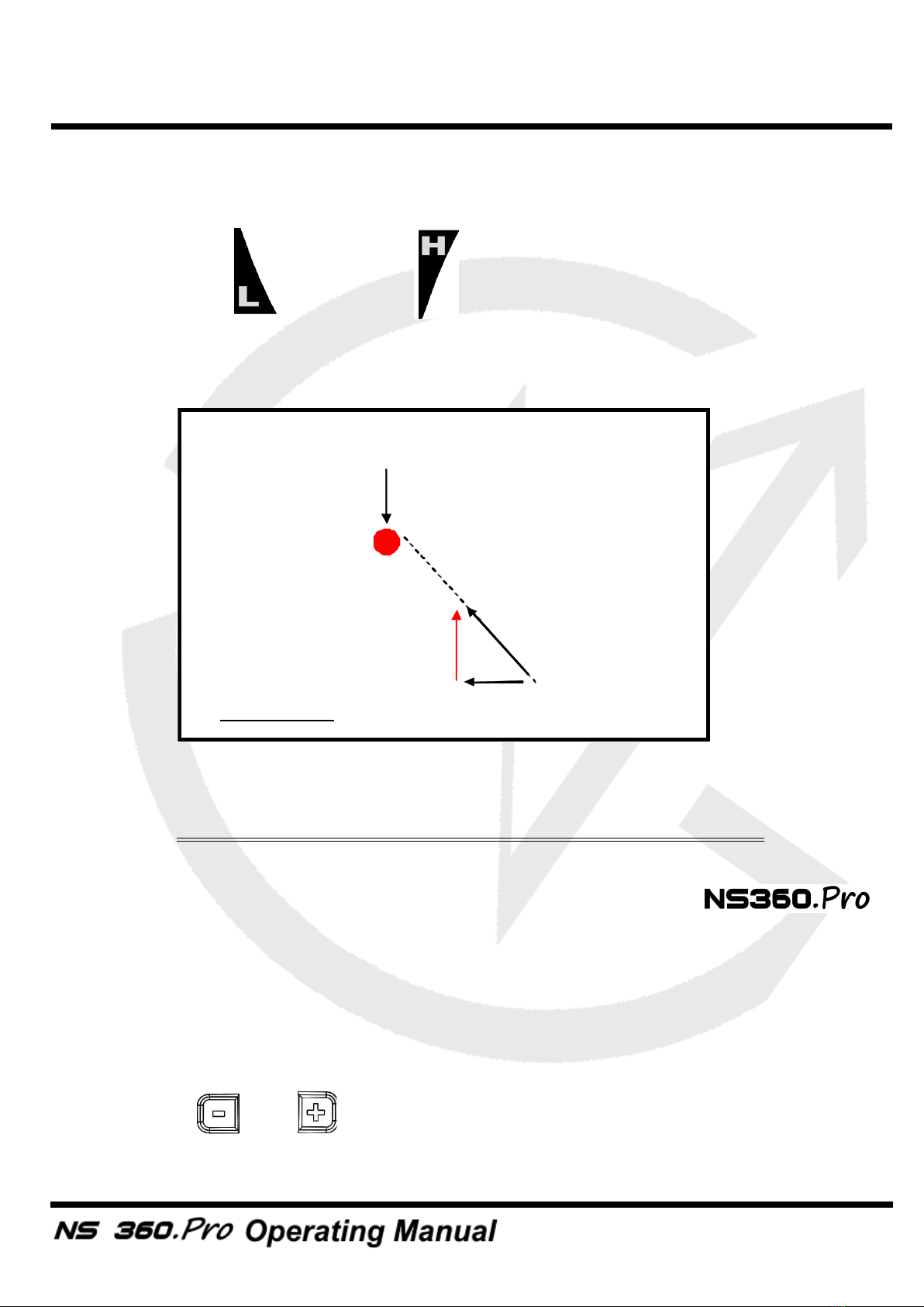
Velocity made good mode: VMG
This mode provides the projected speed of the boat on the reference (wind)
direction, which is deducted from the port and starboard angle references
captured. The VM is shown in knots (kts) and the memorized wind direction in
use will be indicated on the main display.
To set a d adjust the wi d directio i VMG mode
•
Press and hold to capture the port angle direction
•
Press and hold to capture the starboard angle direction
•
You may enter or adjust the wind direction value with the and
Note
:
The V G speed sensitivity is adjusted (High/ ed/Low) by using the
same sensitivity of the speed in SPE mode on the same line (lines are
Operations
11
independent, therefore the sensitivity can be different on the upper and lower
line).
Note
:
The lift and header icons will be shown according to the
memorized port and starboard reference directions. They will be displayed only
after these 2 angles are memorized.
Mag etic Headi g compass mode: HDG
To win races you need to react to the smallest wind shifts. The
digital compass delivers precise and reliable heading information to help you to
tack and jibe at the most suitable times.
The sensitivity of the compass can easily be adjusted to High, Medium or Low by
scrolling through the sub-modes.
•
Use the and to scroll the sub-modes
VMG
V
wasted
V
actual
Wind Direction
VMG DIAGRAM
Operations
12
Sub-modes of the Mag etic Headi g compass:
•
High: high sensitivity
When sailing with light winds and flat seas, high sensitivity allows you to
appreciate very small wind variation.
•
Med: medium sensitivity
Medium sensitivity is more suitable for race boats under medium wind and sea
conditions. Dinghy racers will appreciate this mode.
•
Low: Low sensitivity
Under low sensitivity more subtle variations due to big waves and sudden gusts
are filtered.
Note:
The magnetic variation of your geographical location can be
compensated in the parameter tab of the Novasail Wireless anager PC
software.
•
GPS: GPS based compass
This sub-mode provides the route direction followed by the boat measured by the
PS receiver (course over ground)
•
ROLL: Roll angle indicator mode (angle of heel)
Used in Roll angle indicator (ROLL) mode, the displays the roll
angle of the boat. The angle range can vary from 0 to +/-180 degrees.
Note:
The roll angle displayed is based on the mounting roll
angle.
TIMER mode: TIM
This mode offers a 5-minute countdown timer, which can be synchronized to 5/4/
3/2 and 1 minute.
Operations
13
When counting down, a short beep sounds:
•
each minute until the last minute
•
each ten seconds until the last 10 seconds
•
each second until the start time
At the start time:
•
a long beep sounds
•
the timer starts counting the race duration in minutes and hours
Start a d stop the TIMER:
•
Press to start the timer countdown at the last synchronized minute (5/
4/3/2 or 1 minute)
•
Press and hold to stop the timer and reset to the last synchronized
minute
Sy chro ize the TIMER:
•
In any mode press will display the timer on the upper line and result
in the following action:
- if the timer is stopped, start and set the timer value to the last
synchronized minute
- if the timer is down-counting and the timer value is lower than 3:45, set
the timer value to the lower minute
- if the timer is down-counting and the timer value is greater than 3:45, set
the timer value to 4 minutes
•
With the timer mode displayed and the timer stopped, press the upper
to synchronize to the lower minute or press the upper to synchronize to
the upper minute. The upper/lower minute selected will be used as the new
synchronized minute value (the timer will re-start from this value)
Note:
With the GPS logger synchronized to the upcounting of the timer, the
GPS logger stops when the timer is stopped or restarted in order to log the end of
the current sail.
Operations
14
Note
:
When the down counter reaches 0:00, the timer and the Start Line
Distance will switch automatically to the modes selected in the parameter tab of
the Novasail Wireless Manager PC software.
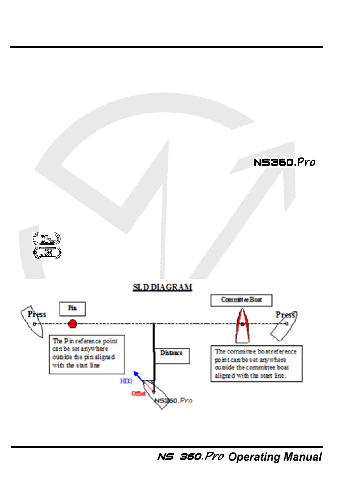
Start Li e Dista ce: SLD
Knowing the exact distance in meters to the start line gives a huge advantage in
helping you start ahead of the fleet and even win the race. The
Start Line Distance function is the most advanced on the market as it combines
the latest multi-constellation satellites receiver and a dynamic boat offset
compensation, calculated with the real boat magnetic heading to the start line.
The maximum distance displayed is 999 meters to the start line.
The start line consists of 2 points that have to be aligned with the start line:
•
: Committee boat
•
: Pin
Operations

15
To memorize the start li e poi ts
•
Press when you reach the committee boat reference point
•
Press when you reach the pin reference point
•
The distance in meters is now displayed on the data line
Note:
If the start line is modified by the committee, you may be required to re-
enter one or both reference points.
Note:
The distance from the front of the boat to the can be
defined in the parameter tab of the Novasail Wireless anager PC software.
Note:
When the down counter reaches 0:00, the timer and the Start Line
Distance will switch automatically to the modes selected in the parameter tab of
the Novasail Wireless anager PC software.
Waypoi t mode: Wxx
The waypoint mode has been made for those who are sailing island races and
require information such as the direction, angle difference, speed and distance to
reach the selected pre-defined waypoint. Up to 100 waypoints can be memorized:
W00 to W99. For each waypoint selected on the , the direction,
the heading difference between the boat and the direction to the waypoint, speed
and distance needed to reach it are displayed sequentially.
Note:
The display timings of the directions, angle, speed and distance are
defined by the parameters Waypoint Heading, Waypoint Speed, Heading
Difference and Waypoint Distance in the Novasail Wireles anager PC software.
Please refer to the installed online documentation for more details.
Operations

16
To use a waypoi t
•
By default, W00 is displayed on the mode line.
•
Use the and to select the required waypoint, from W00 to W99.
•
The direction, speed, distance and heading difference are displayed
sequentially.
To Memorize a waypoi t while saili g
•
First select the ‘WAY’ mode on the lower line (the memorization must be
done on the lower line screen, it cannot be done on the upper line screen).
Press the lower or to select the waypoint (from W00 to W99) that
you want to overwrite.
•
Press simultaneously the lower and to memorize the current boat
position into the selected waypoint.
•
The direction, speed and distance to reach it are displayed sequentially.
Note:
The waypoint speed displayed in knots is calculated using the waypoint
position, the boat position, the boat speed and the heading.
Operations

17
Route mode: Rxx
The Route mode has been made for those who are sailing island races and
require information such as the direction and distance to reach the series of pre-
defined waypoints. Up to 20 routes, made up of up to 500 waypoints, can be
memorized: R01 to R20. Each time a route is selected, the direction, speed and
distance needed to reach its wayoints are displayed sequentially.
When getting within 50 to 500 meters of a waypoint (settable thanks to the
Novasail Wireless Manager PC software), the route will switch to the next
waypoint automatically.
To use a route
•
By default, R01 is displayed.
•
A long push on or will allow the selection of the route from R01 to
R20; then a short push on or will decrease/increase the route
number.
•
The name and the waypoint number are displayed sequentially on the sub-
mode column.
•
A push on or will select the previous or the next waypoint into the
current route.
•
The direction, speed and distance to the target waypoint on the chosen
route will be displayed sequentially on the main screen.
Operations

18
Note:
It is necessary to upload the routes into the
Note:
The display timings of the direction, speed, distance and heading
difference are defined by the parameters Waypoint Heading, Waypoint Speed,
Waypoint Distance and Waypoint diff.heading in the Novasail Wireless anager
PC software. Please refer to the online documentation for more details.
Current GPS coordinates
This mode allows the latitude and longitude of the current position to display (in
degrees and decimal minutes). To activate this mode, you need to press the
upper and simultaneously. The latitude is displayed on the upper line
and the longitude on the lower line.
Press any key to exit this mode.
Operations

19
Central Bar Graph
The central bar graph allows the visualization of the heading variations. After a
tack or a jibe, during the average heading calculation, the bar graph displays:
Once calculated, the average heading is used as the reference to display the
variations in degrees. For example means that the current
heading is 3 degrees starboard compared to the average reference heading, with
a 1 degree value for each segment (the value for each segment can be adjusted
in the Novasail Wireless Manager PC software, please refer to the online
documentation for more details)
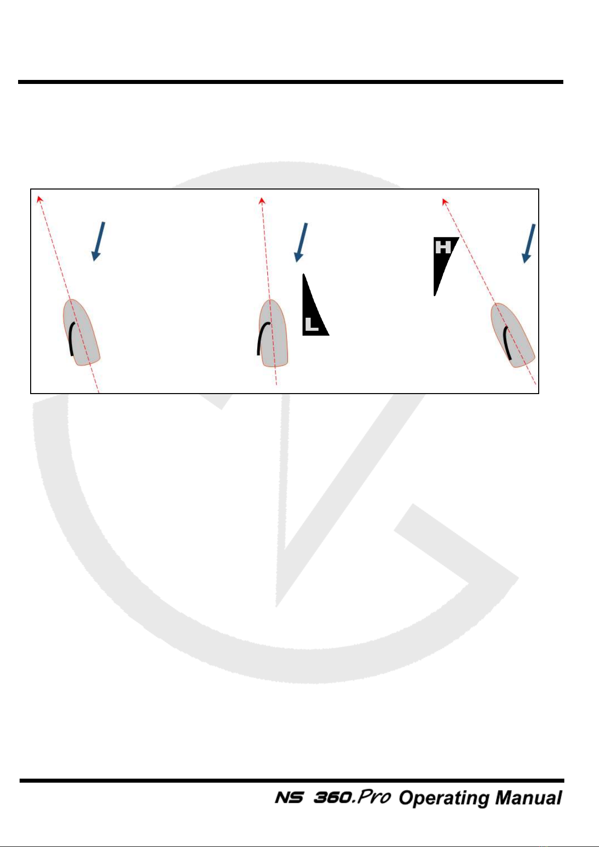
Li t and Header indicators
•
The lift and header icons will be displayed according to the
current heading.The port and starboard reference angles must be
memorized first by pressing and holding the or buttons for
1 second (a beep will be emitted)
Operations
20
Example of lift and headers on port with a 250 degrees angle reference
memorized:
Note:
The lift and header icons won’t be displayed until the port and starboard
reference angles are memorized. These reference angles will be also used for
setting the wind direction in VMG mode.
1 - Port reference angle
captured: 250 degrees
2 - Heading 260 degrees
Lift icon to show
3 - Heading 235 degrees
Header icon to show
Wind
Wind
Wind
Operations
Table of contents
Other NovaSail GPS manuals


Popular GPS manuals by other brands

NAL RESEARCH CORPORATION
NAL RESEARCH CORPORATION 9602-AB quick start guide

Whelen Engineering Company
Whelen Engineering Company OR5001V Installation and service manual

Lark
Lark FreeBird 50.3 user manual

Mio
Mio Cyclo 105 HC quick start guide

FIFOTRACK
FIFOTRACK A500 user manual

Mio
Mio Moov R503T user manual


Bushnell
Bushnell Yardage Pro Yardage Pro owner's manual

Magellan
Magellan eXplorist 500 - Hiking GPS Receiver Reference manual

Hama
Hama MY 1997 operating instructions

Magellan
Magellan 1000M quick guide

Mannesmann
Mannesmann VDO KIENZLE Fleet Manager 100 user manual
Easiphone
Easiphone SOS Tracker with Voice quick start guide