Novatech 1635 User manual

Water Vapour Analyser
Model 1635
August 2009


August 2009
1635 Water Vapour Analyser 1
CONTENTS
1DESCRIPTION & SPECIFICATIONS ...........................................................................................3
2INSTALLING & COMMISSIONING...........................................................................................13
3OPERATOR FUNCTIONS............................................................................................................25
4SETTING UP THE ANALYSER..................................................................................................31
5MAINTENANCE...........................................................................................................................45
APPENDICES
APPENDIX 1 PROBE OR SENSOR EMF TABLES.............................................................................50
APPENDIX 2 CIRCUIT SCHEMATICS................................................................................................52
APPENDIX 3 MODBUS™ REGISTER MAP AND APPLICATION NOTES.....................................61
Note: This manual includes software modifications up to Version 5.18, 12th July 2007
© Copyright NOVATECH CONTROLS PTY. LTD. - 1996 - 2008
This manual is part of the product sold by Novatech Controls Pty. Ltd. ("Novatech Controls") and is provided to the
customer subject to Novatech Controls' conditions of sale, a copy of which is set out herein. Novatech Controls'
liability for the product including the contents of this manual is as set out in the conditions of sale.
All maintenance and service of the product should be carried out by Novatech Controls' authorised dealers.
This manual is intended only to assist the reader in the use of the products. This manual is provided in good faith but
Novatech Controls does not warrant or represent that the contents of this manual are correct or accurate. It is the
responsibility of the owner of the product to ensure users take care in familiarising themselves in the use, operation and
performance of the product.
The product, including this manual and products for use with it, are subject to continuous developments and
improvement by Novatech Controls. All information of a technical nature and particulars of the product and its use
(including the information in this manual) may be changed by Novatech Controls at any time without notice and
without incurring any obligation. A list of details of any amendments or revisions to this manual can be obtained upon
request from Novatech Controls. Novatech Controls welcome comments and suggestions relating to the product
including this manual.
Neither the whole nor any part of the information contained in, or the product described in, this manual may be adapted
or reproduced in any material form except with the prior written approval of Novatech Controls Pty. Ltd.
All correspondence should be addressed to:
Technical Enquires
Novatech Controls Pty Ltd
309 Reserve Road
Cheltenham Victoria 3192 Phone: Melbourne +61 3 9585 2833
Australia Fax: Melbourne +61 3 9585 2844
Website: http://www.novatech.com.au/

August 2009
21635 Water Vapour Analyser
USING THIS MANUAL
The Novatech 1635 Percent Water Vapour Analyser has a variety of user-selectable functions.
Each selection is menu driven, designed for simplicity. For options you are unsure about, read the manual.
Please read the safety information below and the ‘Installation’ section, before connecting power to the analyser.
CAUTION FOR DIRECT FIRED DRYERS OR OVENS
CAUTION 1
The sensing probe is heated to above 700°C and can be a source of ignition. With direct fixed dryers, raw fuel leaks can
occur during burner shutdown, the analyser has an interlocking relay which removes power from the probe heater when
the main fuel shut-off valve power is off. If this configuration does not suit or if it is possible for raw fuel to come into
contact with a hot oxygen probe then the Model 1635 analyser with its heated probe may be unsuitable for your
application. Also read the probe heater interlock caution in section 2.7.
CAUTION 2
The probe heater is supplied with mains voltage, either 240 or 110 VAC. This supply has electrical shock danger to
maintenance personnel. Always isolate the analyser before working with the probe.

August 2009
1635 Water Vapour Analyser 3
1
DESCRIPTION &
SPECIFICATIONS
Section
Number
1.1DESCRIPTION.................................................................................................................................4
1.2SPECIFICATIONS...........................................................................................................................7
1.2.1SPECIFICATIONS – ANALYSER..................................................................................................7
1.2.2SPECIFICATIONS – PROBE ..........................................................................................................7
1.3THE ZIRCONIA SENSOR...............................................................................................................9
1.4THE OXYGEN PROBE..................................................................................................................10
1.5THE REFERENCE GAS SENSOR (RGS-01)................................................................................10
1.6ALARMS........................................................................................................................................10
1.7HEATER SUPPLY .........................................................................................................................10
1.8APPLICATIONS WHERE THE SENSING POINT IS NOT AT ATMOSPHERIC PRESSURE.10
1.9SENSOR IMPEDANCE .................................................................................................................10
1.10AUTO CALIBRATION – ELECTRONICS...................................................................................10
1.11AUTO CALIBRATION CHECKING – PROBES .........................................................................11
1.12PURGE & CALIBRATION CHECK ACCESSORIES..................................................................11
1.13FILTER PURGE PRESSURE SWITCH ........................................................................................11
1.14RS 485 NETWORK (MODBUS™) AND RS 232C PORT ...........................................................12
1.15DRYER OR OVEN TEMPERATURE (AUX) THERMOCOUPLE..............................................12
1.16MODES WITH SWITCHING CAL 2 SOLENOID........................................................................12
1.17WATCHDOG TIMER ....................................................................................................................12
1.18BACK-UP BATTERY....................................................................................................................12

NOVATECH CONTROLS 1635 PERCENT WATER VAPOUR ANALYSER
1.1 DESCRIPTION
The Novatech 1635 Percent Water Vapour Analyser is designed for measuring water vapour in drying and baking
applications, where the drying temperature is above the maximum limit of conventional relative humidity sensors
(typically 130-150°C) or a more robust sensor is preferred. The analyser signal can be used with a conventional
controller to improve the efficiency of industrial drying or baking applications, as well as to optimise the quality of the
product being dried or baked. There are seven basic types of installation for the 1635 analyser (see table below)
22 sensors Indirect 2 Zone n/a n/a
31 sensor Direct, Fixed O2 0.1 - 21.0%
0.1% interval n/a
4
1 sensor Direct Ref'g O2 n/a Ambient Cooled/
Refrig'd Dry
5
2 sensors Direct Fired n/a n/a
6
1 sensor Switched Dry O2 n/a Ambient Cooled/
Refrig'd Dry
7
1 sensor External Dry O2 n/a n/a
82 sensor Direct Fired c/w RH n/a n/a
Setup Step 27
Dry O2 Upd' Mode Setup Step 28
Update Period Setup Step 29
Update Duration Setup Step 30
Update Freeze Setup Step 31
Update Deviation
1n/an/an/an/an/a
2n/an/an/an/an/a
3n/an/an/an/an/a
4
n/an/an/an/an/a
5
Constant/Auto 0.1 - 99.9 hours
1
0.1 hour interval 5-300 minutes
1 minute interval 1-60 minutes
1 minute interval 0.1 - 21.0%
1
0.1% interval
6
Timed/Auto 0.1 - 99.9 hours
0.1 hour interval 5-300 minutes
1 minute interval 1-60 minutes
1 minute interval 0.1 - 21.0%
1
0.1% interval
7n/a n/a n/a n/a n/a
8n/an/an/an/an/a
Directly Fired,
External Dry O2 Input
Directly Fired,
Auto Operation of Cal 2 Solenoid
Directly Fired,
External Drier Temperature, 0-400 Deg C
Indirectly fired,
2 zones
Directly Fired,
Constant Combustion
Directly Fired,
Ambient Cooled/Refrigerated Process gas
on Probe Reference
Directly Fired,
Constant/Auto Operation of Sensor 2
1. Indirectly Heated Dryers and Ovens, 1 Zone
The in-situ probe measures the oxygen content within the drying chamber and calculations are performed to determine
how much of the air space is taken up by water vapour. For indirectly heated dryers or ovens, an oxygen probe and
analyser are all that is required. The oxygen probe uses ambient air as a reference gas.
2. Indirectly Heated Dryers and Ovens, 2 Zones
If the dryer or oven has two zones that you would like to measure the humidity level in, a 1635 analyser can be
configured to read both zones and independently display and transmit the for each zone on independent channels.
3. Directly Heated Dryers and Ovens with Constant Combustion
If the dryer or oven has a fixed combustion system (fixed firing rate), where the reduction of oxygen due to combustion
is constant, then a reference gas sensor may not be necessary to condition reference gas from within the dryer. The
dryer or oven oxygen level can be entered on the analyser keyboard. The percent water vapour can be measured by
gravimetric methods to calculate the correct reading.
August 2009
41635 Water Vapour Analyser

August 2009
1635 Water Vapour Analyser 5
4. Directly Heated Dryers and Ovens with Single Probe and RGS thermocouple
In a system where water vapour % is measured using a single probe, process gas is extracted from the system and
cooled to ambient (RGS thermocouple) temperature or refrigerated to drop out most of the water vapour. The probe
then measures the oxygen difference between the dry cooled process gas and wet process gas to calculate water vapour
%. For ambient cooling the RGS thermocouple must be present for compensation.
5. Directly Heated Dryers and Ovens with Dual Sensors
Where dryers or ovens use direct fired combustion, the oxygen level in the dryer or oven is measured after removing
some or all of the water vapour. The oxygen level of the dried sample is compared to the oxygen level in the wet
measurement in the oven and the amount of water vapour is calculated. The 1231 oxygen probe in the dryer or oven
performs the wet measurement. The dry measurement is performed by the RGS-01, reference gas sensor which draws a
gas sample from the dryer of oven. In this mode, the RGS-01 sensor can be operated in continuous sampling mode, or
auto mode with a solenoid on terminals 45 & 46 controlling flow of sample gas to the probe when the change in
measured wet oxygen exceeds the deviation threshold.
6. Directly Heated Dryers and Ovens with Single Probe with Switched Regference Gas
This mode extends Mode 4 by calculating wet & dry oxygen as well as measuring water vapour using the difference in
wet/dry oxygen. It achieves this by switching the reference gas to the probe between dry process oxygen and reference
air using a solenoid connected to terminals 45 & 46. Switching can be configured to occur automatically when the
change in wet process gas exceeds the deviation threshold, or at set timed intervals. It then uses the wet oxygen reading
and water vapour to calculate the dry process gas oxygen content.
7. Directly Heated Dryers and Ovens with Single Probe and Dry Process Gas on External 4-20mA Input
For systems that have external dry process gas oxygen reading, this measurement can be sent back to the analyser via
the BFT input in the form of a 4-20mA signal as linear scaled 0-25% oxygen dry process gas. In this mode the analyser
calculates water vapour % the same as in Mode 5, using the external input as the dry oxygen measurement instead of an
RGS-01 sensor.
8. Directly Heated Dryers and Ovens with Dual Sensors and the Drier Temperature on External 4-20mA
Input
For systems that require a reading of RH but are using in insitu probe and a sampling oxygen sensor to measure the
water vapour, the drier temperature must be fed into the analyser on the terminals 55&56. This signal must be a 4-
20mA signal ranged for 0-400°C.
What Measuring Units to Use:
The water vapour can be displayed or transmitted in 4 different engineering units.
Water Vapour Percent
Absolute Humidity Kg/Kg
Dew Point Temperature Centigrade / Fahrenheit
Mass Fraction g/Kg
Relative Humidity %
Most industrial processes operate at high temperatures resulting in low RH levels. For this reason it is normally best to
use a reading of % Water Vapour or g/kg of moisture or Dew Point. A dryer or oven temperature thermocouple is only
necessary if Relative Humidity percent is to be displayed or transmitted.

Features
1. The probe can be operated in dryer atmosphere temperatures up to 900°C or higher
2. The output signal is continuous and proportional to the percentage volume of water vapour
3. Various engineering units Selectable from the keyboard -
Water vapour %
Relative Humidity %
g/Kg or lb/lb of moisture
Dew point
4. Fast response, typically 20 seconds
5. Long- term continuous and reliable measurement
8.00
WATER CONTENT (g/Kg)
Repeatability Indirectly Heated
Accuracy Indirectly Heated
PERCENTOFREADING
0.00
0
1.00
100
2.00
3.00
200 300 400
4.00
5.00
6.00
7.00
Repeatability Directly Fired
500 600 700 800 900 1000
Accuracy Directly Fired
Accuracy & Repeatability of 1635 Water Vapour % Analyer Readings
August 2009
61635 Water Vapour Analyser

August 2009
1635 Water Vapour Analyser 7
1.2 SPECIFICATIONS
1.2.1 SPECIFICATIONS – ANALYSER
Model: 1635
Range: Keyboard selectable for the following ranges: -
0–100% volume of water vapour
0-100% Relative humidity (RH)
0-10,000 g/Kg
-50-+100 °C Dew point
all with adjustable span and zero.
Output: Isolated 4–20 mA DC linear
Displays: Various, Refer Section 3.1
Alarms: Various, Refer Section 3.3.1 & 3.3.2
Speed of response: Typically 20 seconds
Accuracy: See graph above
Power Supply: 110/240 VAC, 50/60 Hz 105VA
Environmental Rating Operating Temperature: -25 to 55°C (-15 to 130°F)
Relative Humidity: 5 to 95% (non-condensing)
Vibration: 10 to 150Hz (2g peak)
Degree of Protection IP65 without reference air pump
IP54 with reference air pump
1.2.2 SPECIFICATIONS – PROBE
Model: 1231
Length: 250–1000 mm.
Temperature Range: 0 to 900°C
Process Connection: 1.5" BSP or NPT
Filter: Sintered titanium alloy particulate filter, removable, 30 or 15 micron
Response Time: Typically less than 4 seconds
Operating Temperature: 720°C with integral heater
Heater Voltage: 240 (25% duty cycle) / 110 VAC, 100 watts
Maximum Head Temperature: 150°C with screw terminals / 100°C with weatherproof connector
Reference Gas Connection: 1/8" NPTF.
Probe Cable: Supplied with weatherproof connector to specified length, maximum 100 metres
Probe Life: Typically 2 to 3 years.

1.2.3 SPECIFICATIONS – REFERENCE GAS SENSOR
Model RGS-01
Pump: Integral electric sampling pump
Size 300 H x 125 W x 88 D
Weight 3 Kg
Heater Voltage: 240 (25% duty cycle) / 110 VAC, 100 watts
Maximum ambient air temperature 100°C
Minimum process moisture content 2000 g/Kg
REF
Dryer Chamber
1635
Precentage
Water Vapour
Analyser
Heat Exchanger
1231
Oxygen
Probe
Note: Reference Gas Sensor
not required because
there is no direct
combustion.
Percent Water vapour Measurement in Indirectly Heated Dryer or Oven
REF
Hood
Fan
Combustion Air
Return Duct
Vent 1231
Oxygen Probe
1635
Humidity
Reference
Gas Sensor Analyser
RGS01
Burner
Percent Water vapour Measurement in Directly Heated Dryer or Oven
(Paper Machine Hood Example)
August 2009
81635 Water Vapour Analyser

1.3 THE ZIRCONIA SENSOR
The analyser input is provided from one or two (two where an RGS-01 is required) zirconia oxygen sensors and
thermocouples. The probe is designed to be inserted into the dryer or oven. A reference air supply is required for the
probe. A reference air pump is integral with the 1635 analyser. The RGS-01 withdraws a sample from the dryer of
oven. It uses air as a reference but a pump is not required. The sensor construction is shown below.
Internal electrode wire
Ziconia Disc
Thermocouple
Wires
Electrode Material
(required only
Heater
with heated
probes)
External Wire
Contact
Thermocouple
Junction
Internal Electrode
Four-Bore Thermocouple
Insulating Tubing
Alumina Tube
Schematic View of a Sensor Assembly
The heater control is a time proportioning temperature controller and triac so that the thermocouple junction is
controlled to approximately 720 °C. When exposed to different oxygen partial pressures at the outside and inside of the
sensor, an EMF (E) is developed which obeys the Nernst equation:
() ()
()
⎟
⎟
⎠
⎞
⎜
⎜
⎝
⎛
=OUTSIDE% INSIDE%
ln
4
millivolts
2
2
O
O
F
RT
E
Where T is the temperature (° K) at the sensor (> 650°C), R is the gas constant, F is the Faraday constant and (PO2)
INSIDE and (PO2) OUTSIDE are the oxygen partial pressures at the inner and outer electrodes, respectively, with the
higher oxygen partial pressure electrode being positive. If dry air at atmospheric pressure, (21% oxygen) is used as a
reference gas at the inner electrode, the following equations are obtained:
() ()
OUTSIDE% 21.0
ln10154.2millivolts
2
2O
TE −
×=
Transposing this equation
() ( )
TE
O421.46
EXP21.0ATMOUTSIDE% 2
−
=
The 1635 analyser solves this equation which is valid above 650°C.
A 1231 probe can measure the oxygen in the dryer or oven, and in direct fired ovens and dryers the RGS-01 can
measures the oxygen in the dried oven atmosphere. The 1635 uses both these readings to calculate the moisture content
in the oven or dryer. The 1635 can then use the moisture content to calculate the dew point, g/Kg and relative humidity.
August 2009
1635 Water Vapour Analyser 9

August 2009
10 1635 Water Vapour Analyser
1.4 THE OXYGEN PROBE
The probe assembly provides a means of exposing the zirconia sensor to the atmosphere to be measured with sensor,
thermocouple and heater wires connected via a weatherproof plug to the analyser lead. Reference air is fed via a gas
thread connection. Connections are provided for an in-situ gas calibration check. A cleaning purge of air can be
admitted via the calibration gas entry.
1.5 THE REFERENCE GAS SENSOR (RGS-01)
A sample of gas must be drawn from the dryer or oven and the moisture condensed over about two metres of upward
sloping, 1/2” stainless steel tube. The sensor measures the amount of oxygen that the combustion is using from the
dryer or oven atmosphere in direct heated processes.
1.6 ALARMS
Refer to OPERATOR FUNCTIONS Section 3.3 for details on alarm functions.
1.7 HEATER SUPPLY
CAUTION
The probe heater and the RGS-01 heater are supplied with 240 / 110 VAC. This supply has electrical shock danger to
maintenance personnel. Always isolate the analyser before working with the probe or the RGS-01.
1.8 APPLICATIONS WHERE THE SENSING POINT IS NOT AT ATMOSPHERIC
PRESSURE
To apply the 1635 analyser to processes that have pressure at the point of measurement significantly above or below
atmospheric pressure, then compensation must be applied. Refer to set-up step 41 & 42 in section 4.5.
The pressure compensation only applies to probe #1, as the sensor #2 is usually an RGS-01, which is always subject to
atmospheric pressure.
1.9 SENSOR IMPEDANCE
The probe or sensor impedance is a basic measurement of the reliability of the oxygen reading. A probe or sensor with
a high impedance reading will eventually produce erroneous signals. The analyser checks the probe or sensor
impedance daily and if the impedance is above the maximum level for a specific temperature then the impedance alarm
“Sensor Fail” will be activated. The analyser will activate the “Sensor Fail” alarm at 9 k@ 720°C, the reading will
still be valid but you should arrange to replace the probe or have it serviced.
1.10 AUTO CALIBRATION – ELECTRONICS
The analyser input section is self calibrating, there are no adjustments. The analog to digital converter input stages are
checked against a precision reference source and calibrated once every three seconds. Should the input electronics drift
slightly then the drift will be automatically compensated for within the microprocessor. If the calibration factors are
found to be have been changed more than expected, an ‘ADC Warning’ alarm is generated. If a large error occurs due
to an electronic fault then an ‘ADC CAL FAIL’ alarm will occur.
A check of the precision reference source voltages should be performed annually or if the instrument has been repaired.
For a description of the calibration procedure, refer to ‘Setting Up The Analyser’ Section 4.5, items 7, 8, 9 and 10.
The digital to analog converters or output section of the analyser are tested for accuracy when the ‘AUTOCAL’ button
is pressed, and when the analyser goes through the start up procedure. If the output calibration factors are found to have
changed more than expected, the ‘DAC Warning’ alarm will occur. If either output has a fault, the ‘DAC CAL FAIL’
alarm will occur. The D/A sections are re-calibrated by pressing the ‘AUTO CAL’ button on the keyboard while in
'SET-UP' mode. Each of the output channels has three menu items that provide manual calibration (set-up 15 and 18).
If manual is selected in set-up step 15 or 18, the ‘AUTO CAL’ will be skipped and the manual calibration factors will
be retained. See section 4.5 set-up 15, and section 5.3 for more details.

August 2009
1635 Water Vapour Analyser 11
1.11 AUTO CALIBRATION CHECKING – PROBES
On-line automatic gas calibration check is not normally required. Where it is required however, the probe can be
checked for accuracy in-situ and on-line. Solenoid valves can admit a calibrated gas mixture into the probe under
microprocessor control on a timed basis. For details on installation refer Section 2.13. For details on setting up this
facility refer to Set-up steps 49 to 54 in Section 4.5.
During probe auto calibration checking, the analyser output will freeze and remain frozen for a further adjustable
period, allowing the probe time to recover and continue reading the water vapour level.
Calibration check gases may be manually admitted by pressing the ‘CAL’ buttons on the keyboard while in ‘RUN’
mode. The analyser output is frozen during the pressing of these buttons and immediately becomes active when the
button is released.
1.12 PURGE & CALIBRATION CHECK ACCESSORIES
Due to the absolute measurement characteristics of zirconia sensors and the self-calibration features of Novatech
analysers, probe calibration checks with calibrated gas are not normally required. In some installations however,
automatic gas calibration checks are required by Environmental Protection Authorities and by engineering management
in Power Stations, Oil Refineries and similar large fuel users.
Novatech probes and analysers provide a ready method of connecting on-line calibration check gases. They provide on-
line automatic checking of probe and analyser calibration, as well as a probe purge facility.
The absolute characteristics of zirconia sensors require only one calibration check gas to properly check the probe’s
performance.
Dirty flue gas applications often require the back purge facility to keep a probe filter free from blockage. (In these
applications, it is more reliable to install probes pointing vertically downwards with no filter). Purge and calibration
check solenoid valves can be operated manually or automatically from a 1635 analyser.
The external components required for automatic / manual gas calibration checking are:
•A calibration check gas flow meter / regulator
•A mains voltage (240 or 110 VAC) solenoid valve for calibration check gas
The external components required for automatic / manual purging are:
•A mains voltage (240 or 110 VAC) purge solenoid valve
•A purge pressure switch, 0 to 35 kPa (0 to 5 psi), to test for filter blockage.
The user should supply:
•Span gas cylinder, typically 8 % oxygen in nitrogen or a similar percentage of O2 close to the normal level in
the gas stream being measured, to ensure fast recovery.
•A 100 kPa (15 psi) clean and dry instrument air supply when filter purging is required.
1.13 FILTER PURGE PRESSURE SWITCH
To automatically sense a blocked probe filter, a pressure sensor should be connected to the ‘purge’ line to the probe
‘cal’ port. It should be adjusted so that it energises just above the purge pressure with a new or clean filter installed.
The switch contacts should be connected to terminals 12 & 13 (PURGE FL SWITCH).
If the filter is still blocked or partly blocked after an auto purge cycle, the pressure switch will energise and cause a
‘Probe Filter Blocked’ alarm. The contacts must be normally closed.
The pressure switch should have an adjustable range of 0 to 100 kPa (0 to 15 psi).

August 2009
12 1635 Water Vapour Analyser
1.14 RS 485 NETWORK (MODBUS™) AND RS 232C PORT
The serial port has two functions. -
•It can be configured to connect up to 31 analysers together on a MODBUS™ RS485 network.
Each individual analyser can be interrogated by a computer or PLC. The values of oxygen, sensor EMF, sensor
temperature, sensor impedance for both oxygen sensors (if two sensors are being used on one analyser) can be read over
the network, as well as calculated values such as water vapour %, dew point etc.
The alarm status can also be checked over the network.
For the connection details, see Section 2.15 and Appendix 3.
•It can be used to log the analyser readings by connecting the analyser to a printer, a data logger, or any
computer using an RS232-C port.
To configure the data logging capabilities of the device, use set-up step 58 to select the items to be logged. The log
period may be selected in set-up step 59, and the baud rate may be set in set-up step 60. Alarms, including the time they
occurred are transmitted to the printer and computer whenever they are first initiated, accepted and cleared. The
protocol for the serial port is eight data bits, one stop bit, no parity.
1.15 DRYER OR OVEN TEMPERATURE (AUX) THERMOCOUPLE
A type K dryer or oven thermocouple should be installed and connected only when relative humidity display is
required. This is an unlikely requirement for high temperature drying or baking processes because the relative humidity
is very low. Greater resolution is achieved with % water vapour, moisture or dewpoint measurement.
The auxiliary thermocouple input is not available when an RGS-01 is being used in direct fired systems.
1.16 MODES WITH SWITCHING CAL 2 SOLENOID
When operating the device in dryer heater type Mode 5Auto and Mode 6 Timed & Auto, terminals 45 & 46 (cal 2 sol)
serve as an output to control an external solenoid critical to these modes of operation. In Mode 5 Auto, this solenoid
relay is energised when the device is sampling from the RGS-01 sensor and could be used as an indicator/solenoid
controller to enable gas flow to the sensor.
In Mode 6 theis relay controls a solenoid which switches reference air / dry process gas to the reference input on the
sensor. The solenoid should be configured so that when it is energised the probe reference should be plumbed to the
dry process gas, and when de-energised it should be reference air.
1.17 WATCHDOG TIMER
The watchdog timer is started if the microprocessor fails to pulse it within any one second period, (i.e. fails to run its
normal program). The microprocessor will then be reset up to three times until normal operation is resumed. Reset
cycles are displayed by the RESET light on the internal keyboard. A steady ‘ON’ light indicates normal operation. If
the program has not resumed normal operation after three attempts to reset, the common alarm relay will be activated.
The reset function will continue repeatedly after the alarm. If a successful reset is achieved, the alarm will be cancelled
and the analyser will continue to run normally.
1.18 BACK-UP BATTERY
The analyser’s RAM and real-time clock are backed up by a lithium battery in the event of power failure.

August 2009
1635 Water Vapour Analyser 13
2
INSTALLING &
COMMISSIONING
Section
Number INSTALLATION
2.1MOUNTING THE ANALYSER ....................................................................................................14
2.2INSTALLING THE OXYGEN PROBE.........................................................................................15
2.3INSTALLING THE RGS-01, REFERENCE GAS SENSOR.........................................................15
2.4INSTALLING THE DRYER OR OVEN THERMOCOUPLE ......................................................16
2.5SHIELD CONNECTIONS..............................................................................................................16
2.6ELECTRICAL CONNECTIONS....................................................................................................17
2.7HEATER INTERLOCK RELAYS .................................................................................................18
2.8CONNECTING THE OXYGEN PROBE CABLE.........................................................................18
2.9CONNECTING THE REFERENCE GAS SENSOR (RGS-01) CABLE.......................................19
2.10CONNECTING THE DRYER OR OVEN (AUX) TEMPERATURE THERMOCOUPLE..........19
2.11CONNECTING THE OUTPUT CHANNELS ...............................................................................19
2.12CONNECTING THE ALARMS.....................................................................................................20
2.13CONNECTING THE AUTOMATIC CALIBRATION CHECK SYSTEM ..................................21
2.14CONNECTING REFERENCE AIR TO 1231 PROBE ..................................................................21
2.15CONNECTING TO A MODBUS™ NETWORK..........................................................................22
2.16CONNECTING THE PRINTER.....................................................................................................23
COMMISSIONING
2.17CONNECTING POWER................................................................................................................23
2.18COMMISSIONING – SET-UP MODE..........................................................................................23
2.19COMMISSIONING – RUN MODE ...............................................................................................23
2.20BURNER BYPASS SWITCH ........................................................................................................24
2.21CHECKING THE ALARMS..........................................................................................................24
2.22PROBE OR SENSOR CALIBRATION .........................................................................................24
2.23CALIBRATION GAS CHECK ......................................................................................................24
INSTALLATION
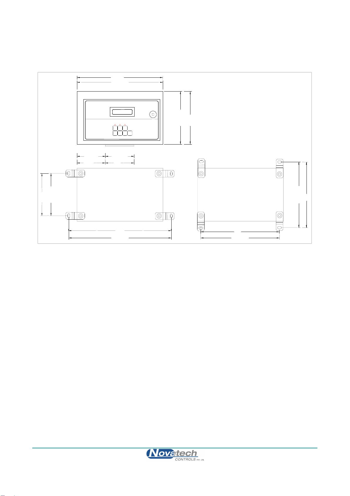
2.1 MOUNTING THE ANALYSER
Surface mount the analyser case on a flat surface or bracket, using the four mounting brackets provided.
Gland Plate
Vertical Mounting Brackets
Horizontal Mounting Brackets
150mm
280mm
180mm
225mm
250mm325mm
11"
7"
6"
12.8" 9.8"
9"
REAR VIEW
200mm
8"
40mm
1.6"
REAR VIEW
Case Mounting Dimensions
August 2009
14 1635 Water Vapour Analyser

2.2 INSTALLING THE OXYGEN PROBE
Weld a 1.5” BSP or NPT socket to the dryer or oven in a suitable position for sensing the water vapour level. The
closer to the source of moisture the smaller will be a sensing lag time, allowing better control.
The probe has a typical response time of less than four seconds, so most of the delay time is normally the transit time of
the gas from the point of moisture emission to the point of sensing.
It is necessary to angle the probe downward at about 20° minimum angle from horizontal, to avoid water vapour
building up in the probe housing. The sensing tip should be lower than the head.
Horizontal mounting requires
a minimum angle of 20° to
avoid water vapour
condensing at the cold end
Dryer or Oven
20°
REF
Installing an Oxygen Probe in the Dryer of Oven
2.3 INSTALLING THE RGS-01, REFERENCE GAS SENSOR
Screw the RGS-01 to a wall or similar surface with the piping connections at the bottom. Connect the gas sample
piping to the “sample in” port. The gas sample piping should be thin wall, 1/2” OD, stainless steel tube approximately
two metres long. It should rise vertically or at an angle of at least 20°from the horizontal.
SAMPLE IN
EXHAUST
1234 OXYGEN SENSOR
NOVATECH
CONTROLS
PUMP
WATER TRAP
SIGNAL WIRE GLAND
POWER SUPPLY GLAND
1/4"COLLECTOR TUBE
1/2" #20 SAMPLING TUBE
1231 PROBE
FLANGE
SAMPLING TUBE
Installation of the reference gas sensor
August 2009
1635 Water Vapour Analyser 15

August 2009
16 1635 Water Vapour Analyser
2.4 INSTALLING THE DRYER OR OVEN THERMOCOUPLE
Weld a 1/2 inch BSP mounting socket to the dryer or oven within about 300 mm, and upstream of the oxygen probe.
The thermocouple should be of similar length to the oxygen probe to prevent temperature distribution errors. The
thermocouple can be type ‘K’, ‘T’, or ‘J’.
This thermocouple is optional. It is only necessary when it is required to read the moisture content in % relative
humidity. This is not possible in direct fired applications using an RGS-01.
2.5 SHIELD CONNECTIONS
All external wiring to the 1635 analyser should be shielded. Do not connect shields at the field end. Simply clip off
and insulate. An extra terminal strip may be required to connect all shields together. This should be supplied by the
installer.

2.6 ELECTRICAL CONNECTIONS
All wiring should comply with local electrical codes. The printed circuit boards are fully floating above earth. All
earth and shield connections should be connected to the earth stud on the LHS inside the case. Before connection of
mains power check that the 115 / 230 volt power selector switch is set to the correct voltage.
21 RS-232 Tx
22 Network -
23
24
25
26 Output 1-
27 Output 2+
28 Output 2-
29 Common Alarm
30 Common Alarm
31 Alarm 2
32 Alarm 2
33 Alarm 3
34 Alarm 3
35 Alarm 4
36 Alarm 4
SENSOR #1
RGS-01
4-20mA Outputs
Selectable
ranges
Optional Alarm
Relay Contacts
Normally Closed
Mains Power Supply
240/115VAC
41
42
43 Cal 1 Sol
44 Cal 1 Sol
45 Cal 2 Sol
46 Cal 2 Sol
47 Mains E
48
49 Mains N
50 Mains A
Purge Sol
Purge Sol
51 Heater #1
52 Heater #1
White
White
White
White 53 Heater #2
54 Heater #2
Network +
Serial Common
Output 1+
Burner safety lock
or if safety interlock
not required link
terminals 18 & 19
Orange
Brown
Black
Blue
Black
Blue
Orange
Brown
Purge Flow Switch
Purge Flow Switch
Remote Alarm Reset
Remote Alarm Reset
Burner On Input
Burner On Input
RS-232 Rx
Fuel 1/2
18
19
20
15
16
17
Sens #2+
Sens #2-
Fuel 1/2
RGCI/P-
12
13
14
9
10
11
Probe TC+
Probe TC-
TC2/Aux+
TC2/Aux-
+12V
RGCI/P+
6
7
8
3
4
5
Probe +
Probe -
1
2
Connection Diagram for a 1635 Analyser, a 1231 Heated Probe and on optional RGS-01
August 2009
1635 Water Vapour Analyser 17

2.7 HEATER INTERLOCK RELAYSCAUTION
For direct fired dryers or ovens, explosion protection for heated probes is achieved by switching the power to the probe
heater off whenever the main fuel valve is closed. For indirectly heated ovens, connect a jumper bridge to terminals 18
and 19.
The principle of safety is that if the main fuel valve is open then main flame has been established. With this primary
source of ignition on, the probe heater can be safely switched on. The most dangerous situation is if fuel leaks into the
combustion appliance when the fuel valve is closed. When power is removed from the main fuel valve the heater
should also be switched off.
To achieve this protection, connect a main fuel valve voltage free contact to the ‘BURNER ON SWITCH’ terminals.
The contacts must be closed when the main fuel valve is open.
For installations where there is no risk of explosion, connect a jumper bridge to terminals number 18 & 19.
Burner on Switch
when main fuel valve is open
Contact must be closed
For Safety Interlock 18
19
Heater Supply Interlock Connection
2.8 CONNECTING THE OXYGEN PROBE CABLE
Connect the oxygen probe lead supplied as shown. Connect a 1/4” reference air tube from the analyser to the probe
‘ref’ connection.
C
B
A
F
D
E
G
O
rang
e
Black
Brown
B
lu
e
White
White
Main
Eart
1 Probe +
2 Probe -
3 Probe TC +
4 Probe TC -
S
hield
C
ommon
Term inal
G
reen
Probe
Therm ocouple
Probe
Heater
Probe
E a rth
O
th e
S
hield
Probe
Connector
Green
Yellow
(Shield
Sensor
Zirconia
Earth
(B y Installer)
51
52
Connection of Probe Cable for 1231 Model Heated Probes
August 2009
18 1635 Water Vapour Analyser
Table of contents
Other Novatech Measuring Instrument manuals


Popular Measuring Instrument manuals by other brands

Endress+Hauser
Endress+Hauser Viomax CAS51D operating instructions

Kane
Kane KANE3500 Series manual

Ahlborn
Ahlborn ALMEMO 2290-4 V5 operating instructions

VWR
VWR MD 8000 L manual

Seitron
Seitron PRESSOTEST 200 quick start guide

S+S Regeltechnik
S+S Regeltechnik PREMASREG 711 Series Operating Instructions, Mounting & Installation


