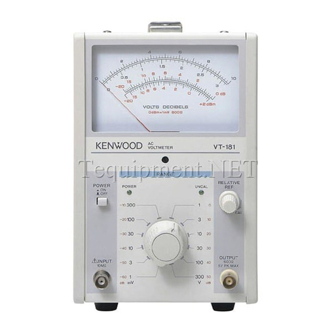
Kenwood VT-171 User manual

ACVOLTMETER
VT-171
VT-171E
©PRINTED
.
>APAN
INSTRUCTION
MANUAL
KENWOODCORPORATION
KENWOOD

CONTENTS
1.
GENERAL3
2.
FEATURES
3
3.SPECIFICATIONS4
4.
FUNCTIONALCONTROLS7
5.
OPERATION• 8
6.
APPLICATIONS10
7.
MAINTENANCE
12
8.
ALIGNMENT
13
9.
CAUTIONSFORUSE• ••14
A
product
of
KENWOODCORPORATION
2-5,
1
-chome
Shibuya,Shibuya-ku,Tokyo150,Japan
(2)

1.
GENERAL
2.
FEATURES
Your
KENWOOD'S
ElectronicVoltmeter,Model
VT-171,
r"VT-171EJ
, isa voltmeterofabsolute-meanvalue
indicationtypecapableofmeasuringACvoltages
from
ImVTSOO^VJ
to300Vr
100VJ
inthefrequency
rangeaswideas5Hzto1MHzonroot-mean-spuare
value
scales.
Your
VT-171
TVT-171EJ
isavailablein
varietyofapplicationsasitishighlysensitiveandresponds
accurately
togivenvoltagesinsucha widefrequency
range.
Foruseonproductionlines,itcanbecontrolled
bya remotecontroldevice(option).
This
manualooverstwomodels,
the
VT-171
and
VT-171E.
Mostdestdescriptionsarecommonto
both
models.
Where
therearedifferences,the descriptions for
the
VT-171E
areshownenclosed byT J.
a.
Dualpowerdifferential
input
amplifiersusedinthe
entirecircuitprovidea highreliabilityand
good
characteristic
ofrestoration
from
possiblesaturation
dueto
excessive
inputs.
b.A large-sizedTaut-bandmeterhasa highsensitivity
andreliability.
c.
Thenumberofadjustingtrimmersareminimized
with
theuseoftheamplifierswhichareprecisely
calculated
intheopen
loop
gainsandarenegative-
biased
through
metal-filmresistorsasaccurateas1%.
The
amplifiercharacteristics,therefore,arefree
from
any
secularchange.
d.
The
input
resistanceisashighas10MOinall
ranges
anditsparallelcapacitanceis45pForlower.
e.
Themeter
scales
aregraduatedintheroot-mean-
square
valuesforsinusolidal
waves.
Also,themeter
has
a dBanddBm
scales
convenientformeasuring
relative
values.
f.The
output
terminalallowsyour
VT-171
TVT-171EJ
touseasa high-gain,wide-bandamplifier.
<3>

9-
The
input
attenuatorsareswitchedbya so-called
"logic
control
circuit"so
that
a desiredrangecan
beselected
with
useofa
remote
control
device
(option).
h.
A
relayandFETswitchforrangeselection,
controlled
bythelogic
control
circuit,
provide
higher
reliability
thanusual
rotary
switchdirectswitching.
3.SPECIFICATIONS
[Meter
Section]
Messurablevoltages: 1mV-300mVin12ranges:1mV,3mV,
10mV,30mV,100mV,300mV,1V,3V,
10V,
30V,100V,and300V
full
scales.
ro.3mV-100mV
in12ranges:0.3mV,
1mV,3mV,10mV,30mV,100mV,
300mV,1V,3V,10V,30V,and100V
full
scales.J
dB
: ' -80~+50dB
r-90~+40dBJ
(0dB=1V)
dBm: -80~+52dBm
r-90~+42dBmJ
(0dBm=1mW,600O)
Error
: Within±3%of
full
scale
at1kHz.
Frequencyresponse: ±10%at5Hz-1MHz,
±5%at10Hz-500kHzand
±2%
at20Hz-100kHzas
referencedto1kHzresponse.
Input
impedance: 10MO± 5%,
with
less
than45pF
parallelcapacitance.
Durable
input
voltage: 500V(DC+ACpeak)
1V
to300Vr
100VJ
range
100V
(DC+ACpeak)
1mV
ro.3mVJ
to300mVrange

®
Stability: Within±0.5%of
full
scale
for
±10%linevoltagefluctuation.
Residual
voltage:
Less
than20^VF3Gj«VJ
with
input
shortedon1mV
TO.SmVJ
range.
[AmplifierSection]
Gain
: 60dB±1dB
T
Approx.
70dBJ
Output
voltage: 1Vrms±20%
Output
resistance: 60012± 20%
Frequency
response: Within±3dBat5Hz-500kHz.
Distortion:
Less
than1%at
full
scale.
(Rated
bysignal-noiseratioin
1mVand1Vranges.)
T
(Ratedbysigal-noiseratioin
0.3mV,1mVand1Vranges.)J
Signal-to-noiseratio: Over40dBat
full
scale.
rover30dBat0.3mVrange
J
[Environmental]
Temperature
coefficient: ± 0.08%/°C.
Within
specifications
tenperature: 10~40°C
Full
operating
temperature: 0~50°C
Relative
humidity
:
Less
than80%
[Power
SupplySection]
Line
voltage: 100,120,220VAC±10%,
216-250V
AC,50/60Hz
powerconsumption: Approx,4W.
[Dimensions]128(130)Wxl90(2l5)Hx238(260)Dmm.
Valuen
in( ) includeprotrusions.
[Netweight]2.9kg
[Accessories]
powercable: 1 pc.
Input
cable:
CA-41,
1 pc.
Replacement
fuse: 0.1A2
pes.
0.2A2 pes.
Instructionmanual: 1 copy.

Figure1-FrontPanelView. Figure2-RearPanelView.
<8>

4.FUNCTIONALCONTROLS
Figure3 - PresetControlsonSide
Panel.
1)FrontPanel(seeFigure1)
1.
Power-onindicator
2.
POWER
:
ON/OFF
switch
3.
RANGE
: Measurablevoltagerangeselector
switch
4.
INPUT,
10MO,:
Input
connector,10MOimpedance
5.
OUTPUT,
60012:
Output
connector,60012
impedance
6.
RELATIVE
REF: Relativereference
control
7.UNCAL: Uncalibrationindicator
8.Meter
9.
Meterzero-adjustscrew
2)RearPanel(seeFigure2)
10.
Powerconnector
11.
Linevoltageselectorandfuseholder
12.
Remote
control
connector
(option)
blind.
3)PresetControlsonSidePanel(seeFigure3)
The
following
controls,placedontheMainPCboard
(X65-1370-00),
aretobepresetonthe
right-hand
sidepanel.
13.
TC101: First
Attenuator
preset
trimmer
capacitor
14.
VR101: First
Attenuator
presetvariable
resistor
15.
VR102: MeterAmplifiergainpreset
variableresistor

5.OPERATION
•Set-up
1.
Press
the
ON/OFF
pushswitch©in,ThePower-on
indicator®,a
light-emitting
diode,
will
light,
indicatting
that
powerhasbeenapplied.
2.
Plugthemeasuringcable
into
theINPUTconnector
®.
3.
Setthe
RANGE
selector®to
"300V"T100VJ
.
To
measureanACvoltagesuperimpsedona DC
voltage,besuretosetthe
RANGE
selector(3)before
connectingthecabletoa
point
tobemeasured.
Otherwise,theDCvoltage
causes
a
high
surge,which
couldburnyourVT-171
TVT-171EJ
out.
4.
Connectthecabletothe
point
tobemeasure.
5.
Turnthe
RANGE
selector©
until
theMeterpointer
swings
overone
third
ofthe
full
scale.
6.
Read
theMeter.
(1)
Voltage
Scales
There
aretwoblackvoltage
scales
: a
scale
@ graduated
0to10anda
scale
®0to3.Whenthe
RANGE
selector
3
isat"1V",forexample,thedivision10onthe
scale
®indicates1V.Atthe"300mVposition,thedivision
3
onthe
scale
©indicates300mV.Similarly,theother
RANGE
selectorpositionsshowtheir
full
scale
values.
(2)dBScale
Ingeneral,thedBvaluesareexpressedindBVwhich
is
a
unit
referencedby0 dBequalto1V.Thedivision
10
atthe
scale
@ correspondsto0 dBonthedB
scale,
whichisa voltageratio
scale.
Sincethe
RANGE
selectorhas12rangepositionsinstepsof10dB,the
voltageratioof1mVro.3mVJto300Vr
100VJ
is110dB
attenuation.Assumea referencevoltagelevelonthe
scale
@ be1V
with
the
RANGE
selectorat" 1V"a given
voltagecanbereadaslowas-60dB(1mV)l~-70dB(0.3mV)
by
turning
theselectordownward.Further,asthe
scale
@
allowsreadingto-20dB(0.1mV)[~-20dB(0.03m
V)J,
youcancontinuoslymeasurethevoltageratioas
high
as
-80dB(0.1mVto1V)P-90dB(0.03mVto1V)J.Theread
of-80dBl~-90dBJmeansa signal-to-noiseratioof
around20dB
F~10dBJ.
Also,thedB
scale
allowscontinuous
measuringupto+50dB(1to300V)l~+40dB(1to
100V)J
by
turning
theselectorupward.
®

(3)
dBm
Scale
Ingeneral,voltmetershavea referenceleveldivision
ofOdBmequalto0.775V(1mVpower)inducedacross
a
600Oresistanceload.Therefore,thereddBm
scale
is
availabletomeasurea powerlevelreferencedto0
dBm,
with
theimpedanceofthegivenpowercircuit
being60012pureresistance.Wheremeasuredacross
specific
resistanceloads,forexample,10kOrother
thanthe600X1load,thelevelsaresometimes
expressed
indBs.
•HowtoUseRemoteControl
Availabilityofthe
optional
RemoteControlisoneof
outstandingfeaturesofyourVT-171
["VT-171EJ.
To
attachtheRemoteControl,removethe
blind
plate
attherearofyourVT-171
("VT-171EJ.
Installand
plug
the
optional
con-nector
into
the16-pinconnector
onthePCboard.
The
RT-61
option,
a remarkablefeatureofthe
VT-171,
providesa remote
control
capability.Tousethe
option,
removethe
case
andtherear-panel
blind
plate,install
theconnectorsupplied
with
the
RT-61,
then
plug
the
RT-61
into
the16-pinconnectoronthe
print
circuit
board.Fordetails,refertotheRT-61Instruction
Manual.
HowtoUseRelativeReferenceControl
The
RELATIVE
REF
control
iskeptat"CAL"in
general
cases
ofreadingcalibrated,absolutevalueson
theMeter.Tomeasurerelativelevelssuchasfre-
quencyresponses,
turn
the
control
foruncalibration
state(UNCAL)
until
thereferencelevelissettoa
desiredvalue,forexample,OdBm.Thisallowsreading
therelativelevels.
Figure
4-Meter
Scale
Graduations.
®

6.APPLICATIONS
The
basicuseofyour
VT-171
["VT-171EJ
istomeasure
sinusoidal
wavevoltagesasanACvoltmeter.Inaddition,
itprovidesa widevarietyofapplicationsasdescribed
below.
(1)AmplifierGainMeasurement
Your
VT-171
["VT-171EJ
iscapableofmeasuringan
amplifiergain,whichisa signalmagnification
from
point
A toB inFigure5
with
a signalgenerator
connectedtotheamplifier
input.
Ifthemeasured
signal
levelsatpointsA andB area andb dB,
respectively,
thenthegainis(b-a)dB.
Also,
themethodisapplicabletonegative-feedback
amplifiers;thatis,itisavailableformeasuringan
open
loop
gainofeachamplifiercircuit
with
the
negative-feedbacksignal
leaves
applied.
Further,
themethodcanbeusedformeasuringthe
frequencyresponsesofgivencircuitsbychangingthe
signal
generatorfrequency.
As
anexample,letuscalculatetheopen
loop
gain
(from
point
A toB)ofthenegative-feedbackamplifier
showninFigure6.Assumethatthemeasuredlevelat
point
A be+1.5dBinthe-60dBrangeandthatof
point
B -4dBinthe+10dBrange.Thegain
from
point
A
toB is
(+l0dB-4dB)-(-60dB
+ 1.5dB)= 64.5dB.
SIGNAL
GENERATOR
Figure
5-AmplifierGainMeasurement.
SIGNAL
GENERATOR
Figure
6-NegatveFeedbackAmplifierGainMeasurement.
®

(2)Root-Mean-SquareandPeakValueCalculations
Your
VT-171
FVT-171EJ,
anvoltmeterofabsolute-mean
value
indicationtype,readsroot-mean-squarevaluesof
sinusoidalwaveinputs.Also,itdeflectsthe
pointer
in
proportion
totheabsolute-meanvalueofa given
input
wave.
Ifthe
form
factor(=root-mean-squarevalue/absolute
meanvalue)ofthe
input
waveandthecrest(= peak
value/root-mean-squarevalue)areknown,thenthe
root-mean-squarevalueandpeakvaluecanbe
cal-
culatedasfollows.
a.
Assume
that
themeterreadsV.
2\Tl
•Absolutemeanvalue=• V ^ 0.9V.
TZ
•Root-mean-squarevalue=(Absolutemeanvalue)
x(formfactor).
•
Peak
value=(Root-mean-squarevalue)x (crest).
b.Forrectangular
waves,
their
form
factoris
unity
(1)
andthecrestunit(1).
2v/~2~
•Absolutemeanvalue=-V^0.9V.
7C
•
Peak
value=0.9V.
c.
Forsawtooth
waves,
their
form
factoris2/v/3_and
thecrest
\/3".
•Absolutemeanvalue= V ^ 0.9V.
7T
•Root-mean-squarevalue=
x
-=V=
--^-V^
1.04V.
•
Peak
value=-^x^—1.8V.
7TV3 %

7.MAINTENANCE
(1)
Removingthecasing(seeFigure7)
1.
Removethesixscrews
holding
thecasingonthe
both
sidesandtopusinga Phillipsscrewdriver.
2.
Widenthe
bottom
ofthe7-shapedcasinga
little
and
pull
itupforremoval.
(2)
Mounting
thecasing(seeFigure8)
1.
Widenthe
bottom
ofthecasinga
little
when
coveringitoverthemainbody.
2.
FitthecasingPCboardretianertothePCboard
retainer.
3.
Alternately
tighten
thesixscrewsfor
uniform
torque.
(3)Replacingthefuse(seeFigure9)
REPLACING
FUSE
Whena fusegoesout,thedeviceisnolongeroperable.
Ifgoneout,checkfora
trouble
cause,
remedyit,remove
thecapofthefuseholderontherearpanelusinga
minusscrewdriverandtakeitoutandreplacethefuse
with
a newone.
Whenreplacingfuse,be
sura,
tocheckthecapacityofa
newfusefora specifiedvalueasfollows:
AC
100V,120: 0,2A
AC
220V,240V : 0.1A
CHANGEOVER
OF
VOLTAGE
IN
SWITCHING
REGULATOR
Remove
thefuseholderontherearsidedeviceset,
usinga minussurewdriver,adjustyourpreferred
voltageindication
with
T markand
plug
theholderin.
For
changing100Vor120Vto220Vor240V,change
thefuseof0.2Ato
that
of0.1A.
Figure
7-CasingRemoval.
CASING
MOUNTING
SCREWS,
6
PIECES

Figure
8-PCBoardRetainer,
Figure
9-Replacingthee.
8.ALIGNMENT
Your
VT-171
waspreciselypresetatthefactory.How-
ever,
itcanbealignedthroughtheadjustholeslocated
ontheright-handsidewithleavingithousedinthe
casing,
ifrequired.Inrealignment,firstadjusttheline
voltagetothevoltage,usea preciselycalibratedmeasur-
inginstruments,andproceedasfollows
(also,
seeFigures
1
through3).
1.
Beforeturningthe
ON/OFF
switch"ON",adjustthe
Meterzero-adjustscrew
until
thepointercorrectly
indicates
"0".
2.
Connecta voltmetercalibrator
1
kHz(or400Hz)
output
tothe
INPUT
connector®.
3.
Setthevoltmetercalibrator
output
voltageto30mV
and
setthe
RANGE
selector© onyour
VT-171
I~VT-
171EJ
tothe"
30m
V"
range.
4.
Adjust
VR102
until
thepointerswingstothe
full
scale.
5.
Inturn,setthevoltmetercalibrator
output
voltageto
10V
andsetthe
RANGE
selector3 tothe"10V"range.
6.
AdjustVR101
until
thepointerswingstothe
full
scale.
7.
Disconnectthevoltmetercalibratorandconnecta

wide-bandsignalgeneratortothe
INPUT
connector®.
8.
Setthesignalgeneratorfrequencyto
1
kHzandset
the
RANGE
selector© onyour
VT-171
[""VT-171EJ
to
the"1V"range.
9.
Adjustthesignalgenerator
output
voltage
until
the
pointerswingstothe
full
scale.
10.
Changethesignalgeneratorfrequencyfrom
1
kHzto
50kHz.
11.
AdjustTC101
until
thepointerswingstothe
full
scale.
12.
Repeat
Steps
2 through11.
®
9,CAUTIONSFORUSE
1.
Your
VT-171
TVT-171EJ
willworkjustwhenthe
POWER
switchispressedin.Foraccuratemeasure-
ments,
waitaroundfiveminutesforwarm-up.
2.
Avoidplacingyour
VT-171
fVT-171
EJ
wheremagnetic
fieldandelectricfieldaretoostrong.
3.
Theinputcableotherthanthesuppliedoneshouldbe
low-capacitance
shieldedcord,orcoaxialcable.
4.
Thecontinuousmaximuminputvoltageallowablefor
your
VT-171
FVT-171EJ
is100V(DC+ACpeak)with
the
RANGE
selectorat"~60dB
l~-70dBJ
"to"-10dB
["-lOdBJ
".Fullcareshouldbeodservedinmeasuring
highvoltages.
5.
Becarefulofa linenoiseandsimilarsmallnoisesas
your
VT-171
fVT-171EJ
isa highlysensitivevoltmeter.
6.
Donotleaveyour
VT-171
TVT-171EJ
atanyofhigh
temperatureandhumidityplacesfora longperiodof
time.
7.
The
ON/OFF
switchof
thit
isdesignedtoactonthe
secondary
sideofthepowertransformer.Theprimary
side
ofthetransformerremainsenergizedevenifthe
ON/OFF
switchissetto
OFF.Therefore,
iftheunit
is
tobeunusedfora longtime,thepowercordshould
beunplugged: n thereceptacleoutlet.
This manual suits for next models
1
Table of contents
Other Kenwood Measuring Instrument manuals

Kenwood
Kenwood FC-757 User manual

Kenwood
Kenwood MS-1660 User manual

Kenwood
Kenwood VT-175 User manual

Kenwood
Kenwood DM-81 User manual

Kenwood
Kenwood HM-250 User manual

Kenwood
Kenwood FL-180 User manual

Kenwood
Kenwood FL-180A User manual

Kenwood
Kenwood VT-172 User manual

Kenwood
Kenwood VT-173 User manual

Kenwood
Kenwood VT-176 User manual