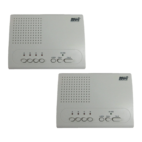
Novi DB-301 User manual

Black 0001
Black0001
Doorbell Intercom
Security System
Installation Guide
Model DB-301
LOCK CALL TAL K
ABC
OFF
POWER IN USE
™
By Linear
™
By Li near
INSTR,INSTL,DB-301,ENGLISH
Linear P/N: 216082 B
Size: 5.500" x 8.500"
Material: 60 Lb. White Coated with 80 Lb. White Coated Cover
Ink: Black
Scale: 1-1

Black 0002
Black0002
EXPLANATION OF GRAPHIC WARNING SYMBOLS
This symbol is intended to alert the user to the
presence of un-insulated “dangerous voltage”
within the product’s enclosure that may be of
sufficient magnitude to constitute a risk of electric
shock.
This symbol is intended to alert the user to the
presence of important operating and maintenance
(servicing) instructions in the literature
accompanying the device.
✶
WARNING! To prevent fire or shock
hazard, do not expose this device to
rain, water, or wet locations.
✶
CAUTION! To prevent electric shock,
match wide blade of plug to wide slot,
fully insert.
IMPORTANT SAFETY NOTES
☞
POWER SOURCE This unit should only be connected to a 110-120 VAC
power source as marked on the unit.
☞
GROUNDING OR POLARIZATION This unit is equipped with a polarized
AC power cord plug (a plug having one blade wider than the other). This
plug will fit into the power outlet only one way. This is a safety feature. If
you are unable to insert the plug fully into the outlet, try reversing the plug.
If the plug still fails to fit, contact your electrician to have a suitable outlet
installed. Do not defeat the safety purpose of the polarized plug.
☞
NON-USE PERIODS Always turn the unit off and unplug when it is not being
used or left unattended for long periods of time.
☞
OBJECT AND LIQUID ENTRY Never push objects of any kind into the unit
through the cabinet slots as they may touch dangerous voltage points or
short out parts that could result in a fire or electric shock. Never spill liquid
of any kind on the unit.
☞
CLEANINGUnplug theunit fromthe wall outletbefore cleaningorpolishing
it. Do not use liquid cleaners, aerosol cleaners, gasoline or other flammable
fluid. Clean the exterior of the unit with a slightly damp cloth.
☞
WATER AND MOISTURE Do not use power line operated units near water
- for example, near a bathtub, washbowl, kitchen sink, or laundry tub, in a
wet basement, or near a swimming pool.
☞
VENTILATION The appliance should be situated so that its location or
position does not interfere with its proper ventilation. For example, the unit
should not be situated on a bed, sofa, rug or placed in a built-in installation
that may block the flow of air through the ventilation openings.
CAUTION
RISK OF ELECTRIC SHOCK
DO NOT OPEN
CAUTION: TO REDUCE THE RISK OF ELECTRIC SHOCK
DO NOT REMOVE COVER (OR BACK)
NO USER-SERVICEABLE PARTS INSIDE
REFER SERVICE TO QUALIFIED PERSONNEL
INSTR,INSTL,DB-301,ENGLISH
Linear P/N: 216082 B
Size: 5.500" x 8.500"
Material: 60 Lb. White Coated with 80 Lb. White Coated Cover
Ink: Black
Scale: 1-1

Black 0003
Black0003
☞
POWER CORD PROTECTION Power supply cords should be routed so
that they are not likely to be walked on or pinched by items placed upon or
against them paying particular attention to cords at plugs, convenience
receptacles, and the point where they exit from the appliance.
☞
READ INSTRUCTIONS All the safety and operating instructions should be
read before the product is operated.
☞
RETAIN INSTRUCTIONS The safety and operating instructions should be
retained for future reference.
☞
HEED WARNINGS All warnings on the product and in the operating
instructions should be adhered to.
☞
FOLLOW INSTRUCTIONS All operating and use instructions should be
followed.
☞
ATTACHMENTSDonotuseattachmentsnotrecommendedbytheproduct
manufacturer as they may cause hazards.
☞
ACCESSORIESDonotplacethisproductonanunstablecart,stand,tripod,
bracket, or table. The product may fall, causing serious injury to a child or
adult,andseriousdamagetotheproduct.Useonlywithacart,stand,tripod,
bracket or table recommended by the manufacturer, or sold with the
product. Any mounting of the product should follow the manufacturer’s
instructions, and should use a mounting accessory recommended by the
manufacturer.
☞
OVERLOADING Do not overload wall outlets, extension cords, or integral
convenience receptacles as this can result in a risk of fire or electric shock.
☞
REPLACEMENT PARTS When replacement parts are required, be sure
the service technician has used replacement parts specified by the
manufacturer or have the same characteristics as the original part.
Unauthorized substitutions may result in fire, electric shock, or other
hazards.
☞
SAFETYCHECK Uponcompletionofanyserviceorrepairstothisproduct,
ask the service technician to perform safety checks to determine that the
product is in proper operating condition.
☞
WALL OR CEILING MOUNTING The product should be mounted to a wall
or ceiling only as recommended by the manufacturer.
☞
HEAT The product should be situated away from heat sources such as
radiators,heatregisters,stoves,orotherproducts(includingamplifiers)that
produce heat.
INSTR,INSTL,DB-301,ENGLISH
Linear P/N: 216082 B
Size: 5.500" x 8.500"
Material: 60 Lb. White Coated with 80 Lb. White Coated Cover
Ink: Black
Scale: 1-1
1

Black 0004
Black0004
SERVICE NOTES
☞DAMAGE REQUIRING SERVICE Unplug the unit from the
wall outlet and refer servicing to qualified service personnel
under the following conditions.
➦If liquid has been spilled into the unit.
➦If the unit has been exposed to water.
➦If the unit has been dropped, enclosure, cord, or plug
damaged.
➦If the unit does not operate normally when following
the operating instructions.
➦When the unit exhibits a distinct change in
performance.
THE USER SHOULD NOT ATTEMPT TO SERVICE THE
UNIT. ALL SERVICING SHOULD BE REFERRED TO
QUALIFIED PERSONNEL.
Changes or modifications to the unit may void the
users authority to operate the equipment.
DOORBELL INTERCOM SYSTEM FEATURES
❐Allows you to answer your door without ever opening your door.
❐Allows you to answer your door from any room in your house.
❐Easily converts any doorbell into a complete in-home intercom and
security system.
❐Provides safety, security and peace of mind.
❐Easy to install and operate.
☞
NOTE:
“WIRELESS TECHNOLOGY” can infer sound transmission is
carried on the airwaves or through the electrical wiring of your home or
business. Linear Wireless Intercom Products have sound carried on the
electrical wiring. The wiring in your building must be able to complete an
electrical loop without any interference. This means that the electrical line
coming from the transformer outside your building, will enter your building,
loop through each roomand exit at the same point where it entered. If there
has been an added loop brought in, remodeling done, or a sub-transformer
is present, transmission may not be possible.
W ire C u tte r
P h illip s H e a d
S c re w d riv e r
FlatH ead
S c re w d riv e r
D rill
(M ay notbe
re q u ire d )
18 AW G BellW ire
ElectricalTape
WireNuts
R E Q U IR E D T O O L S
INSTR,INSTL,DB-301,ENGLISH
Linear P/N: 216082 B
Size: 5.500" x 8.500"
Material: 60 Lb. White Coated with 80 Lb. White Coated Cover
Ink: Black
Scale: 1-1
2

Black 0005
Black0005
CONTENTS
Thank you for your purchase of the Linear Doorbell Intercom Security
System. Linear is proud to bring to the public an easy-to-install and use
in-home security and communications system. By using your home’s
electrical wiring to carry sound, the Doorbell Intercom Security System
offers you the opportunity to answer the door from any electrical outlet
on your property.* In addition to the convenience that this product
brings, you will also appreciate the security feature, that makes it
possible to talk to people outside your door, without actually opening it.
*This occurs if all outlets around the property are connected to the same
electrical loop that the household wiring is on. Most homes in the U.S.
will have only one electrical loop on the property.
For technical assistance
Call: 1-800-842-5378
DOORBELL INTERCOM SECURITY SYSTEM . . . . . . . . . . . . . . 4
Wireless Intercom . . . . . . . . . . . . . . . . . . . . . . . . . . . 5
Doorbell Module . . . . . . . . . . . . . . . . . . . . . . . . . . . . 5
DOORBELL MODULE INSTALLATION . . . . . . . . . . . . . . . . . . 6
Installing Using Existing Doorbell Wiring . . . . . . . . . . . . . . . . 6
Installing As A New Independent System . . . . . . . . . . . . . . . 8
INTERCOM INSTALLATION . . . . . . . . . . . . . . . . . . . . . . . 10
TESTING THE SYSTEM . . . . . . . . . . . . . . . . . . . . . . . . . 10
TROUBLESHOOTING . . . . . . . . . . . . . . . . . . . . . . . . . . 11
No Sound . . . . . . . . . . . . . . . . . . . . . . . . . . . . . . . 11
Poor Sound Quality . . . . . . . . . . . . . . . . . . . . . . . . . . 11
SPECIFICATIONS . . . . . . . . . . . . . . . . . . . . . . . . . . . . 12
INSTR,INSTL,DB-301,ENGLISH
Linear P/N: 216082 B
Size: 5.500" x 8.500"
Material: 60 Lb. White Coated with 80 Lb. White Coated Cover
Ink: Black
Scale: 1-1
3

Black 0006
Black0006
DOORBELL INTERCOM SECURITY SYSTEM
LOCK CALL TAL K
ABC
OFF
POWER IN USE
™
By Linear
1
7
8
WI-3P
3-CHANNEL INTERCOM
DB-300
DOORBELL MODULE
™
By Linear
OFF
910
12
13
11
24
356
INSTR,INSTL,DB-301,ENGLISH
Linear P/N: 216082 B
Size: 5.500" x 8.500"
Material: 60 Lb. White Coated with 80 Lb. White Coated Cover
Ink: Black
Scale: 1-1
4

Black 0007
Black0007
Wireless Intercom
1. IN USE & POWER INDICATORS
Lights when intercom is activated, lights when
AC power is on.
2. POWER/VOLUME SWITCH
Turns unit on and off, controls volume.
3. CHANNEL SELECTOR
Allows you to select between channels.
4. LOCK BUTTON
Press down for continuous monitoring. (Used only
when communicating between two or more wireless
intercoms.)
5. CALL BUTTON
Pages other units on the same channel. (Used only
when communicating between two or more wireless
intercoms.)
6. TALK BUTTON
Press to talk. Release to listen.
7. MICROPHONE
High-gain microphone monitors your voice.
8. SPEAKER
Clearly transmits pure, static-free, two-way voice
communication.
Doorbell Module
9. DOORBELL BUTTON
Produces a doorbell sound.
10. TALK BUTTON
Press to talk, Release to listen
11. CHANNEL SELECTOR
Allows you to select between channels.
12. WIRE TERMINALS
Used to connect transformer to doorbell.
13. RETAINING SCREW
Secures doorbell module to mounting plate.
INSTR,INSTL,DB-301,ENGLISH
Linear P/N: 216082 B
Size: 5.500" x 8.500"
Material: 60 Lb. White Coated with 80 Lb. White Coated Cover
Ink: Black
Scale: 1-1
5

Black 0008
Black0008
DOORBELL MODULE INSTALLATION
Installing Using Existing Doorbell Wiring
1. In a typical household doorbell system,
the three components (doorbell button,
doorbell and doorbell transformer) are
wired in a loop (see figure).
✶
WARNING! Before proceeding, turn
offthe circuitbreaker(orremovefuse)
that supplies current to your existing
doorbell transformer. Press the
doorbell button to double check that
the power is off.
2. Remove and disconnect existing
doorbell button.
3. Attachdoorbell-mountingbrackettowall
using the two screws provided.
4. Setdoorbellmodulechannelswitchesto
select intercom channel. For Channel
“A” set Switch 1 ON and Switch 2 OFF.
For Channel “B” set Switch 1 OFF and
Switch 2 ON.
5. Connect existing wires to terminals on
doorbell module (either wire to either
terminal).
TYPICAL HOUSEHOLD
DOORBELL
DOORBELL
BUTTON
DOORBELL
DOORBELL
TRANSFORMER
DISCONNECT AND REM OVE
EXISTING DO ORBELL BUTTON
MOUNT BRACKET
TO WALL USING
TWO SCREWS
PROVIDED
SET CHANNEL
SWITCH
CHANNEL "A"
Switch 1 ON
Switch 2 OFF
CHANNEL "B"
Switch 1 OFF
Switch 2 ON
1 2
1 2
CONNECT WIRES
TO TERMINALS
(EITHER WIRE TO
EITHER TERMINAL)
INSTR,INSTL,DB-301,ENGLISH
Linear P/N: 216082 B
Size: 5.500" x 8.500"
Material: 60 Lb. White Coated with 80 Lb. White Coated Cover
Ink: Black
Scale: 1-1
6

Black 0009
Black0009
6. Attach doorbell module to doorbell
mounting bracket (secure with retaining
screw later after adjusting volume).
7. Disconnect low-voltage (24 VAC)
interior wires from existing doorbell
transformer.
8. Disconnect the two wires inside the
doorbell and twist them together.
Secure and insulate wires with a wire
nut.
9. Route 18 AWG bell wire from the
location of the wires disconnected in
Step 7 to a nearby 110 VAC outlet
location.
10. Connect existing wires to the 18 AWG
bell wire with two wire nuts.
11. Connect the other end of the 18 AWG
bell wire to the AC adapter terminals
(either wire to either terminal).
ALIGN TOP
EDGE FIRST
SWING
CLOSED
SECURE WITH
RETAINING SCREW
REMOVE WIRES FROM
SECONDARY SIDE OF
DOORBELL TRANSFORMER
REMOVE WIRES
FROM TERMINALS
TWIST WIRES TOGETHER
AND SECURE WITH WIRE NUT
USE 18 AWG BELL WIRE
BETWEEN EXISTING
DOORBELL WIRE AND
110 VAC OUTLET
WIRE LEADING
TO OUTLET
LOCATION
EXISTING
DOORBELL
WIRES
CONNECT WIRES
TO TERMINALS
(EITHER WIRE TO
EITHER TERMINAL)
INSTR,INSTL,DB-301,ENGLISH
Linear P/N: 216082 B
Size: 5.500" x 8.500"
Material: 60 Lb. White Coated with 80 Lb. White Coated Cover
Ink: Black
Scale: 1-1
7

Black 0010
Black0010
12. A DB-301 system wired using the
existing doorbell wiring will be set up as
shown in the figure.
13. Plug adapter into an unswitched 110
VAC power outlet. Turn on circuit
breaker (or replace fuse) to restore
power to other devices on that circuit.
Installing As A New Independent System
1. Attachdoorbell-mountingbrackettowall
using the two screws provided.
2. Drill holes to provide wiring access
from doorbell-mounting bracket to a
nearby 110 VAC power outlet.
3. Route 18 AWG bell wire from doorbell-
mounting bracket to 110 VAC outlet
location.
PLUG AC ADAPTER
INTO UNSWITCHED
110 VAC OUTLET
INSIDE
WALL
OUTSIDE
WALL
HOLE
HOLE
18 AWG
BELL WIRE
MOUNT BRACKET
TO WALL USING
TWO SCREWS
PROVIDED
DB-300
AC-12C
INSTR,INSTL,DB-301,ENGLISH
Linear P/N: 216082 B
Size: 5.500" x 8.500"
Material: 60 Lb. White Coated with 80 Lb. White Coated Cover
Ink: Black
Scale: 1-1
8

Black 0011
Black0011
4. Setdoorbellmodulechannelswitchesto
select intercom channel. For Channel
“A” set Switch 1 ON and Switch 2 OFF.
For Channel “B” set Switch 1 OFF and
Switch 2 ON.
5. Connect wires to terminals on doorbell
module (either wire to either terminal).
6. Attach doorbell module to doorbell-
mounting bracket (secure with retaining
screw later after adjusting volume).
7. Connect wires to AC adapter terminals
(either wire to either terminal).
8. Plugthe adapterinto anunswitched 110
VAC power outlet.
CONNECT WIRES
TO TERMINALS
(EITHER WIRE TO
EITHER TERMINAL)
ALIGN TOP
EDGE FIRST
SWING
CLOSED
SECURE WITH
RETAINING SCREW
CONNECT WIRES
TO TERMINALS
(EITHER WIRE TO
EITHER TERMINAL)
PLUG AC ADAPTER
INTO UNSWITCHED
110 VAC OUTLET
SET CHANNEL
SWITCH
CHANNEL "A"
Switch 1 ON
Switch 2 OFF
CHANNEL "B"
Switch 1 OFF
Switch 2 ON
1 2
1 2
INSTR,INSTL,DB-301,ENGLISH
Linear P/N: 216082 B
Size: 5.500" x 8.500"
Material: 60 Lb. White Coated with 80 Lb. White Coated Cover
Ink: Black
Scale: 1-1
9

Black 0012
Black0012
INTERCOM INSTALLATION
1. Choose where you want to plug in the
wireless intercom that is being used as
a doorbell. Make sure that the channel
selector on each of the intercoms you
install are on the same channel as the
doorbell module. We recommend that
you dedicate at least one intercom per
floor. (Do not change the channel
position on dedicated intercoms after
you have installed the system).
2. Locate the volume control screw on the
backofthedoorbellmodule.Useasmall
Phillips-head screwdriver to raise or
lowervolume.Toincreasethevolumeof
doorbell module, turn screw counter
clockwise.
TESTING THE SYSTEM
Make sure doorbell module AC adapter is plugged in and that Wireless
Intercom is plugged in. You should see light shining through both
buttons on the front of the doorbell module. This indicates power is
present.
1.
Ask someone to assist you. One person should stand at door,
while second person stands next to the Intercom.
2.
Person at door should press DOORBELL button. This should
produce a doorbell sound.
3.
Person at intercom should now press and hold down TALK
button and speak to the person at doorbell. Then release to wait
for reply.
4.
The person at door should now press TALK and answer back.
5.
To continue conversation, simply press TALK button back and
forth between the two locations, remembering to release the
buttons when waiting for a reply.
6.
If the sound is good, you may now replace the retaining screw.
The LOCK and CALL buttons on the wireless intercom have no practical
use in the doorbell application. They are used only when communicating
between two or more wireless intercoms. You may purchase additional
wireless intercoms to create an in-home communication system. You
would use whatever channel or channels that have not been assigned
to the Doorbell Intercom Security System. Remember that the wireless
intercoms assigned to the Doorbell Intercom System are dedicated and
should not be used for any other purpose.
VOLUME
CONTROL
INCREASE DECREASE
PLUG INTERCOM
INTO 110 VAC
OUTLET
INSTR,INSTL,DB-301,ENGLISH
Linear P/N: 216082 B
Size: 5.500" x 8.500"
Material: 60 Lb. White Coated with 80 Lb. White Coated Cover
Ink: Black
Scale: 1-1
10

Black 0013
Black0013
TROUBLESHOOTING
No Sound ☞Check to see if channel selection is the same on doorbell
module and wireless intercom.
☞Make sure LOCK button on wireless intercom is up.
☞Make sure wireless intercom is turned on and volume control
is up.
☞Makesurevolumecontrolonbackofdoorbellmoduleisturned
up.
☞Make sure the light shines through on both buttons on front of
doorbell module, if the lights are not there, this means
electricity is not reaching the module. Check to see if wires
connecting doorbell module and AC adapter are firmly
connected. Make sure that AC adapter is plugged into outlet
and that there is electricity at outlet.
☞You may have damaged wire connecting the doorbell module
and AC adapter. Reconnect doorbell module and AC adapter
with good wire.
☞You may have more than one electrical loop. Try moving
wireless intercom to other outlets around your home to see if
any connect with the electrical line the adapter is plugged into.
If all of the above have been tried withoutsuccess, disconnect
adapter and doorbell module and reconnect with a few feet of
wire. Plug adapter into an outlet and plug wireless intercom
into same outlet. If both units are on the same channel, but do
not communicate, call the telephone number on the enclosed
warranty card.
Poor Sound Quality
☞Fluorescent lights, computers, base units of cordless phones
and touch-activated appliances may cause a scratchy or
broken signal. The strength of Linear filters is superior to most
other intercoms; however, modern consumers are adding
more technologically advanced products to their household
current, some of these products may cause electrical
interference. Please try the following steps to determine if
improvement is possible.
1.
Change channel on back of doorbell module and on
wireless intercom.
2.
Plug wireless intercom into different outlets around the
property.
3.
You may have a loose connection. Check all terminals
and wire.
INSTR,INSTL,DB-301,ENGLISH
Linear P/N: 216082 B
Size: 5.500" x 8.500"
Material: 60 Lb. White Coated with 80 Lb. White Coated Cover
Ink: Black
Scale: 1-1
11

Black 0014
Black0014
SPECIFICATIONS
DESCRIPTION SPECIFICATION
DOORBELL MODULE
POWER SOURCE 12 VAC AT 60 Hz
CARRIER FREQUENCY (A) 230 kHZ, (B) 260 kHz
RF OUTPUT POWER 80 mW (70 mW - 100 mW)
AUDIO OUTPUT POWER 500 mW
STANDBY CURRENT 30 mA
MAXIMUM CURRENT 180 mA
DIMENSIONS 3" x 5-1/4" x 1-1/4"
WEIGHT 8-1/4 oz
3-CHANNEL WIRELESS INTERCOM
POWER SOURCE 110-120 VAC AT 60 Hz
CARRIER FREQUENCY (A) 230 kHz, (B) 260 kHz (C) 290 kHZ
RF OUTPUT POWER 100 mW
AUDIO OUTPUT POWER 500 mW
MODULATION METHOD FREQUENCY MODULATION (FM)
TRANSMIT/RECEIVE PHASE LOCKED LOOP (PLL)
DIMENSIONS 6" x 5" x 1"
WEIGHT 1 Lb.
INSTR,INSTL,DB-301,ENGLISH
Linear P/N: 216082 B
Size: 5.500" x 8.500"
Material: 60 Lb. White Coated with 80 Lb. White Coated Cover
Ink: Black
Scale: 1-1
12

Black 0015
Black0015
INSTR,INSTL,DB-301,ENGLISH
Linear P/N: 216082 B
Size: 5.500" x 8.500"
Material: 60 Lb. White Coated with 80 Lb. White Coated Cover
Ink: Black
Scale: 1-1

Black 0016
Black0016
Copyright © 1999 Linear Corporation 216082 B
INSTR,INSTL,DB-301,ENGLISH
Linear P/N: 216082 B
Size: 5.500" x 8.500"
Material: 60 Lb. White Coated with 80 Lb. White Coated Cover
Ink: Black
Scale: 1-1
Table of contents
Other Novi Intercom System manuals