Novus NR2306-O-G User manual

USERS MANUAL
NR2306-O/G
REVISION
A
DATE
3-8-18
Page | 1
NR2306-O-G
10 MHz Six Channel Ultra Low Noise GNSS Locked
Frequency Reference
All information provided herein is the property of Novus Power Products LLC. The information
included may be reproduced without the permission of Novus Power Products LLC for the
purpose of operating the Novus equipment.

USERS MANUAL
NR2306-O/G
REVISION
A
DATE
3-8-18
Page | 2
Contents
1.0 Overview...................................................................................................................... 3
2.0 Controls and Indicators –Front Panel............................................................................... 6
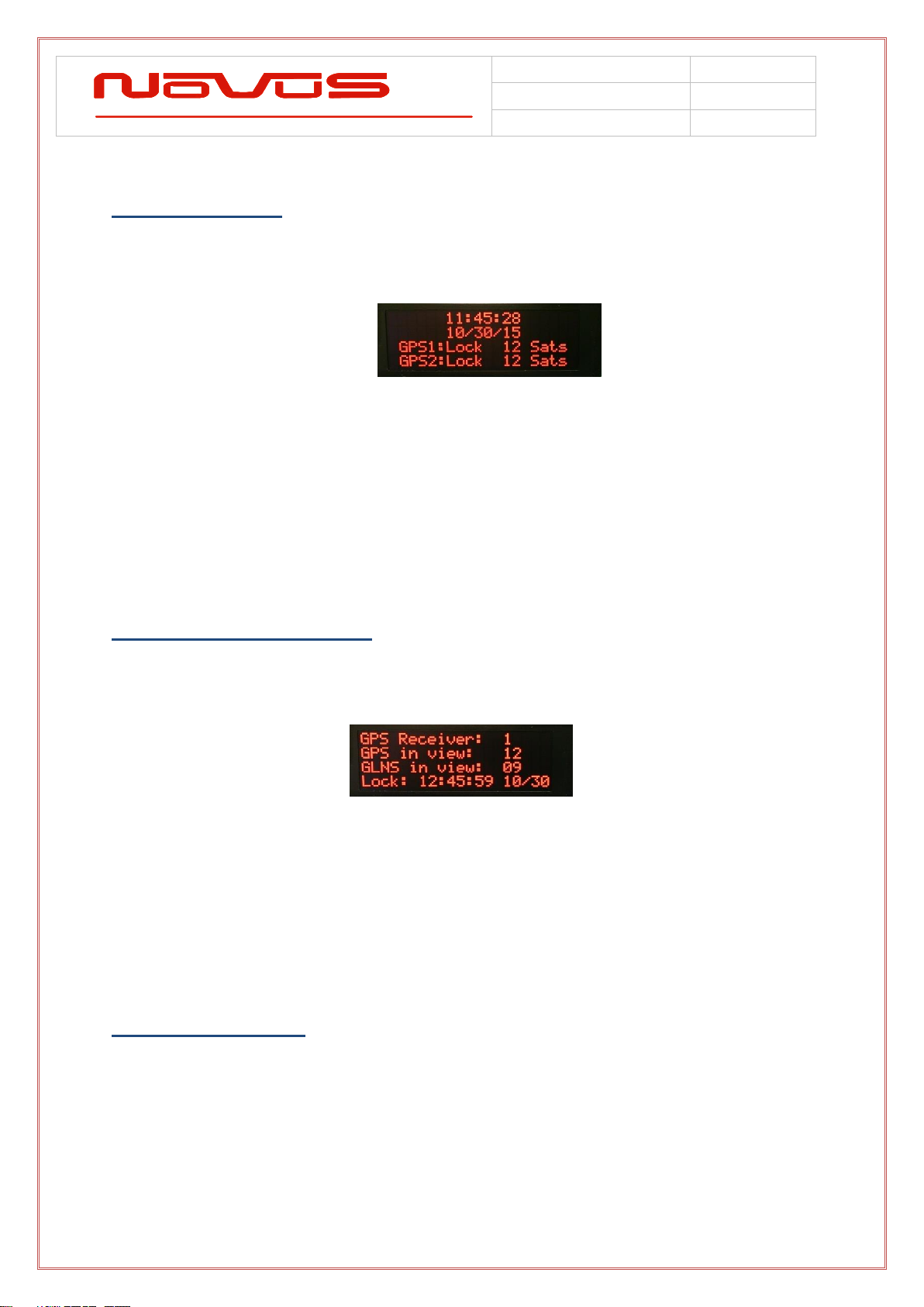
2.1 GNSS Status....................................................................................................................... 7
2.2 GNSS Detailed Status.......................................................................................................... 7
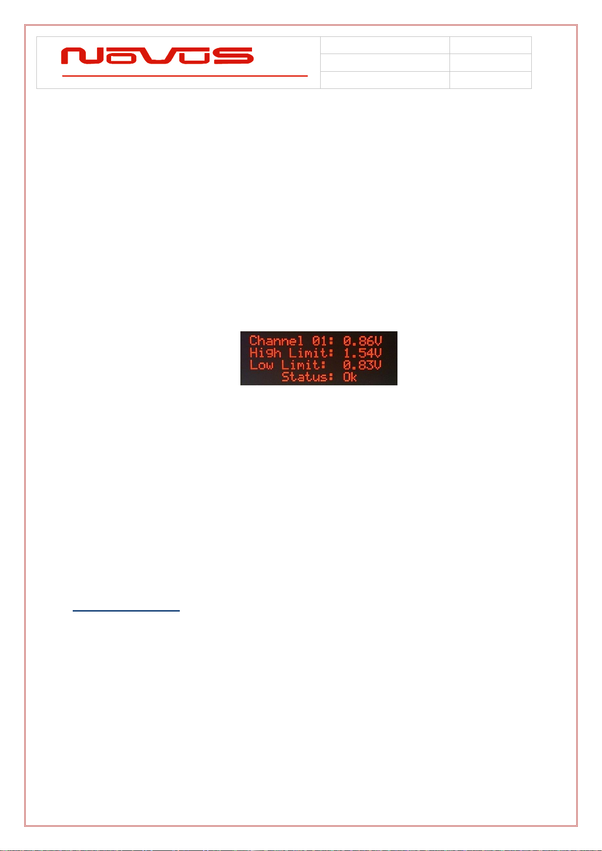
2.3 Channel Status ................................................................................................................... 7
2.4 Status LEDs........................................................................................................................ 8
2.5 Alert Threshold................................................................................................................... 9
2.6 Latch Channel Values.........................................................................................................11
2.7 PPS Status ........................................................................................................................11
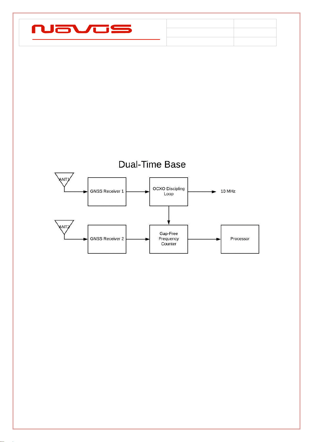
2.8 GPS Select (Dual Time Base Feature) .................................................................................13
2.9 Save Configuration ............................................................................................................14
2.10 Fault Status.....................................................................................................................14
2.11 UTC Mode .......................................................................................................................15
2.12 GMT Offset......................................................................................................................15
2.13 Power Switch...................................................................................................................16
3.0 Rear Panel .................................................................................................................. 16
3.1 Channel Outputs - BNC ......................................................................................................16
3.2 Antenna Input A/B - SMA ...................................................................................................16
3.3 DC Input...........................................................................................................................17
3.4 AC Input ...........................................................................................................................17
4.0 GNSS Receiver............................................................................................................. 17
5.0 Antenna...................................................................................................................... 19
6.0 Programming Guide (RS232 Port) .................................................................................. 20
6.1 RS232 / Status / Command ................................................................................................21
Specifications .................................................................................................................... 22
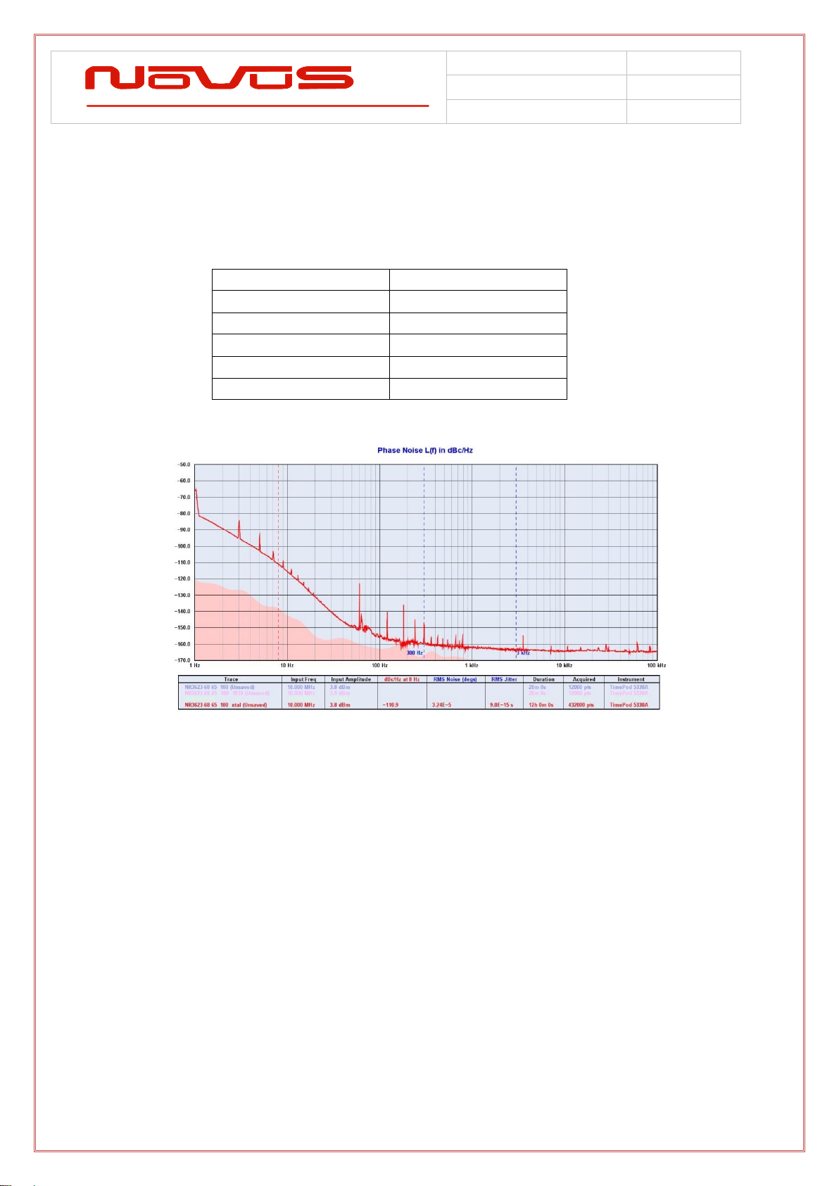
Performance .........................................................................................................................22
Environmental and Mechanical .............................................................................................22
LIMITED HARDWARE WARRANTY ....................................................................................... 23

USERS MANUAL
NR2306-O/G
REVISION
A
DATE
3-8-18
Page | 3
1.0 Overview
The NR2306 is one of our most versatile and featured references. The
instrument starts with an ultra-low phase noise OCXO. The OCXO can be
locked to either the GNSS, an external PPS, external 10 MHz sine or an
external 1300nm fiber optic 10 MHz source.

USERS MANUAL
NR2306-O/G
REVISION
A
DATE
3-8-18
Page | 4
The typical phase noise is indicated below.
10 MHz Sine - Primary Output
Offset Frequency (Hz)
Typical (dBc / Hz)
1
-95
10
-140
100
-152
1000
-160
10000
-165
The disciplined OCXO drives a synthesizer to create a PPS from the OCXO to
dramatically reduce PPS jitter. PPS jitter directly from the GNSS receiver will
be as much as 5 to 10 ns of jitter introduced by the RF link - multi-path and
other effects. The internal control loop modulates the OCXO frequency to
maintain frequency and minimize the timing difference between the GNSS-PPS
and the synthesized PPS. The PPS output drive can be HVCMOS,LVCMOS or
50 Ohm compatible.
For even greater flexibility, the OCXO can be disciplined to an external PPS, 10
MHz RF or a fiber optic source. The fiber optic source is 1300nm single mode
or multi-mode.
The output amplifiers are safe area protected as well as transient and fault
protected. Each output is monitored with an RMS to DC converter. An alert can
be set-up to measure an over-voltage and under-voltage state.

USERS MANUAL
NR2306-O/G
REVISION
A
DATE
3-8-18
Page | 5
A front panel display, and pushbuttons allow the user to monitor and control the
instrument locally.
A RS232 port allows for local control and monitoring and an Ethernet port is
used for remote control and monitoring. The unit supports SNMP V04 for
remote access and control.
For GNSS locked configurations, a dual-time base option is offered. The
second time base effectively controls an embedded frequency counter to
confirm that the primary 10 MHz is within specification.
The unit consumes less than 10 watts of power and can operate from global
AC power: 90 to 240 Vac - 50/60 Hz.
The OCXO is a low phase noise device that is vibration-isolated from the PCB
assembly to attenuate mechanical vibration. In particular, 60 Hz fan vibration is
attenuated by ~ 20 db.

USERS MANUAL
NR2306-O/G
REVISION
A
DATE
3-8-18
Page | 6
Each output is monitored and transient and fault protected. Output amplitude is
measured and available via the RS232 port or optional Internet port. There is
also a status relay that is normally closed that will open if the unit fails self-test.
2.0 Controls and Indicators –Front Panel
This section describes the functionality of the front panel controls and indicators. Two
buttons above the status LEDs provide navigation through the menus.
In general, the NEXT button advances through the menus to the next screen, while the
SELECT button chooses between the available values on a menu.
Menus that allow selectable adjustments are the Input Threshold, Alert Threshold, and the
Attenuation setting. To adjust these values from the front panel, hold down both buttons for
two seconds, until the value begins to flash. To leave the menu with the new value, hold
down both buttons until the value is solid.

USERS MANUAL
NR2306-O/G
REVISION
A
DATE
3-8-18
Page | 7
2.1 GNSS Status
On power-up, the NR2306-O/G will display the Time and Date as well as the current status
of both GNSS receivers (if a dual-time base option was ordered).
GNSS: The GNSS status indication allows the user to observe the Lock status of the
receivers, and the number of GNSS satellites in view. Before GNSS lock is acquired, the
status will be “Tracking” and the number of satellites will be shown. When GNSS lock is
acquired, the status will change to “Lock.”
Time and Date: The time zone will be UTC by default, but the hour can be offset to the
local time in the UTC Offset menu. Changes to UTC offset and Hour mode will be reflected
on this screen, but will not change the NMEA output data.
2.2 GNSS Detailed Status
The GNSS Status Menu gives the user a quick reference for the quality of the GNSS
satellite signal and length of time that each receiver has been locked.
To toggle between each receiver, press the SELECT button. The screen will display which
receiver status is being viewed.
The user can then see the number of GPS satellites in view, number of GLONASS
satellites in view, and the UTC time and date that lock occurred on the selected receiver.
2.3 Channel Status
The Channel Status can be determined by reading the actual RMS value on the output of
each stage. This is compared to a threshold limit that is set by the user as a percentage
variation from a saved value. The default variation value is set at ±55% from the current
state of the amplifier and is user-programmable in 5% increments from ±10% to ±60%.

USERS MANUAL
NR2306-O/G
REVISION
A
DATE
3-8-18
Page | 8
The range of acceptable Channel Amplitude can be narrowed around a connected
balanced line, so that a Channel Status below the Alert Threshold indicates a shorted line,
while a Channel Status above the Alert Threshold window indicates a potential
disconnected cable.
The threshold value at which a channel alert is triggered can be programmed on the Alert
Threshold screen or programmed via the RS232 port. Once set, the unit would continue to
monitor each channel and a deviation beyond the set limits would be reported as a failure
on the front panel and via RS232.
The Channel Status feature can quickly detect a cabling failure. Any change in the load
impedance will change the output voltage with respect to the divider formed by the output
impedance of the amplifier and the load impedance. Failing cables and connectors can be
detected early.
The current threshold limits are displayed in addition to the actual measured value. These
values reflect the percentage threshold defined in the Alert Threshold settings. If the output
value is too low to give a valid reading, the display will read “LOW.”
The status is displayed on the front panel and is accessible over the RS232 serial bus via
DB9. Channel Statuses can be cycled into view or can remain on a single channel. This
feature can be accessed via the NEXT button by advancing to the Channel Status screen.
To cycle through channels in sequence, press the SELECT button.
Status information is also accessible through the SNMP capability.
2.4 Status LEDs
There are three status LEDs which provide a quick indication of valid unit operation.
Alert LED: The Alert LED will illuminate flashing RED to indicate A GNSS failure or a
power supply failure. The Alert LED will not flash RED if any valid input signal is present.
Oven LED (OCXO option only): The Oven LED will illuminate to indicate an oven failure.
Oven LED (on-board GPS): The Oven LED will illuminate steady GREEN if all on-board
GPS/GNSS units are locked. The LED will flash GREEN if at least one unit is unlocked.

USERS MANUAL
NR2306-O/G
REVISION
A
DATE
3-8-18
Page | 9
Fault LED: The Fault LED will illuminate flashing RED to indicate a channel fault, when
any single channel is outside the user-defined threshold.
2.5 Alert Threshold
The Alert Threshold screen allows the user to adjust the tolerance from the Reference
Voltage which, if exceeded in either direction, the output channels will report a fault status.
The default threshold value is set at ±55% percent from the current state of the amplifier,
and is user-programmable in 5% increments, from ±10% to ±60%.
Each channel has a Reference Voltage which can be set, all at once, by latching the
channels current value in the Latch Channel Average Screen. Each channels reference
voltage can be set individually by writing the value serially with the $SET command. After
saving the current configuration on a channel, any subsequent deviation on that channel
which exceeds the Alert Threshold percentage will trigger an alert.
Steps to ensure correct Alert configuration:
1. Connect distribution cabling to channels 1 through 6.
2. Set Alert Threshold to desired range.
3. Save current channel voltages with the Latch Channel Values Screen.
4. Save current settings on the Save Configuration screen.

USERS MANUAL
NR2306-O/G
REVISION
A
DATE
3-8-18
Page | 10
The Alert Threshold can be optimized so that a channel short or an impedance change will
cause an Alert.
Example:
The output of Channel 1 is connected to a high impedance input and reports 1.25Vrms at
the output. The output of Channel 2 is connected to a 50Ohm terminated input, and reports
0.90Vrms at the output.
Alert threshold is set to +/-20%.
The current state is saved in the Save Configuration screen.
The Channel 1 alert will report when:
-The Channel 1 output is higher than 1.50Vrms
-The Channel 1 output is lower than 1.00Vrms

USERS MANUAL
NR2306-O/G
REVISION
A
DATE
3-8-18
Page | 11
The Channel 2 Alert will report when:
-The Channel 2 output is higher than 1.08Vrms
-The Channel 2 output is lower than 0.72Vrms
To adjust the Alert Threshold from the front panel, hold the NEXT and SELECT buttons
down simultaneously for two seconds. The percentage value will begin flashing. To
increase the value, press the SELECT button. To decrease the value, press the NEXT
button.
When the desired value is reached, press the NEXT and SELECT button simultaneously to
leave the settings mode.
The Alert Threshold settings can be modified via the RS232 serial port with the $FLTTHR
command.
For details on the Alert Threshold, see Programmer’s Guide.
2.6 Latch Channel Values
The Latch Channel Values Screen allows the user to save the current channel output
values for use as the Reference Value for Alert settings.
A channel Alert is triggered when a channel output voltage exceeds or falls below a
percentage of the reference value. This reference value is 1.10Vrms as a default, but can
be set by the user.
There are two ways to set the reference voltage. The RS232 serial port allows for setting
an individual channels reference voltage with the $SET command. The user can also use
the Latch Channel Values to take a snapshot of all current outputs and use these as the
reference values.
2.7 PPS Status
The PPS (one Pulse Per Second) relationship with the NMEA data is shown
below:

USERS MANUAL
NR2306-O/G
REVISION
A
DATE
3-8-18
Page | 12
The serial data timing is for the next rising edge of the PPS pulse.
The PPS from the active GPS is monitored to verify output is active. The PPS output can
be disabled or enabled, as well as set to AUTO, which disables the PPS during a user-
defined warm-up period and after a user-defined holdover period has been exceeded.
The $PWH (PPS Warmup/Holdover) setting can be changed via the serial port to one of the
three available settings:
$PWH=0
Off: PPS is disabled regardless of Warmup/Holdover status.
$PWH=1
Auto: Disabled during Warmup, disabled after holdover is
exceeded.
(Enabled after warmup, during valid holdover)
$PWH=2
On: PPS is enabled regardless of Warmup/Holdover status.
Each GPS/GNSS may be addressed separately, and the settings can be viewed on the
PPS Enable/Disable screen.
The GPS settings will be displayed for each GPS receiver, whether AUTO PPS, ENABLD
PPS, or DISABLD PPS. If the option of a second GPS was not ordered, N/A will be
indicated.
The PPS measurement will indicate ACTIVE PPS if the output measures a PPS present. If
the PPS is not present due to the warmup period not having been completed, while in
AUTO PPS mode, the screen will indicate WARMUP WAIT.

USERS MANUAL
NR2306-O/G
REVISION
A
DATE
3-8-18
Page | 13
If the GPS has remained unlocked for a period which exceeds the user-defined holdover
period, the PPS status will indicate HLDOVR ERR.
Status of the Warmup and Holdover counters can also be monitored from the $GPNVS
string 11, which includes Warmup Complete and Holdover Valid fields, as well as frequency
valid fields.
The PPS drive can be LVCMOS, HVCMOS or 50 Ohm load compatible. The output
configuration required is factory set.
If a dual GPS/GNSS option is installed, the currently selected GPS PPS will be noted with
an arrow. This arrow indicates the actual source of the PPS. In addition, the Active GPS
will be noted with an arrow as well. The arrow will indicate switching to back-up in the case
of failure of the primary, or loss of lock, as set in GPS Select setting.
2.8 GPS Select (Dual Time Base Feature)
The GPS Select screen is present on the NR2306 with the dual GPS/GNSS receivers
option. This screen allows the user to specify which GPS source is the primary output
source for the PPS and 10MHz outputs.

USERS MANUAL
NR2306-O/G
REVISION
A
DATE
3-8-18
Page | 14
There are four settings, and these are the same as the serial command $GPS:
Setting
Description
Serial
Command
GPS 1
GPS 1 is used as output regardless of lock status or error
$GPS=0
GPS 2
GPS 2 is used as output regardless of lock status or error
$GPS=1
AUTO (1)
GPS 1 is default, if locked and no errors, else GPS 2 is used
$GPS=2
AUTO (2)
GPS 2 is default, if locked and no errors, else GPS 1 is used
$GPS=3
To cycle through the selections, use the SELECT button. To save, go to the Save
Configuration Screen, or use the serial $SAVEFLASH command. The default setting is
Auto (1).
The GPS Select setting also determines the output of the GPS/GNSS specific strings to the
serial RS232 and the SNMP GPS specific settings. The strings that follow the specified
GPS are the RMC, GNS, GSA, GSV, ZDA, and NVS (strings 7 through 11).
2.9 Save Configuration
The Save Configuration screen allows the user to save the current settings for Alert
Threshold, Input Threshold, Attenuation, Input Select, Reference Voltage and any other
settings that have been modified via the RS232 port.
To save the current settings, press the SELECT button twice.
The Save Configuration action is equivalent to the $SAVEFL command on the serial port.
2.10 Fault Status
The Fault Status screen allows a quick overview of any Channel faults from the front panel.
The total fault count is listed, as well as a visual flashing indication of any channels that are
beyond the threshold values.

USERS MANUAL
NR2306-O/G
REVISION
A
DATE
3-8-18
Page | 15
Press SELECT to advance to the System Fault screen.
The System Fault screen indicates any failures in the primary system or the redundant
back-up system. All internal power supplies are monitored (24V, +8V, -8V, 5V) on both the
primary and back-up systems. A failure on one of these supplies will be indicated with a “PS
FAIL” fail warning for either system. A communication failure would be indicated by a “Com
FAIL” indicator. Either of these fault statuses will result in the change of the primary to the
backup system. The individual statuses of the internal power supplies are also available via
the RS232 serial port.
The presence of a valid DC input voltage is indicated on this screen, as well as a valid AC
power input. If either of these supplies are not present, a “FL” indication will be shown next
to the appropriate input.
2.11 UTC Mode
The user can select how the time is displayed on the screen by choosing between three
formats: UTC, 24 hour mode, or 12 hour mode. Toggle through the modes by pressing the
SELECT button.
If 24 hour mode or 12 hour mode is chosen, the GMT offset will be applied to the displayed
time. If GMT mode is selected, no offset will be applied to the displayed time.
2.12 GMT Offset
With 24 hour mode or 12 hour mode, the user can choose to align the displayed hour with
their current time zone. Using the SELECT button, toggle to the desired offset. The offset
will decrement through the 24 hour period, from UTC-11 to UTC +12, etc.

USERS MANUAL
NR2306-O/G
REVISION
A
DATE
3-8-18
Page | 16
Adjusting the GMT offset will affect the displayed date. As the hour moves across the
International Dateline, the displayed date will reflect the date in the selected time zone, and
not necessarily the GMT date.
2.13 Power Switch
The front or rear panel Power Switch controls AC Power input to the unit. If the optional
DC input is provided with 24V, or a valid DC supply, the unit will operate. In other words,
the front panel switch will not remove power if the optional DC input is powered.
The AC and DC input option provides a redundant and automatic back-up source in the
case of failure of either input.
3.0 Rear Panel
3.1 Channel Outputs –SMA
There are six 10 MHz outputs across the left-hand side of the rear panel. They are labeled
1 through 6. Nominally, the outputs are 50 Ohm impedance. The PPS is available on the
seventh connector.
3.2 Antenna Input A/B –SMA
SMA female –Internal 3.5V supply, 45mA max. In the case of a dual-time-base
configuration, the unit can accept two separate antenna or a single antenna can be used
with an internal splitter. The single antenna configuration gives up 6 dB of sensitivity for a
simpler configuration. The system margin is approximately 30 dB. Therefore, in most
installations the single antenna will work acceptably.

USERS MANUAL
NR2306-O/G
REVISION
A
DATE
3-8-18
Page | 17
3.3 DC Input
The DC input connector is a 3 pin Amphenol circular connector, P/N DL3102A10SL-3P.
The mating connector is available as P/N DL3106A10SL-3S.
The default DC input voltage is 24Vdc. Custom voltage ranges can be provided from -
60Vdc to +60Vdc.
Pin A goes to the most negative voltage of the DC source. For a 24V source input, this
would be the ground or return output from the DC source.
Pin B goes to the most positive DC voltage of the DC source. For a 24V source input, this
would be the positive output from the DC source.
Pin C goes to the Earth ground of the DC source.
3.4 AC Input
The AC input accepts 90-250Vac, 50-60Hz. IEC 320-C14 compliant.
4.0 GNSS Receiver
The 26 channel GNSS receiver and companion elements generate the GNSS PPS
and NMEA serial link. The serial link conforms to NMEA 0183 protocol.
GPS, GLONASS, QZSS, SBAS, Active Anti-Jamming and Advanced Multipath
Mitigation Functions.
Supports concurrent GPS, GLONASS, SBAS and QZSS. Galileo Ready.
Sensitivity:
GPS
Tracking: -161 dBm
Hot Start: -161 dBm
Warm Start: -147 dBm
Cold Start: -147 dBm
Reacquisition: -161 dBm
GLONASS
Tracking: -157 dBm
Hot Start: -157 dBm
Warm Start: -143 dBm
Cold Start: -143 dBm
Reacquisition: -157 dBm

USERS MANUAL
NR2306-O/G
REVISION
A
DATE
3-8-18
Page | 18
TTFF (Time to First Fix)
Hot Start: <5 sec (@-130 dBm)
Warm Start: 35 sec (@-130 dBm)
Cold Start: 40 sec (@-130 dBm)
・Active Anti-Jamming
・Advanced Multipath Mitigation
The receiver needs at least four satellite vehicles (SVs) visible to obtain an
accurate 3-D position fix. When travelling in a valley, or built-up area, or under
heavy tree cover, you will have trouble acquiring and maintaining a coherent
satellite lock. Complete satellite lock may be lost, or only enough satellites (3)
tracked to be able to compute a 2-D position fix, or a poor 3D fix due to
insufficient satellite geometry (i.e. poor DOP). It may not be possible to update a
position fix inside a building or beneath a bridge. The receiver can operate in 2-D
mode if it goes down to seeing only three satellites by assuming its height
remains constant. But this assumption can lead to very large errors, especially
when a change in height does occur. A 2-D position fix is not considered a good
or accurate fix; it is simply “better than nothing”.
The receiver’s antenna must have a clear view of the sky to acquire satellite lock.
Remember, it is the location of the antenna that will be given as the position fix. If
the antenna is mounted on a vehicle, survey pole, or backpack, allowance for
this must be made when using the solution. The GNSS receiver provides power
for the LNA in the antenna. The unit was designed to provide 3.5 Vdc < 40 mA of
current.
To measure the range from the satellite to the receiver, two criteria are required:
signal transmission time and signal reception time. All GPS satellites have
several atomic clocks that keep precise time and are used to time-tag the
message (i.e. code the transmission time onto the signal) and to control the
transmission sequence of the coded signal. The receiver has an internal clock to
precisely identify the arrival time of the signal. Transit speed of the signal is a
known constant (the speed of light), therefore: time x speed of light = distance.

USERS MANUAL
NR2306-O/G
REVISION
A
DATE
3-8-18
Page | 19
Once the receiver calculates the range to a satellite, it knows that it lies
somewhere on an imaginary sphere whose radius is equal to this range. If a
second satellite is then found, a second sphere can again be calculated from this
range information. The receiver will now know that it lies somewhere on the
circle of points produced where these two spheres intersect.
When a third satellite is detected, and a range determined, a third sphere
intersects the area formed by the other two. This intersection occurs at just two
points. A fourth satellite is then used to synchronize the receiver clock to the
satellite clocks.
In practice, just four satellite measurements are sufficient for the receiver to
determine a position, as one of the two points will be totally unreasonable
(possibly many kilometers out into space). This assumes the satellite and
receiver timing to be identical. In reality, when the receiver compares the
incoming signal with its own internal copy of the code and clock, the two will no
longer be synchronized. Timing error in the satellite clocks, the receiver, and
other anomalies mean that the measurement of the signal transit time is in error.
This, effectively, is a constant for all satellites since each measurement is made
simultaneously on parallel tracking channels. Because of this, the resulting
ranges calculated are known as “pseudo-ranges”.
5.0 Antenna
Antenna –SMA
SMA female antenna connection provides internal 3.5VDC power at <40mA
max. The Novus NA103 pole mount antennas or the Novus NA106 magnetic
mount antenna are recommended for optimal performance.
The receiver and companion elements generate the PPS and NMEA serial link.
The serial link conforms to NMEA 0183 protocol. The 26 channel high-sensitivity,
high-accuracy Multi-GNSS receiver supports TRAIM, GPS, GLONASS, QZSS,
SBAS, Active Anti-Jamming and Advanced Multipath Mitigation Functions.

USERS MANUAL
NR2306-O/G
REVISION
A
DATE
3-8-18
Page | 20
Typical Antenna Specs:
Frequency Band 1574 –1607 MHz
Antenna Gain 2 dBic @ 90°
Amplifier Gain @ 3.0Vdc: 26dB (typ)
Polarization RHCP
Out-of-band Rejection >60dBc @ f0 ± 50MHz
Impedance 50Ω
VSWR 2.0 Max
DC Input 2.8V - 6V
Noise Figure <2.0dB
Power Consumption 25mA (typ)
6.0 Programming Guide (RS232 Port)
The NR2306-O/G can accept user commands which will provide specific status
and performance feedback and which may be customized by the user. Many of
the settings can be saved in non-volatile flash memory.
If the user makes changes which are intended to be kept between power-off
cycles, the command “$SAVEFLASH*51 <CR><LF>” will update flash to reflect
all current settings.
Table 1 shows a complete list of input commands and descriptions that are
handled by the internal processor. In general, a command may be input without
“=” or an additional value, and the unit will respond with the current settings
value. If the input is not understood, the microcontroller will return the value
“$?*3F<CR><LF>”
NOTE: All commands should be prefixed with “$” and followed by <cr><lf>.
Checksum can be enabled which requires the command to be followed by
an asterisk (*) and a two digit hex value.
Example: $<COMMAND>*XX<cr><lf>.
The checksum can be required for all input commands and the requirement for a
checksum can be enabled or disabled (default setting is disabled). The
checksum method is the two-hexadecimal character representation of an XOR of
all characters in the sentence between, but not including, the $ and the *
character.
Example: $NVS1=1*76
Table of contents
Popular Industrial Electrical manuals by other brands

Murata
Murata GRM155R60J103KA01 Series Reference sheet

Eltroplan
Eltroplan REVCON RHD Series operating instructions

Murata
Murata GRM155C80J564KE15 Series Reference sheet

M-system
M-system 18KYCH instruction manual

Murata
Murata GJM0335C1E220GB01 Series Reference sheet

Colorado Data Systems
Colorado Data Systems 53A-570 operating manual

IFM
IFM DP2402 operating instructions

Murata
Murata GQM22M5C2H200GB01 Series Reference sheet

Thermo Scientific
Thermo Scientific 9101BN user guide

TuControls
TuControls Safepod installation instructions

Murata
Murata GRM188R71E104MA01 Series Reference sheet

Murata
Murata GQM1555C2D3R7BB01 Series Reference sheet