IFM DP2402 User manual

Operating instructions
Pulse stretcher
DP2402
11420212 / 0001 / 2022
GB

DP2402 Pulse stretcher
2
Contents
1 Preliminary note ............................................................. 4
1.1 Symbols used.......................................................... 4
1.2 Warnings used ......................................................... 4
1.3 Safety symbol on the device............................................... 4
2 Safety instructions............................................................ 5
3 Intended use................................................................ 6
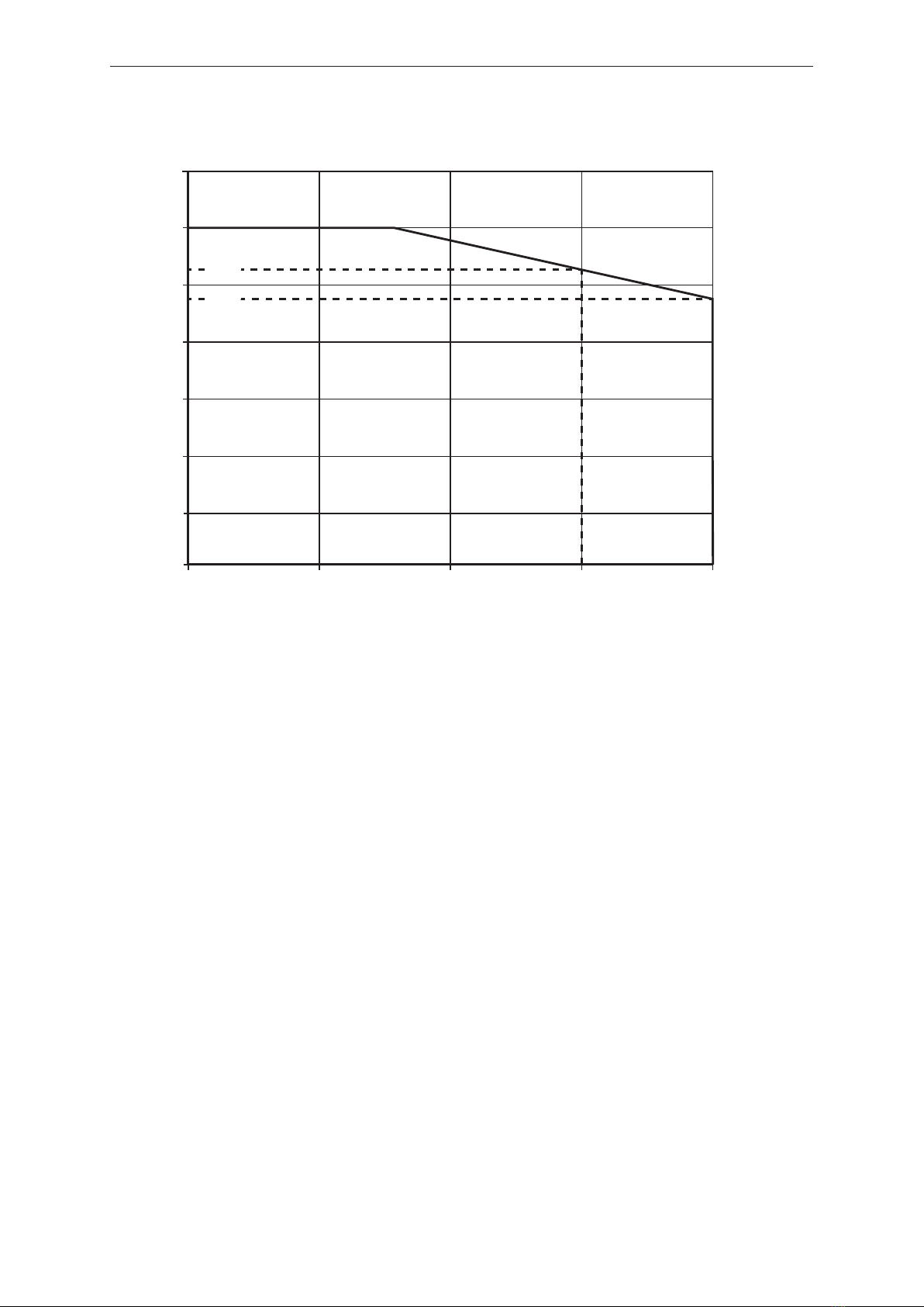
3.1 Temperature derating depending on the altitude . . . . . . . . . . . . . . . . . . . . . . . . . . . . . . . . 7
4 Function ................................................................... 8
4.1 Application as an IO-Link device............................................ 8
4.1.1 General information.................................................. 8
4.1.2 Application ........................................................ 8
4.1.3 IO Device Description (IODD).......................................... 8
4.2 Function diagrams....................................................... 8
4.2.1 Input configuration: pulse-controlled . . . . . . . . . . . . . . . . . . . . . . . . . . . . . . . . . . . . . 8
4.2.2 Input configuration: edge-controlled . . . . . . . . . . . . . . . . . . . . . . . . . . . . . . . . . . . . . 9
5 Installation.................................................................. 10
6 Electrical connection.......................................................... 11
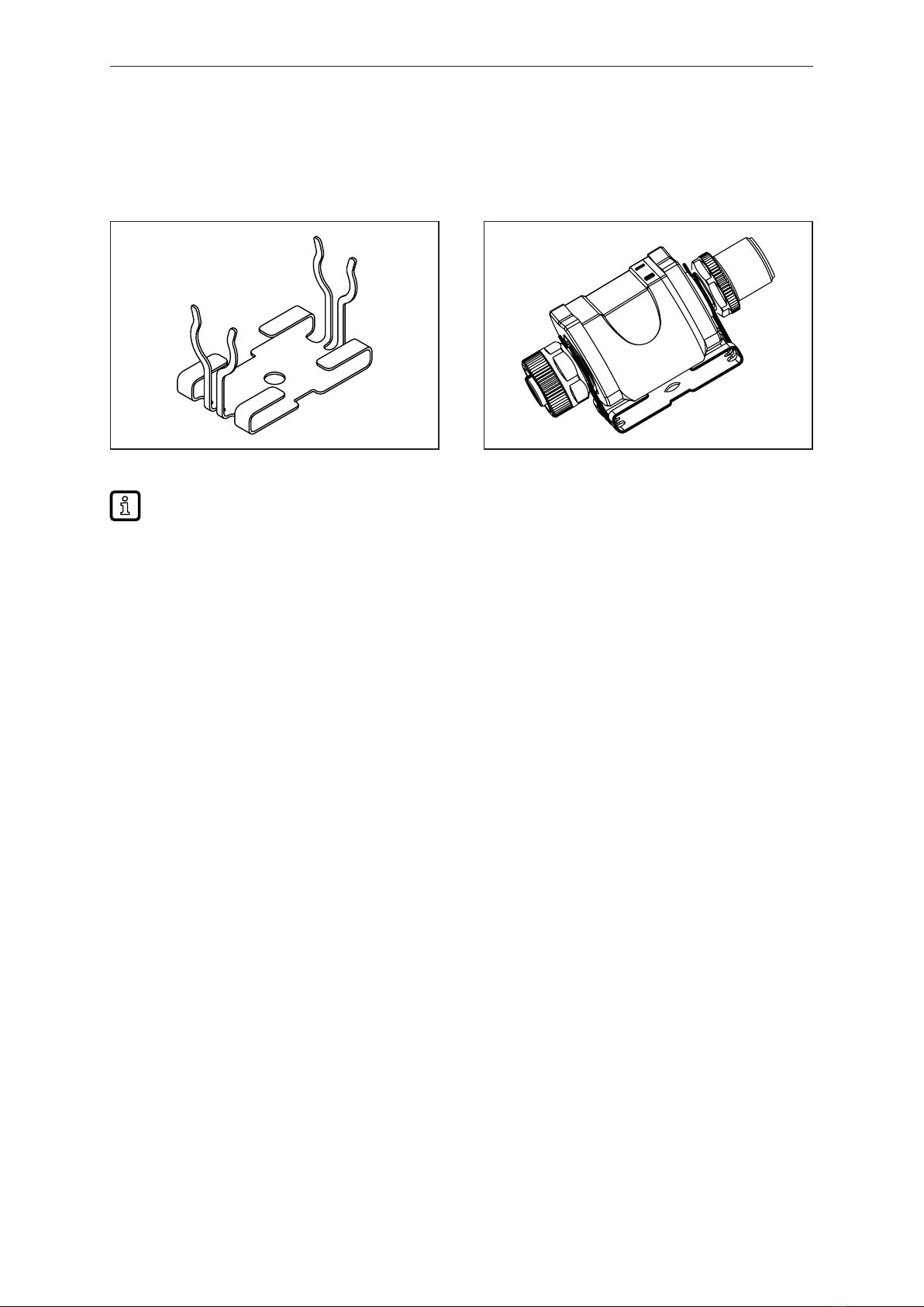
6.1 Mounting the connector................................................... 12
6.2 Removing the connector.................................................. 12
6.3 Cable length........................................................... 12
7 Operating and display elements................................................. 13
7.1 Push rings (pushbuttons) ................................................. 13
7.2 LEDs................................................................. 13
7.3 Indication ............................................................. 14
8 Menu...................................................................... 15
8.1 General............................................................... 15
8.2 Menu structure ......................................................... 15
8.3 Parameters of the main menu.............................................. 15
8.3.1 OUt1 ─ output OUT1................................................. 15
8.3.2 OUt2 ─ output OUT2................................................. 16
8.3.3 EF ─ extended functions.............................................. 16
8.4 Parameters for OUT1.................................................... 16
8.4.1 ou1 ─ output configuration ............................................ 16
8.4.2 dIn1 ─ input configuration............................................. 16
8.4.3 dS1 ─ switch-on delay ............................................... 16
8.4.4 dr1 ─ switch-off delay................................................ 16
8.4.5 h.t1 ─ hold time..................................................... 16
8.5 Parameters for OUT2.................................................... 16
8.5.1 ou2 ─ output configuration ............................................ 16
8.5.2 dIn2 ─ input configuration............................................. 17
8.5.3 dS2 ─ switch-on delay ............................................... 17
8.5.4 dr2 ─ switch-off delay................................................ 17
8.5.5 h.t2 ─ hold time..................................................... 17
8.6 Parameters of the extended functions (EF) . . . . . . . . . . . . . . . . . . . . . . . . . . . . . . . . . . . . 17
8.6.1 rES ─ restore factory setting........................................... 17
8.7 Parameters adjustable via IO-Link .......................................... 17
8.7.1 FLASH_ON – activate flashing of the display . . . . . . . . . . . . . . . . . . . . . . . . . . . . . . 17
8.7.2 FLASH_OFF – deactivate flashing of the display . . . . . . . . . . . . . . . . . . . . . . . . . . . 18
8.7.3 internal_temperature – operating temperature microcontroller . . . . . . . . . . . . . . . . . 18
8.7.4 operation_hours – operating hours . . . . . . . . . . . . . . . . . . . . . . . . . . . . . . . . . . . . . . 18
8.7.5 Application-specific tag............................................... 18
8.7.6 Location tag ....................................................... 18
8.7.7 Function tag ....................................................... 18
9 Parameter setting............................................................ 19
9.1 Parameter setting in general............................................... 19
9.1.1 Example [ou2] - output configuration for OUT2 . . . . . . . . . . . . . . . . . . . . . . . . . . . . . 19

Pulse stretcher DP2402
3
9.2 Notes on programming................................................... 20
9.2.1 Locking / unlocking.................................................. 20
9.2.2 Timeout........................................................... 20
9.2.3 Numerical entries with [▼] or [▲] . . . . . . . . . . . . . . . . . . . . . . . . . . . . . . . . . . . . . . . 20
10 Operation .................................................................. 21
11 Troubleshooting ............................................................. 22
12 Maintenance, repair and disposal................................................ 23
13 Factory settings.............................................................. 24

DP2402 Pulse stretcher
4
1 Preliminary note
You will find instructions, technical data, approvals and further information using the QR code on the
unit / packaging or at www.ifm.com.
1.1 Symbols used
Requirement
Instructions
Reaction, result
[...] Designation of keys, buttons or indications
Cross-reference
Important note
Non-compliance may result in malfunction or interference.
Information
Supplementary note
1.2 Warnings used
CAUTION
Warning of personal injury
wSlight reversible injuries may result.
1.3 Safety symbol on the device
Safety symbol on the device:
uAdhere to the operating instructions for the safe operation of the unit.

Pulse stretcher DP2402
5
2 Safety instructions
• The unit described is a subcomponent for integration into a system.
– The system architect is responsible for the safety of the system.
– The system architect undertakes to perform a risk assessment and to create documentation in
accordance with legal and normative requirements to be provided to the operator and user of
the system. This documentation must contain all necessary information and safety instructions
for the operator, the user and, if applicable, for any service personnel authorised by the
architect of the system.
• Read this document before setting up the product and keep it during the entire service life.
• The product must be suitable for the corresponding applications and environmental conditions
without any restrictions.
• Only use the product for its intended purpose (Ò Intended use).
• If the operating instructions or the technical data are not adhered to, personal injury and/or damage
to property may occur.
• The manufacturer assumes no liability or warranty for any consequences caused by tampering with
the product or incorrect use by the operator.
• Installation, electrical connection, set-up, programming, configuration, operation and maintenance
of the product must be carried out by personnel qualified and authorised for the respective activity.
• Protect units and cables against damage.
• Replace damaged units, otherwise the technical data and safety will be impaired.
• Observe applicable documents.

DP2402 Pulse stretcher
6
3 Intended use
The device can output incoming pulses stretched at the output. The device is designed as a standard
IO device. IO-Link only serves as a configuration interface.
2
3
4
5
1
ti
t
1
0
1
0
Fig.1: Example: Pulse stretching between sensor and evaluation unit
1: Conveyor belt 2: Pulse generator on the conveyor belt
3: DP2402 4: Transistor output
5: PLC, evaluation units, ...
The unit is not suited for environments with particular requirements on mechanical stability (e.g.
shock/vibration).
The unit is intended for indoor use only.
uObserve the operating conditions (Ò Technical data at www.ifm.com).
The accuracy and functionality of the unit can only be guaranteed within the specification.
If necessary, the user must provide appropriate digital input filters for the input signals.

Pulse stretcher DP2402
7
3.1 Temperature derating depending on the altitude
0 1000 2000 3000 4000
h [m]
60
50
40
30
20
10
TA[°C]
52
48

DP2402 Pulse stretcher
8
4 Function
The device supports two different output behaviours:
1. It can output an input pulse stretched, shortened or delayed at the output.
2. The edge of the input signal can serve as a trigger to initiate a pulse at the output. The pulse
duration is set via a parameter.
For parameter setting and diagnostic purposes there is an IO-Link interface available. The following
options are available:
• Remote parameter setting: reading and changing the current parameter setting
• IO-Link parameter setting: IO Device Description (IODD) (Ò/8)
For diagnostic purposes, the input states and output states are available via the process data.
Due to the cycle time, the correctness of the process date displayed via IO-Link cannot be
guaranteed.
4.1 Application as an IO-Link device
4.1.1 General information
The unit has an IO-Link communication interface which requires an IO-Link capable module (IO-Link
master).
The IO-Link interface allows direct access to the process and diagnostic data and enables setting of
the parameters of the unit during operation.
You will find further information about IO-Link and all the necessary information about the required IO-
Link hardware and software at:
www.ifm.com/gb/io-link
4.1.2 Application
The use of the IO-Link interface in the application is not intended. It is mainly used for convenient
setting of the device.
4.1.3 IO Device Description (IODD)
You will find the IODDs necessary for the configuration of the IO-Link device and detailed information
about process data structure, diagnostic information and parameter addresses at:
www.ifm.com
4.2 Function diagrams
The output is defined as a normally open (no) or normally closed (nc) via the parameter [ou1] or [ou2].
4.2.1 Input configuration: pulse-controlled
The application of the switch-on and switch-off delay makes it possible to output input pulses
stretched, shortened or delayed at the output. The duration of the output pulse depends on the pulse
duration at the input.

Pulse stretcher DP2402
9
t
t
t
dS dS
dS
Input signal
Output signal (no)
Output signal (nc)
Fig.2: Switch-on delay
t
t
t
dr dr
dr
Input signal
Output signal (no)
Output signal (nc)
Fig.3: Switch-off delay
After switching on, the device will not function properly until there is at least one rising edge at
the input.
4.2.2 Input configuration: edge-controlled
The edge of the input signal is the trigger for the output of pulses at the output. The duration of the
output pulse is always constant and is determined by the parameter [h.t1] or [h.t2]. The trigger can be
set to either the positive or negative edge.
t
t
t
h.t h.t h.t
h.t
Input signal
Output signal (no)
Output signal (nc)
Fig.4: Hold time

DP2402 Pulse stretcher
10
5 Installation
uInstall the unit so that the M12 connection parts and the unit are protected from mechanical stress
such as shock and vibration.
uIf necessary, fix the unit with a clamp (use M4 screw or cable tie).
Fig.5: Mounting clip Fig.6: Mounting clip with attached unit
The mounting clip is not supplied with the unit. More information about available accessories at
www.ifm.com.

Pulse stretcher DP2402
11
6 Electrical connection
The unit must be connected by a qualified electrician.
Observe the national and international regulations for the installation of electrical equipment.
Voltage supply according to SELV, PELV.
By means of basic insulation according to EN61010-1, the circuits are isolated from each other and
from device surfaces that could be touched (secondary circuit with max. 30 V DC, supplied from mains
circuit up to 300 V overvoltage category II).
CAUTION
Input current is not limited.
wNo fire protection.
uProtect circuits.
uProtect circuits.
Potential M12 connector ①Fuse
L+ / supply voltage Pin 1 ≤ 2 A
Required tripping characteristic of the fuses:
Tfuse ≤ 120 s at max. 6.25 A (fire protection)
uAlternatively supply the unit via a limited energy circuit according to IEC61010-1 or class 2
according to UL1310.
Output reaction to overload or short circuit:
For self-protection of the output in case of excessive thermal load (due to short circuit or
overload), the output driver starts clocking. If a short circuit / overload continues for several
hours, the driver may be damaged!
uDisconnect power.
uConnect the unit as follows:
2
1
43
2 1
3
1 2
4
5
Fig.7: Electrical connection
1: 4-pole M12 connector
(output side)
• Pin 1: L+ / supply voltage
• Pin 2: OUT2 / digital output 2
• Pin 3: L- / supply voltage
• Pin 4: OUT1 / digital output 1/ IO-Link (C/Q)
2: 5-pole M12 socket
(input side)
• Pin 1: L+
• Pin 2: IN2 / digital input 2
• Pin 3: L-
• Pin 4: IN1 / digital input 1
• Pin 5: not used
The unit must not be externally supplied via the 5-pole M12 input socket ② .
Always use the provided connection cables to connect other devices.
See also application examples (Ò Intended use)

DP2402 Pulse stretcher
12
6.1 Mounting the connector
To achieve the protection rating indicated in the data sheet, the following has to be observed:
uUse IO-Link cable with IP class.
uUse M12 connectors with gold-plated contacts.
uConnect the connector with the unit. The arrow indicates the position of the coding.
uCarry out the fitting according to the indications of the cable manufacturer.
• Maximum tightening torque on the connector side ➀: 1.8 Nm
• Maximum tightening torque o the socket side ➁: 1.3 ±0.1 Nm
6.2 Removing the connector
uPress the connector against the unit and simultaneously loosen the coupling nut.
6.3 Cable length
• Without IO-Link communication: 30 m on each side
• With IO-Link communication: 20 m on the master side
uProvide all input and output side cables with a strain relief approx. 200 mm behind the connectors.

Pulse stretcher DP2402
13
7 Operating and display elements
2
3
1
1: Push rings (pushbuttons)
2: LEDs
3: Display
Here, the Enter button [●] is shown pressed, as an exam-
ple.
7.1 Push rings (pushbuttons)
To execute an [esc], [●], [▼] or [▲] command, press the corresponding corner of a push ring.
Button Function
[esc] Escape Return to the previous menu. Exit parameter setting without saving the new value.
[●] Enter Open menu mode.
Selection of the parameter and acknowledgement of a parameter value.
[▼] Down Selection of a parameter. Setting a parameter value (scrolling by holding down, incremen-
tally by pressing repeatedly).
[▲] Up
To ensure correct operation of the push rings (buttons), do not install or place the unit directly
on a metal surface.
For the installation use the mounting clip Ò Installation.
7.2 LEDs
LED Colour Status Designation
I OUT1 yellow on Output 1 switched.
Power green on Voltage supply OK.
Device in operating mode.
off No voltage supply.
Device switched off.
II OUT2 yellow on Output 2 switched.
Error signals and diagnostics: Troubleshooting

DP2402 Pulse stretcher
14
7.3 Indication
Colour Designation
Red 7-segment LED display, 4 digits
Error signals and diagnostics: Troubleshooting
In operating mode, no value is shown on the display.

Pulse stretcher DP2402
15
8 Menu
8.1 General
Irrespective of the operating mode (standard IO mode or IO-Link device) there are two options to set
the parameters of the unit:
• directly on the unit via the menu Parameter setting (Ò/19)
• or via an IO-Link tool
Access via an IO-Link tool has a higher priority than parameter setting via the menu.
Parameter cloning and parameter setting backup is possible with an IO-Link tool.
Some parameters can only be set via the IO-Link interface:
Parameters adjustable via IO-Link.
If the unit was locked via IO-Link, it can also only be unlocked via the IO-Link interface:
Locking / unlocking (Ò/20).
8.2 Menu structure
---
---
ou1 OFF no nc
-Edg
dln1 PULS Edg
OUt1
dS1 0...9999
dr1 0...9999
h.t1 1...9999
ou2 OFF no nc
-Edg
dln2 PULS Edg
OUt2
dS2 0...9999
dr2 0...9999
h.t2 1...9999
12
EF rES ---
Fig.8: Parameters
1: Operating mode: Menu (Ò/15)
2: Parameters of the main menu: Parameters for OUT1 (Ò/16), Parameters for OUT2 (Ò/16) and Parameters of the
extended functions (EF) (Ò/17)
Parameter list and factory settings: Factory settings (Ò/24)
8.3 Parameters of the main menu
8.3.1 OUt1 ─ output OUT1
The parameter opens the menu of the settings for OUT1.

DP2402 Pulse stretcher
16
8.3.2 OUt2 ─ output OUT2
The parameter opens the menu of the settings for OUT2.
8.3.3 EF ─ extended functions
The parameter opens the extended functions menu.
8.4 Parameters for OUT1
8.4.1 ou1 ─ output configuration
Definition of the output logic at output OUT1.
[OFF] = output is switched off.
[no] = switch is closed when activated.
[nc] = switch is opened when activated.
8.4.2 dIn1 ─ input configuration
Configuration of the evaluation of signals at input IN1.
[PULS] = stretched, shortened and delayed output of an input pulse at the output
[EdG] = output of a pulse with defined duration for a rising edge at the input
[-EdG] = output of a pulse with defined duration for a falling edge at the input
8.4.3 dS1 ─ switch-on delay
Delay when the output OUT1 changes to the active switching status.
This function is only available if [PULS] is selected as input configuration.
8.4.4 dr1 ─ switch-off delay
Delay when the output OUT1 changes to the idle state.
This function is only available if [PULS] is selected as input configuration.
8.4.5 h.t1 ─ hold time
Definition of the hold time of output OUT1 in the active switching status.
This function is only available if [EdG] or [-EdG] is selected as input configuration.
8.5 Parameters for OUT2
8.5.1 ou2 ─ output configuration
Definition of the output logic at output OUT2.
[OFF] = output is switched off.

Pulse stretcher DP2402
17
[no] = switch is closed when activated.
[nc] = switch is opened when activated.
8.5.2 dIn2 ─ input configuration
Configuration of the evaluation of signals at input IN2.
[PULS] = stretched, shortened and delayed output of an input pulse at the output
[EdG] = output of a pulse with defined duration for a rising edge at the input
[-EdG] = output of a pulse with defined duration for a falling edge at the input
8.5.3 dS2 ─ switch-on delay
Delay when the output OUT2 changes to the active switching status.
This function is only available if [PULS] is selected as input configuration.
8.5.4 dr2 ─ switch-off delay
Delay when the output OUT2 changes to the idle state.
This function is only available if [PULS] is selected as input configuration.
8.5.5 h.t2 ─ hold time
Definition of the hold time of output OUT2 in the active switching status.
This function is only available if [EdG] or [-EdG] is selected as input configuration.
8.6 Parameters of the extended functions (EF)
8.6.1 rES ─ restore factory setting
Resets all parameters to the Factory settings.
uSelect [rES].
uPress [●].
uPress and hold [▲] or [▼] until [----] is displayed.
uBriefly press [●].
8.7 Parameters adjustable via IO-Link
The following functions or parameters are only available via IO-Link tools.
8.7.1 FLASH_ON – activate flashing of the display
Used to identify a unit. Display flashes and shows [dEVC].

DP2402 Pulse stretcher
18
8.7.2 FLASH_OFF – deactivate flashing of the display
Deactivates the flashing of the display.
8.7.3 internal_temperature – operating temperature microcontroller
Reads the data from the internal temperature sensor of the microcontroller.
8.7.4 operation_hours – operating hours
Only counts full operating hours. Operating times of less than one full hour are not saved. Counter
readings are saved permanently.
8.7.5 Application-specific tag
Customer-specific application description, max. 32 characters long.
Default value: “ *** ” / can be freely defined by the customer
8.7.6 Location tag
Customer-specific location tag of the unit, max. 32 characters long.
Default value: “ *** ” / can be freely defined by the customer
8.7.7 Function tag
Customer-specific function tag of the unit, max. 32 characters long.
Default value: “ *** ” / can be freely defined by the customer

Pulse stretcher DP2402
19
9 Parameter setting
During parameter setting the unit remains in the operating mode. It continues its monitoring
functions with the existing parameters until the parameter setting has been completed.
9.1 Parameter setting in general
Each parameter setting consists of 6 steps:
Step Button
1 Change from operating mode to parameter setting mode. [●]
2 Select the required parameter: [ou1], [dS1], … [▲] or [▼]
3 Change to the programming mode of the parameter. [●]
4 Select or change the parameter value. [▲] or [▼] > 2 s
5 Acknowledge the set parameter value. [●]
6 Return to the operating mode. [esc]
9.1.1 Example [ou2] - output configuration for OUT2
Step Indication
1 Change from operating mode to parameter setting mode.
uPress [●] to get to the menu.
wThe first parameter is displayed.
2 Select the requested parameter, here [OUt2].
uPress [▼] until [OUt2] is displayed.
uPress [●] to get to the extended functions menu.
wThe first parameter of the extended functions is displayed.
3 Change to the programming mode of the parameter.
uPress [●] to change to the programming mode.
wThe currently set parameter value is displayed.
4 Select or change the parameter value, here e.g. [nc].
uPress [▼] or [▲] for at least 2 s.
wThe currently set parameter value flashes, here e.g. [no].
wAfter 2 s:
- value is changed continuously by keeping the button pressed.
- value is changed incrementally by pressing the button once.
Numerical values (→ 9.2.3)
5 Acknowledge the set parameter value.
uBriefly press [●].
wThe parameter is displayed again.
wThe new setting value is saved.
Setting of other parameters:
uPress [▼] or [▲] until the requested parameter is displayed.
6 Return to the operating mode.
uPress [esc].
u- Press [▼] or [▲] several times until the current measured value is displayed.
- Or wait for the timeout function (approx. 30s).
wThe unit has returned to the operating mode.

DP2402 Pulse stretcher
20
9.2 Notes on programming
9.2.1 Locking / unlocking
The unit can be locked electronically to prevent unauthorised setting. Set parameter values and
settings can be displayed but not changed.
To lock the unit:
uMake sure that the unit is in normal operating mode.
uPress [esc] + [▲] simultaneously for 10s.
w[Loc] is displayed.
wThe unit is locked.
w[Loc] is briefly displayed if you try to change parameter values.
To unlock the unit:
uPress [esc] + [▲] simultaneously for 10s.
w[uLoc] is displayed.
On delivery the unit is not locked.
Customer locking
If [C.Loc] is displayed when an attempt is made to modify a parameter value, an IO-Link
communication is active (temporary locking).
Software locking
If [S.Loc] is displayed, the sensor is permanently locked via software. This locking can only be
removed using an IO-Link parameter setting software.
9.2.2 Timeout
If no button is pressed for 30 s during parameter setting, the unit returns to the operating mode with
the unchanged value.
9.2.3 Numerical entries with [▼] or [▲]
uPress [▼] or [▲] for at least 2 s.
wAfter 2 s:
- value is changed continuously by keeping the button pressed.
- value is changed incrementally by pressing the button once.
Value is incrementally reduced with [▼] and increased with [▲].
Table of contents
Other IFM Industrial Electrical manuals
Popular Industrial Electrical manuals by other brands

Murata
Murata GRM022R60J222KE19 Series Reference sheet

Bosch
Bosch D122 installation instructions

Murata
Murata GRJ216R71H102KE01 Series Reference sheet

Alpha Group
Alpha Group OutBack Power FLEXware Integrated Combiner Solution... owner's manual

Murata
Murata GRM0225C1E5R6WA03 Series Reference sheet

Eaton
Eaton US-S ESF30 Series Mounting and operating instructions

WEG
WEG JC CWM9 105 Series Assembly instruction

Pepperl+Fuchs
Pepperl+Fuchs KFD0-SD2-E 1.1045 Series instruction manual

Franklin Fueling Systems
Franklin Fueling Systems EVO 200 installation guide

Murata
Murata GRM1885C2A620JA01 Series Reference sheet

Keeper
Keeper KWSL2000RM Assembly & operating instructions

turck
turck BL67 user manual