nRuiT Powerporter 15.0 User manual

Powerporter 15.0
User Manual
Version 1.0
nRuiT strongly advises to take due care in following the User manual. A warranty
claim is invalid if damage is caused by human error, inconsistent.

2
For the latest Powerporter documents including the Warranty, visit www.nruitpower.com.
©2022 nRuiT Energy All rights reserved
All infor in this document is subject to copyright and other intellectual property rights
of nRuiT Energy. This material cannot be modied or copied; addional inforn may be
provided upon request.
The following are trademarks or registered trademarks of nRuiT Energy in China and Other
Countries.
nRuiT Powerporter
All other trademarks contained in this document are the property of their respec owners
and their use herein does not imply sponsorship or endorsement of their products or
services. The unauthorized use of any trademark displayed in this document or on the
product is strictly prohibited.
PRODUCT SPECIFICATIONS
This manual applies to the product: Powerporter 15.0
All specicans and descripns contained in this document are veried to be
accurate at the me of pring. However, because conuous improvement is a
goal at nRuiT, we reserve the right to make product modicans at any
The images provided in this document are for den purposes only. Depending
on product version, details may appear slightly dierent.
ERRORS
To communicate any inaccuracies in this manual, send an email to:
support@nruit-power.com
ELECTRONIC DEVICE: DO NOT THROW AWAY
Proper disposal of baeries is required. Refer to your local distributor for disposal
requirements
MADE IN CHINA
Warning: Read this enre document before installing or using Powerporter.
Failure to do so or to follow any of the instruons or warnings in this document can result
in electrical shock, serious injury, or death, or can damage Powerporter.

3
TABLE OF CONTENTS
IMPORTANT SAFETY INSTRUCTIONS.......................................................................................................................... 4
Symbols in This Document ....................................................................................................................................................... 4
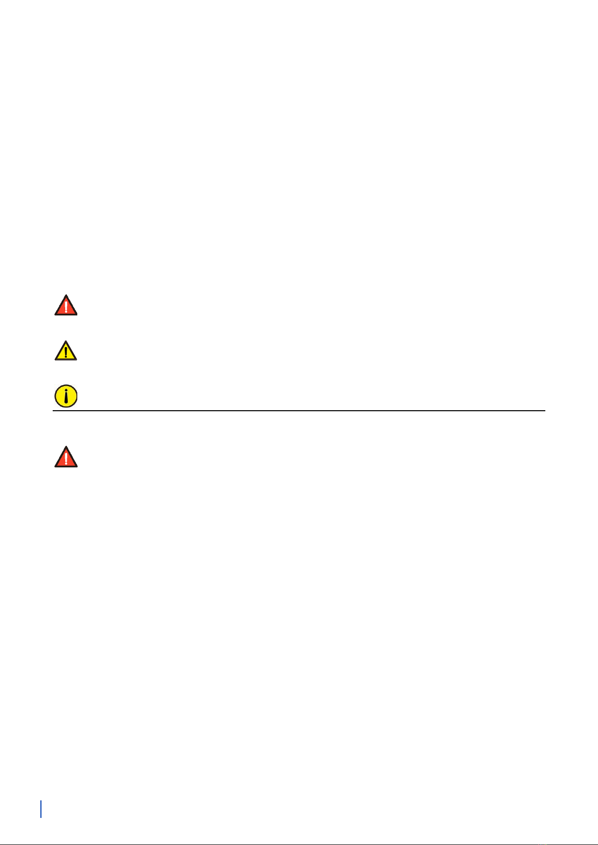
WARNING INFORMATION ........................................................................................................................................................ 4
CAUTION INFORMATION .......................................................................................................................................................... 5
REMARK INFORMATION ........................................................................................................................................................... 6
1.
Powerporter Warranty ........................................................................................................................................... 7
2.
Care and Maintenance ........................................................................................................................................... 7
Environmental Requirements.................................................................................................................................................. 7
Care and Cleaning....................................................................................................................................................................... 7
Maintenance................................................................................................................................................................................ 7
3.
Powerporter Overview ........................................................................................................................................... 8
About Power Porter................................................................................................................................................................... 8
Monitoring Your System ........................................................................................................................................................... 9
Abbreviaon of manual ............................................................................................................................................................ 9
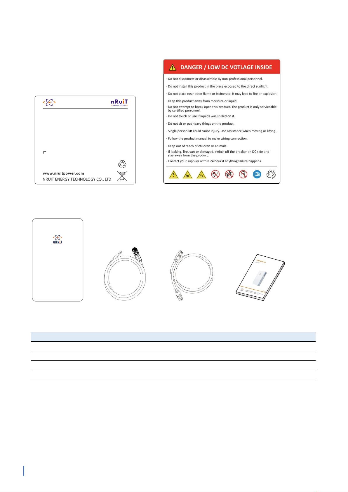
List of Goods ..............................................................................................................................................................................10
Install Fings ............................................................................................................................................................................11
Powerporter Installaon Locaon........................................................................................................................................11
4.
Interface Defini�on............................................................................................................................................... 12
Powerporter interface panel .................................................................................................................................................12
LED status indicators................................................................................................................................................................12
CAN/RS485 Interface Denion ...........................................................................................................................................13
Schemac diagram of connecon with inverter - simple connecon........................................................................14
Schemac diagram of connecon with inverter - recommended connecon.........................................................14
Powerporter power
16
17
cable connecon ................................................................................................................................14
Powerporter on and o................................
...................................................................................................................................................................
..................................................................................................................................................
..........................................................................................................................19
Powerporter Communicaon Interface..............................................................................................................................19
Connect with Inverter..............................................................................................................................................................19
Operang....................................................................................................................................................................................20
Trouble shoong.......................................................................................................................................................................20
Technical Support.....................................................................................................................................................................21
5.
How to deal with an emergency.......................................................................................................................... 21
6.
When the product is turn offand not in use....................................................................................................... 22
7.
System Message ................................................................................................................................................... 22
nRuiT Quality Assurance........................................................................................................................................... 23

4
IMPORTANT SAFETY INSTRUCTIONS
SAVE THESE IMPORTANT SAFETY INSTRUCTIONS
Important: This product should not be used for any purpose other than that described in
this user manual.
Power Porter installan and service require knowledge of high voltage electricity and
should only be performed by nRuiT Cered Installers. Powerporter is not responsible for
injuries or property damage caused by unqualied personnel trying to repair or failing to
follow these instruons correctly. These warnings and caons must be followed when
using Powerporter.
Symbols in This Document
This manual uses the following symbols to highlight important infoon:
WARNING: Indicates a hazardous on which. If not avoided, could result in
death or serious injury.
CAUTION: Indicates that damage or injury may occur. situan which. If not avoided,
it may cause minor injury and/or property damage.
NOTE: Indicates a risk of possible damage to the product.
WARNING INFORMATION:
1.
Powerporter installaon must be carried out only by nRuiT Cered Installers who have
been trained.
2.
In the power regulaon circuit, due to the high voltage, there is a high possibility of
electric shock or severe burns.
3.
High voltage on AC and DC cables. There is a risk of death from electric shock or serious
injury.
4.
There are potenl dangers such as death or serious injury caused by re, high pressure
or explosion caused by this product, if you have not read or do not fully understand the
appropriate prevenve measures.
5.
Do not placmmable and explosive materials near the product.
6.
Do not place any objects on the product during operon.
7.
All the work of PV, power supply regulan and baery system must be completed by
qualied personnel.
8.
Electrical installon must comply with local and nanal electrical safety standards.

5
9.
Wear rubber gloves and protece clothing (protece glasses and boots) when
working on high-voltage / high-current systems (such as PCS and baery systems).
10.
Please do not remove the product cover, there is a risk of electric shock, and there are
no user-usable parts inside. Request service from qualied and approved service
technicians. Do not touch uninsulated wires.
11.
In the event of a failure, the system cannot be restarted. Product repairs must be
performed by qualied personnel or authorized support center personnel.
CAUTION INFORMATION:
12.
The Powerporter and its accessories are contained in this box, the total weight is too
large. Because the product is too heavy, it may cause serious injury. Therefore, special
care must be taken when handling. Make sure that at least two people deliver and move
the package.
13.
Do not use damaged, cracked or frayed cables and connectors. Protect the cable from
physical or mechanical damage, such as the cable being twisted, twisted, clamped,
closed on the door, or trampled by someone. Check the cable of your product regularly.
If its appearance shows damage or deterioran, stop using this product and contact a
qualied person to replace the cable.
14.
Make sure that the product you are connecng is grounded to prevent possible electric
shock. Do not apt to achieve grounding by connecg the product to telephone
lines, lightning rods, or gas pipes.
15.
If the Powerporter is defece, cracked, broken or otherwise damaged or inoperable,
please do not use the Powerporter again.
16.
This product should not come into contact with water (drip or splash), and should not
place objects lled with liquids such as vases on this product.
17.
To prevent the risk of re or electric shock, do not expose this product to rain or
moisture.
18.
Keep out of reach of children or animals.
19.
Products must be handled in accordance with local regulans.
20.
The electrical installan of this device must be carried out by an electrician or
technician with PCS qualican.
21.
To avoid radio interference, all accessories (such as smart meters) connected to the
product must be suitable for resideal, commercial and light industrial areas.
22.
Connect the DC + and DC- cables to the correct DC + and DC- terminals on the product.

6
23.
Do not step on the product or product packaging. The product may be damaged.
24.
Do not discard the baery in re. The baery may explode.
25.
Do not open or damage the baery. The electrolyte released may be toxic and harmful
to the skin and eyes.
26.
Baeries are in danger of electric shock and large current discharge during short circuit.
Pay nn to the following when installing the baery.
a ) Disassemble watches, rings or other metal objects.
b ) Use tools with insulated handles.
c ) Wear insulated gloves and boots.
d ) Do not place tools or metal parts on top of the baery.
REMARK INFORMATION:
27.
Before connecg, please make sure that the open circuit voltage of the photovoltaic
array is within the acceptable range of the inverter to which the product is adapted,
otherwise the product may be damaged.
28.
Never use any solvents, abrasives or corrosive substances to clean this product.
29.
Do not store or place any objects on the product. It may cause serious defects or
malfuncns.
30.
Before connecg the product to the inverter terminal, make sure that the product is
turned o, the inverter is turned the mains and PV channels are disconnected.
31.
The wiring terminal of the Powerporter product is only allowed to be connected to the
adaptable inverter. Do not connect this product directly to the AC power supply or
generator. Conneng the product to other external devices may cause serious damage
to the device.
32.
The product transporton process should be as stable as possible, to avoid the product
in the environment of severe vibron.
33.
The supply of products should be performed or supervised by personnel with baery
knowledge and necessary precauns.

7
1.
Powerporter Warranty
For specic warranty details, see the ached page of this document.
For more informan, please refer to the Powerporter Warranty in your region.
www.nruitpower.com.
2.
Care and Maintenance
Environmental Requirements
Powerporter can charge and discharge within the operng temperature range specied
below. In extreme temperature ranges, Powerporter may limit the power of the baery
when charging or discharging to improve baery life.
Baery Pack Operng Temperature
Charging: 0
℃
to 45
℃
Discharging: -20℃to 45℃
Baery Pack Storage Temperature
-10
℃
to 45
℃
Remarks: The power porter needs to keep the ambient temperature within the range
of 0℃~ 45℃during startup.
Care and Cleaning
If installed outdoors, please ensure that there are no leaves and other debris around the
Powerporter to maintain oprw.
CAUTION: Do not lean, stack, or hang anything around Powerporter and from wires
to Powerporter.
CAUTION: When cleaning the Powerporter, use a so lint-free cloth.
It is recommended to use dry and s cloth, if necessary, only moisten with mild
water.
CAUTION: Do not use cleaning solvents to clean Powerporter, or expose Powerporter
to ammable or harsh chemicals or vapors.
Maintenance
The only maintenance required by the user for the Powerporter is to keep the Powerporter
free of debris.

8
3.
Powerporter Overview
About Power Porter
This product is mainly combined with inverter, photovoltaic (PV) and related accessories to
build resideal energy storage system. The system is used to store the power generated
by PV to the connected baery and convert the direct current (DC) generated by the
connected baery into alternag current (AC) and provide it to the home grid.
(Note: The actual Resideal ESS may also include electrical equipment such as
distribun boxes and metering meters)
Powerporter is a lithium-ion baery that can store electrical energy and outputs DC
current. Powerporter only maintains electrical connecn with the inverter. The electrical
energy generated by the PV is converted by the inverter Dc to DC and stored in the
connected Powerporter. When Powerporter is needed, Powerporter’s electrical energy is
converted by the inverter DC to AC and transmied to the home grid to provide power for
household appliances.
The main funcn of the home energy storage system depends on the inverter.
Powerporter is a device that stores electrical energy.
Funons of home ESS:
34.
Self-producn and sales of electrical energy
Use solar power and Power Porter to reduce the dependence on the grid and store
electricity during the day for night use.
35.
Backup power
When the power grid is out of power, it can be seamlessly switched to Power Porter as

9
a backup power source to protect your home from power outages.
36.
Sell electrical energy
The electrical energy generated by the photovoltaic array can be stored in a connected
Powerporter or sold to an energy supply company.
37.
O-grid power supply
The system can be connected to diesel generators to ensure uninterrupted power
supply in areas without city power (such as islands and remote mountain areas).
(Note: The scheduling management of electrical energy in the system depends on the
inverter. Powerporter is commied to being coble with a variety of inverters. The
inverter you use does not necessarily contain all the above funcns)
Monitoring Your System
Using the app, you can monitor system operon from your mobile device, including the
following:
Real- power usage
Energy con history
Relve amounts of energy used from solar, grid, and Powerporter storage
Abbrevion of manual
Abbrev
n
Full Name
Explanon
ESS
Energy Storage System
System for storing energy to baery and
using
energy stored in baery.
PV
Photovoltaic
Photovoltaic system that converts solar
energy
into direct current.
SOC
State of charge
Current baery level
BMS
Baery Management System
Lithium baery management system
DC
Direct Current
-
AC
Alternang Current
-

10
Product Label and Warning Label
List of Goods
Powerporter 15.0 Power Cables×4 COM Cable×1 User Manual×1
No
.
Project
Explanon
1
Powerporter 15.0
Energy storage baery.
2
Power Cables
×
4
Connect with the inverter to carry out power transmission with it.
3
COM Cable
×
1
Connect with inverter and communicate with it
4
User Manual
×
1
-
Model Name:
Battery Yype:
Rated Energy:
Capacity / Voltage:
charge Voltage:
Max. Continuous DC Power:
Series Number:
Powerporter 15.0
Li-ion / LiFePO4
15.46 kwh
302Ah / 51.2V
51.5V-54V
10Kw

11
Install Fings
Floor mount
Powerporter Installaon Locon
The product installaon must meet the requirements described below.
•This product is recommended for indoor use. If the product is installed
outdoors, it must be ensured that the product is not exposed to direct
sunlight, wetted by liquid, or blown by strong wind under any
circumstances.
•It is recommended to install this product in the place where photovoltaic
cables, mains cables and capacity are arranged.
•This product is only suitable for vertical wall-to-wall installation. Do not
lay this product on the ground.
•The mounting surface must be able to bear this weight. Product (~53kg).
•The suitable operating temperature of the product is 0℃~45℃.
•Do not install this product in direct sunlight.
•Install the product in a clean and cool room.
•This product must not be installed or used at an altitude of more than
2000 meters.
Do not install this product in the place where frequent flooding occurs.
Do not install this product in a bathroom with high humidity.
This product generates low noise at a specific time, and the installation location needs
to consider sound insulation.
The noise level may vary depending on the installation location.
Do not install the product where there is vibration.
Do not install this product in the place with ammonia, corrosive steam, acid or salt.
Installed out of the reach of children and pets.
Do not install this product in places and environments where large amounts of dust
are likely to accumulate.

12
4.
Interface Defini�on
Powerporter interface panel
No
Project
Explanon
12
+
Posive
13
-
negave
14
GND
Ground
15
POWER
Power on/o
LED status indicators
No
Project
Explanon
1
PAR_A
Parallel Port A
2
PAR_B
Parallel Port B
3
COM
DEBUG
4
CAN
Communicaon with Inverter
5
RS485
Communicaon with Inverter
6
DRY
Dry contact
7
ADR
Address denion
8
RST
Product reset
9
RUN
Run LED
10
ALM
Alarm LED
11
SOC LED
SOC LED

13
●●●●
Ba
ery
Stat
us
S
O
C
POW
ER
RUN
ALM
SOC
LED
●
●
●
●
●
●
●
●
●
Power
o
/
●
●
●
●
●
●
●
●
●
Standb
y
83%≤SOC≤
100%
●
Blinki
ng
●
●
●
●
●
●
●
66%
≤
SOC
<
83%
●
Blinki
ng
●
●
●
●
●
●
●
50%≤SOC<66%
●
Blinki
ng
●
●
●
●
●
●
●
33%
≤
SOC
<
50%
●
Blinki
ng
●
●
●
●
●
●
●
16%≤SOC<33%
●
Blinki
ng
●
●
●
●
●
●
●
0%
<
SOC
<
16%
●
Blinki
ng
Blinki
ng
●
●
●
●
●
●
SOC = 0 %
●
Blinki
ng
Blinki
ng
●
●
●
●
●
●
Charge
SOC = 100%
●
●
●
●
●
●
●
●
●
83%≤SOC<
100%
●
●
●
●
●
●
●
●
Blinki
ng
66%
≤
SOC
<
83%
●
●
●
●
●
●
●
Blinki
ng
●
50%≤SOC<66%
●
●
●
●
●
●
Blinki
ng
●
●
33%
≤
SOC
<
50%
●
●
●
●
●
Blinki
ng
●
●
●
16%≤SOC<33%
●
●
●
●
Blinki
ng
●
●
●
●
0%
<
SOC
<
16%
●
●
Blinki
ng
Blinki
ng
●
●
●
●
●
Discharg
e
83%≤SOC<
100%
●
Blinki
ng
●
●
●
●
●
●
●
66%
≤
SOC
<
83%
●
Blinki
ng
●
●
●
●
●
●
●
50%≤SOC<66%
●
Blinki
ng
●
●
●
●
●
●
●
33%
≤
SOC
<
50%
●
Blinki
ng
●
●
●
●
●
●
●
16%≤SOC<33%
●
Blinki
ng
●
●
●
●
●
●
●
0%
<
SOC
<
16%
●
Blinki
ng
Blinki
ng
●
●
●
●
●
●
SOC = 0 %
●
●
●
●
●
●
●
●
●
Protec
on
/
●
●
●
●
●
●
●
●
●
Failure
/
●
●
●
●
●
●
●
●
●
CAN/RS485 Interface Deni
Pin Denion
C
A
N
RS4
85
Pin
Dene
Pi
n
1
、
2
、
3
、
6
、8
/
1
、
8
485-B
4
CAN-H
2
、
7
485-A
5
CAN-L
3
、
6
GND
7
CAN-
GND
4
、
5
N
C

14
Schc diagram of connecn with inverter - recommended conn
Connect to The Inverter
Schc diagram of connecn with inverter - simple connecon
ec
Powerporter power cable connec
The po and negae poles of the Powerporter adopt a quick-plug interface, and the
po and nega poles can be disguished by color (orange indicates the po pole,
black indicates the negative pole), and the installer can directly connect the power cables
to the pond negve poles of the product when wearing protece gloves.
The power cable is connected with the Powerporter through a quick-plug interface, and
connected with the inverter through a ring terminal.
Circuit Breaker
200A

15
Insert the ring terminal of the power cables into the baery connecon port of the inverter,
and ensure that the bolts are htened with a torque of 2 ~ 3N·m. Make sure the polarity
of the bary charge is properly connected, and the ring terminal is ghtened with the
inverter end.
Power cables connecon steps:
Conrm that the inverter mains line is open and the PV line is open. Conrm that
Powerporter is shut down.
The ring terminal of the wiring cables is connected to the posive and negae poles
of the DC terminal of the inverter.
The negae quick connector is connected to the negae port of Powerporter.
The pouick connector is connected to the poe port of the Powerporter.
Warning: Before the installan of the power cables, the Powerporter and the
inverter must be turned .
Power cables disconneon steps:
Make sure the mains line is open, and the PV line is open.
Turn othe inverter switch.
Press the POWER buon to turns oowerporter.
Remove the quick plug connector of the negae power cables.
Remove the quick plug connector of the por cables.
Remove the ring terminal of the power cables.
Warning: Follow the steps strictly. And make sure the interface is in good contact.
Warning: The installaon and disconneon of the wiring cables should be operated
by qualied installers, and the user must not operate in private.
Warning: The power cables may transmit large currents. Please make sure that the
children cannot touch the power Cable.

16
Two Baand One Inverter
Three Baand One Inverter
Battery No.1 Battery No.2
ON DIP
ADR Button
Set “1”
1234
ON DIP
1 2 3 4
ADR Button
Set “2”
PAR_A OUT
RS485/CAN IN
PAR_A IN
RS485/CAN OUT
①
②
③ ④
+
+
-
-
Parallel Box Parallel Box
+
-
ON DIP
ADR Button
Set “1”
1234
ON DIP
1 2 3 4
ADR Button
Set “2”
PAR_A OUT
PAR_B OUT
RS485/CAN IN
PAR_B IN
PAR_A IN
RS485/CAN OUT
①
③
④ ⑤
+
+
-
-
Parallel Box Parallel Box
+
-
Battery No.1 Battery No.2 Battery No.3
②
ADR Button
Set “3”
ON DIP
1234
⑥
+
-

Four Baand Two Inverter
Inverter
No.1
Inverter
No.2
③
④
⑨
RS485/CAN INOUT
RS485/CAN IN
+-
-+-
ADR Button
Set “4”
ON DIP
1234
Parallel Box Parallel Box
ON DIP
ADR Button
Set “1”
1234
ON DIP
1 2 3 4
ADR Button
Set “2”
PAR_A OUT
PAR_A OUT
PAR_B OUT PAR_B IN
PAR_A IN PAR_A IN
RS485/CAN OUT
①
⑤ ⑥
+
-
+
-
Battery No.1 Battery No.2 Battery No.3 Battery No.4
②
ADR Button
Set “3”
ON DIP
1234
⑦ ⑧
+
-
+
-
17

Compa�bility List of nRuiT ESS and Inverters
Inverter Brand
Gro
LuxPower
LuxPower
TBB
Deye
GoodWe
MEGAREVO
SRNE
Inverter Type
SPF5000 ES & SPF5000 HVM
SNA5000
LXP-5K Hybrid
Apollo Max 3.0&5.0
SUN-5K-SG03LP1-EU
GW5048D-ES
R5KLNA
HF4850S80
CAN
CAN
CAN
CAN
CAN
CAN
CAN
RS485
The following inverter brands have been tested by nruit laboratory and can be perfectly compa
18

19
Powerporter on and o
Startup steps:
Make sure the power cable is properly connected
Press the POWER buon.
Product boot
Remarks: Before the product is turned on, the internal relay of the baery will produce
sound when it is switched on / o, which is normal.
Shutdown steps:
Make sure the power cable is disconnected.
Press the POWER buon.
Product shutdown.
Remarks: Before the product is turned , the internal relay of the baery will produce
sound when it is switched on / o, which is normal.
Warning: The power-on and power- acns of the POWER buon are not
emergency operons for security incidents. If there is a safety problem in the home
energy storage system, please disconnect the leakage switch and isolan switch (in
the distribun box) in e. (Conr required).
Powerporter Communican Interface
Both CAN and RS485 interfaces are responsible for the communican with the inverter,
which is determined according to the adaptable inverter. See CAN/RS485 interface
den table.
Connect with Inverter
Ensure that the maximum conuous charge and discharge power of DC terminal is
less than 5000W during Powerporter operaon.

20
Opera
The inverter provides control and monitoring capabies through the applicon program.
During normal operaon, the Powerporter is controlled by the inverter, and the power
buon of the Powerporter should remain on.
Warning: Do not try to use third-party tools and diagnosc tools to communicate
with Powerporter between Powerporter and the inverter.
Trouble ng
If the system is not working properly, please perform the following steps:
Warning: Powerporter and inverter cannot be repaired by users, and must be
repaired by ceed installers.
Warning: If the Powerporter failure causes de and cannot be resolved in
please report to nRuiT or nRuiT authorized service partner in If not
reported to nRuiT or nRuiT authorized service partner within 2 weeks ar the
failure, the warranty is invalid.
38.
If you cannot communicate with the inverter through the applicon, make sure that
the Internet connection is normal.
39.
If neither the inverter nor the power switch responds:
•Turn the inverter
•C all input and output circuit breakers in the distribuon box
•Press the POWER buon to tur Powerporter
•Wait at least one minute
•Press the POWER buon to turn on the Powerporter
•Close the inverter switch and all input and output circuit breakers.
Note: If an event (such as a thunderstorm) causes the system to become unresponsive. Do
the following:
1.
Turn the inverter.
2.
Open all input and output circuit breakers in the distribun box.
3.
Make sure there is no electrical connecn with Powerporter.
4.
Press POWER buto close Powerporter.
5.
Contact nRuiT support or nRuiT authorized dealer for help.
Table of contents
Other nRuiT Camera Accessories manuals
Popular Camera Accessories manuals by other brands

Sanyo
Sanyo VA-LANC100 instruction manual

Preston Cinema Systems
Preston Cinema Systems FI+Z manual

SEC
SEC CELLYTE 6-12TLG Installation and operating instructions

Sony
Sony MPK-DVF O operating instructions

Bioenno Power
Bioenno Power BLF-1209T Instructions for use

Big Game Treestands
Big Game Treestands The Apex CR9000 instruction manual