nRuiT PowerPorter 5.0 User manual

PowerPorter 5.0
User Manual
Version 2.0
nRuiT strongly advises to take due care in following the User manual. A
warranty claim is invalid if damage is caused by human error, inconsistent.

For the latest Powerporter documents including the Warranty, visit www.xinrex.com.cn.
WARNING
Read this entire document before installing or using Powerporter.
Failure to do so or to follow any of the instructions or warnings in this document
can result in electrical shock, serious injury, or death, or can damage
Powerporter.
PRODUCT SPECIFICATIONS
This manual applies to the product: Powerporter 5.0
All specifications and descriptions contained in this document are verified to be accurate at
the time of printing. However, because continuous improvement is a goal at nRuiT, we
reserve the right to make product modifications at any time.
The images provided in this document are for demonstration purposes only. Depending on
product version, details may appear slightly different.
ERRORS
To communicate any inaccuracies in this manual, send an email to:
ELECTRONIC DEVICE: DO NOT THROW AWAY
Proper disposal of batteries is required. Refer to your local distributor for
disposal requirements.
MADE IN CHINA
© 2023 nRuiT Energy All Rights Reserved
All information in this document is subject to copyright and other intellectual property rights of
nRuiT. This material cannot be modified or copied; additional information may be provided
upon request.
The following are trademarks or registered trademarks of nRuiT Energy in China and Other
Countries.
nRuiT
Powerporter
All other trademarks contained in this document are the property of their respective owners
and their use herein does not imply sponsorship or endorsement of their products or services.
The unauthorized use of any trademark displayed in this document or on the product is strictly
prohibited.

TABLE OF CONTENTS
IMPORTANT SAFETY INSTRUCTIONS....................................................................................................1
Symbols In This Document.................................................................................................................................1
WARNING INFORMATION ..................................................................................................................................1
CAUTION INFORMATION....................................................................................................................................2
REMARK INFORMATION .....................................................................................................................................3
1. Powerporter Warranty .................................................................................................................................3
2. Care And Maintenance .................................................................................................................................4
Environmental Requirements............................................................................................................................4
Care And Cleaning.................................................................................................................................................4
Maintenance ............................................................................................................................................................4
3. Powerporter Overview .................................................................................................................................4
About Power Porter..........................................................................................................................................4-5
Monitoring Your System......................................................................................................................................6
Abbreviation Of Manual ......................................................................................................................................6
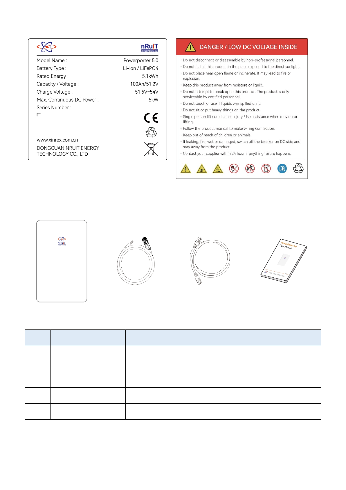
Product Label And Warning Label..................................................................................................................7
List Of Goods...........................................................................................................................................................7
Install Fittings...........................................................................................................................................................8
Powerporter Installation Location...................................................................................................................8
4. Interface Definition..........................................................................................................................................9
Powerporter Interface Panel..............................................................................................................................9
LED Status Indicators.........................................................................................................................................10
CAN/RS485 Interface Definition ....................................................................................................................11
5. Connect To The Inverter...........................................................................................................................11
Schematic Diagram Of Connection With Inverter - Simple Connection .......................................11
Schematic Diagram Of Connection With Inverter - Recommended Connection......................12
Powerporter Power Cable Connection .......................................................................................................12
Parallel Operation.........................................................................................................................................13-14
Compatible Inverter Brand ..............................................................................................................................15
Powerporter On And Off ..................................................................................................................................16
Powerporter Communication Interface ......................................................................................................17
Operating................................................................................................................................................................17
Trouble Shooting.................................................................................................................................................17
Technical Support ...............................................................................................................................................17
6. How To Deal With An Emergency.....................................................................................................18
7. When The Product Is Turn Off And Not In Use ......................................................................19
8. System Message..............................................................................................................................................19
nRuiT Warranty Policy......................................................................................................................................20

1
IMPORTANT SAFETY INSTRUCTIONS
SAVE THESE IMPORTANT SAFETY INSTRUCTIONS
Important: This product should not be used for any purpose other than that described in this
user manual.
Powerporter installation and service require knowledge of high voltage electricity and should
only be performed by nRuiT Certified Installers. Powerporter is not responsible for injuries or
property damage caused by unqualified personnel trying to repair or failing to follow these
instructions correctly. These warnings and cautions must be followed when using Powerporter.
Symbols In This Document
This manual uses the following symbols to highlight important information:
WARNIN
G
Indicates a hazardous situation which. If not avoided, could result in death or
serious injury.
CAUTION
Indicates that damage or injury may occur. situation which. If not avoided, it may
cause minor injury and/or property damage.
NOTE
Indicates a risk of possible damage to the product.
WARNING INFORMATION
Powerporter installation must be carried out only by nRuiT Certified Installers who have
been trained.
In the power regulation circuit, due to the high voltage, there is a high possibility of electric
shock or severe burns.
High voltage on AC and DC cables. There is a risk of death from electric shock or serious
injury.
There are potential dangers such as death or serious injury caused by fire, high pressure or
explosion caused by this product, if you have not read or do not fully understand the
appropriate preventive measures.
Do not place flammable and explosive materials near the product.
Do not place any objects on the product during operation.
All the work of PV, power supply regulation and battery system must be completed by
qualified personnel.

2
Electrical installation must comply with local and national electrical safety standards.
Wear rubber gloves and protective clothing (protective glasses and boots) when working
on high-voltage / high-current systems (such as PCS and battery systems).
Please do not remove the product cover, there is a risk of electric shock, and there are no
user-usable parts inside. Request service from qualified and approved service technicians.
Do not touch uninsulated wires.
In the event of a failure, the system cannot be restarted. Product repairs must be
performed by qualified personnel or authorized support center personnel.
CAUTION INFORMATION
The Powerporter and its accessories are contained in this box, the total weight is too large.
Because the product is too heavy, it may cause serious injury. Therefore, special care must
be taken when handling. Make sure that at least two people deliver and move the package.
Do not use damaged, cracked or frayed cables and connectors. Protect the cable from
physical or mechanical damage, such as the cable being twisted, twisted, clamped, closed
on the door, or trampled by someone. Check the cable of your product regularly. If its
appearance shows damage or deterioration, stop using this product and contact a
qualified person to replace the cable.
Make sure that the product you are connecting is grounded to prevent possible electric
shock. Do not attempt to achieve grounding by connecting the product to telephone lines,
lightning rods, or gas pipes.
If the Powerporter is defective, cracked, broken or otherwise damaged or inoperable,
please do not use the Powerporter again.
This product should not come into contact with water (drip or splash), and should not
place objects filled with liquids such as vases on this product.
To prevent the risk of fire or electric shock, do not expose this product to rain or moisture.
Keep out of reach of children or animals.
Products must be handled in accordance with local regulations.
The electrical installation of this device must be carried out by an electrician or technician
with PCS qualification.
To avoid radio interference, all accessories (such as smart meters) connected to the
product must be suitable for residential, commercial and light industrial areas.
Connect the DC+ and DC- cables to the correct DC+ and DC- terminals on the product.
Do not step on the product or product packaging. The product may be damaged.

3
Do not discard the battery in a fire. The battery may explode.
Do not open or damage the battery. The electrolyte released may be toxic and harmful to
the skin and eyes.
Batteries are in danger of electric shock and large current discharge during short circuit.
Pay attention to the following when installing the battery.
1. Disassemble watches, rings or other metal objects.
2. Use tools with insulated handles.
3. Wear insulated gloves and boots.
4. Do not place tools or metal parts on top of the battery.
REMARK INFORMATION
Before connecting, please make sure that the open circuit voltage of the photovoltaic array
is within the acceptable range of the inverter to which the product is adapted, otherwise
the product may be damaged.
Never use any solvents, abrasives or corrosive substances to clean this product.
Do not store or place any objects on the product. It may cause serious defects or
malfunctions.
Before connecting the product to the inverter terminal, make sure that the product is
turned off, the inverter is turned off and the mains and PV channels are disconnected.
The wiring terminal of the Powerporter product is only allowed to be connected to the
adaptable inverter. Do not connect this product directly to the AC power supply or
generator. Connecting the product to other external devices may cause serious damage to
the device.
The product transportation process should be as stable as possible, to avoid the product in
the environment of severe vibration.
The supply of products should be performed or supervised by personnel with battery
knowledge and necessary precautions.
1. Powerporter Warranty
For specific warranty details, see the attached page of this document.
For more information, please refer to the Powerporter Warranty in your region.
www.xinrex.com.cn

4
2. Care And Maintenance
Environmental Requirements
Powerporter can charge and discharge within the operating temperature range specified
below. In extreme temperature ranges, Powerporter may limit the power of the battery when
charging or discharging to improve battery life.
Battery Pack Operating Temperature
Charging: 0℃ to 55℃
Discharging: -20℃ to 55℃
Battery Pack Storage Temperature
-10℃ to 45℃
REMARK
S
The Powerporter needs to keep the ambient temperature within the range of
0℃~45℃ during startup.
Care And Cleaning
If installed outdoors, please ensure that there are no leaves and other debris around the
Powerporter to maintain optimal airflow.
CAUTION
Do not lean, stack, or hang anything around Powerporter and from wires to
Powerporter.
CAUTION
When cleaning the Powerporter, use a soft, lint-free cloth.
It is recommended to use dry and soft cloth, if necessary, only moisten with mild
water.
CAUTION
Do not use cleaning solvents to clean Powerporter, or expose Powerporter to
flammable or harsh chemicals or vapors.
Maintenance
The only maintenance required by the user for the Powerporter is to keep the Powerporter free
of debris.
3. Powerporter Overview
About Power Porter
This product is mainly combined with inverter, photovoltaic (PV) and related accessories to
build residential energy storage system. The system is used to store the power generated by
PV to the connected battery and convert the direct current (DC) generated by the connected
battery into alternating current (AC) and provide it to the home grid.

5
(Note: The actual Residential ESS may also include electrical equipment such as distribution
boxes and metering meters)
Powerporter is a lithium-ion battery that can store electrical energy and outputs DC current.
Powerporter only maintains electrical connection with the inverter. The electrical energy
generated by the PV is converted by the inverter Dc to DC and stored in the
connected Powerporter. When Powerporter is needed, Powerporter's electrical energy is
converted by the inverter DC to AC and transmitted to the home grid to provide power for
household appliances.
The main function of the home energy storage system depends on the inverter. Powerporter is
a device that stores electrical energy.
Functions of home ESS:
Self-production and sales of electrical energy
Use solar power and Power Porter to reduce the dependence on the grid and store
electricity during the day for night use.
Backup power
When the power grid is out of power, it can be seamlessly switched to Power Porter as
a backup power source to protect your home from power outages.
Sell electrical energy
The electrical energy generated by the photovoltaic array can be stored in a connected
Powerporter or sold to an energy supply company.
Off-grid power supply
The system can be connected to diesel generators to ensure uninterrupted power supply
in areas without city power (such as islands and remote mountain areas).
(Note: The scheduling management of electrical energy in the system depends on the inverter.
Powerporter is committed to being compatible with a variety of inverters. The inverter you use
does not necessarily contain all the above functions)

6
Monitoring Your System
Using the app, you can monitor system operation from your mobile device, including the
following:
Real-time power usage
Energy consumption history
Relative amounts of energy used from solar, grid, and Powerporter storage
Abbreviation Of Manual
Abbreviation
Full Name
Explanation
ESS
Energy Storage System
System for storing energy to battery and using
energy stored in battery.
PV
Photovoltaic
Photovoltaic system that converts solar energy
into direct current.
SOC
State of charge
Current battery level
BMS
Battery Management
System
Lithium battery management system
DC
Direct Current
-
AC
Alternating Current
-

7
Product Label And Warning Label
List Of Goods
Powerporter
Power Cables×2
COM Cable×1
User Manual×1
No.
Project
Explanation
1
Powerporter
Energy storage battery.
2
Power Cables×2
Connect with the inverter to carry out power transmission
with it.
3
COM Cable×1
Connect with inverter and communicate with it.
4
User Manual×1
-

8
Install Fittings
Support_1
Support_2×2
Floor-Mount
Wall-Mount
Powerporter Installation Location
The product installation must meet the requirements described below.
This product is recommended for indoor use. If the product
is installed outdoors, it must be ensured that the product is
not exposed to direct sunlight, wetted by liquid, or blown
by strong wind under any circumstances.
It is recommended to install this product in the place where
photovoltaic cables, mains cables and capacity are arranged.
This product is only suitable for vertical wall-to-wall
installation. Do not lay this product on the ground.
The mounting surface must be able to bear this weight.
Product (~51kg).
The suitable operating temperature of the product is
0℃~45℃.
Do not install this product in direct sunlight.
Install the product in a clean and cool room.
This product must not be installed or used at an altitude of
more than 2000 meters.
Do not install this product in the place where frequent
flooding occurs.
Do not install this product in a bathroom with high humidity.
This product generates low noise at a specific time, and the installation
location needs to consider sound insulation.
The noise level may vary depending on the installation location.
Do not install the product where there is vibration.
Do not install this product in the place with ammonia, corrosive steam,
acid or salt.
Installed out of the reach of children and pets.
Do not install this product in places and environments where large
amounts of dust are likely to accumulate.

9
4. Interface Definition
Powerporter Interface Panel
No
Project
Explanation
1
PAR_A
Parallel Port A
2
PAR_B
Parallel Port B
3
COM
DEBUG
4
CAN
Communication with Inverter
5
RS485
Communication with Inverter
6
DRY
Dry contact
7
ADR
Address definition
8
RST
Product reset
9
RUN
Run LED
10
ALM
Alarm LED
11
SOC LED
SOC LED
No
Project
Explanation
12
+
Positive
13
-
negative
14
GND
Ground
15
POWER
Power on/off

10
LED Status Indicators
●●●●
POWER
RUN
ALM
SOC LED
Battery Status
SOC
●
●
●
●
●
●
●
●
●
Power off
/
●
●
●
●
●
●
●
●
●
83%≤SOC≤100%
●
Blinking
●
●
●
●
●
●
●
66%≤SOC<83%
●
Blinking
●
●
●
●
●
●
●
50%≤SOC<66%
●
Blinking
●
●
●
●
●
●
●
33%≤SOC<50%
●
Blinking
●
●
●
●
●
●
●
16%≤SOC<33%
●
Blinking
●
●
●
●
●
●
●
0%<SOC <16%
●
Blinking
Blinking
●
●
●
●
●
●
Standby
SOC = 0 %
●
Blinking
Blinking
●
●
●
●
●
●
SOC = 100%
●
●
●
●
●
●
●
●
●
83%≤SOC<100%
●
●
●
●
●
●
●
●
Blinking
66%≤SOC<83%
●
●
●
●
●
●
●
Blinking
●
50%≤SOC<66%
●
●
●
●
●
●
Blinking
●
●
33%≤SOC<50%
●
●
●
●
●
Blinking
●
●
●
16%≤SOC<33%
●
●
●
●
Blinking
●
●
●
●
Charge
0%<SOC <16%
●
●
Blinking
Blinking
●
●
●
●
●
83%≤SOC<100%
●
Blinking
●
●
●
●
●
●
●
66%≤SOC<83%
●
Blinking
●
●
●
●
●
●
●
50%≤SOC<66%
●
Blinking
●
●
●
●
●
●
●
33%≤SOC<50%
●
Blinking
●
●
●
●
●
●
●
16%≤SOC<33%
●
Blinking
●
●
●
●
●
●
●
0%<SOC <16%
●
Blinking
Blinking
●
●
●
●
●
●
Discharge
SOC = 0 %
●
●
●
●
●
●
●
●
●
Protection
/
●
●
●
●
●
●
●
●
●
Failure
/
●
●
●
●
●
●
●
●
●

11
CAN/RS485 Interface Definition
Pin Definition
CAN
RS485
Pin
Define
Pin
Define
1、2、3、6、8
NC
9、16
RS485-B1
5
CAN-L
10、15
RS485-A1
4
CAN-H
11、14
GND
7
GND
12、13
NC
5. Connect To The Inverter
Schematic Diagram Of Connection With Inverter - Simple Connection

12
Schematic Diagram Of Connection With Inverter - Recommended Connection
Powerporter Power Cable Connection
The positive and negative poles of the Powerporter adopt a quick-plug interface, and the
positive and negative poles can be distinguished by color (orange indicates the positive pole,
black indicates the negative pole), and the installer can directly connect the power cables to
the positive and negative poles of the product when wearing protective gloves.
The power cable is connected with the Powerporter through a quick-plug interface, and
connected with the inverter through a ring terminal.
Insert the ring terminal of the power cables into the battery connection port of the inverter,
and ensure that the bolts are tightened with a torque of 2~3Nm. Make sure the polarity of the
battery charge is properly connected, and the ring terminal is tightened with the inverter end.
Power cables connection steps:
① Confirm that the inverter mains line is open and the PV line is open. Confirm that
Powerporter is shut down.
② The ring terminal of the wiring cables is connected to the positive and negative poles of
the DC terminal of the inverter.
③ The negative quick connector is connected to the negative port of Powerporter.
④ The positive quick connector is connected to the positive port of the Powerporter.

13
WARNING
Before the installation of the power cables, the Powerporter and the inverter must
be turned off.
Power cables disconnection steps:
① Make sure the mains line is open, and the PV line is open.
② Turn off the inverter switch.
③ Press the POWER button to turns off Powerporter.
④ Remove the quick plug connector of the negative power cables.
⑤ Remove the quick plug connector of the positive power cables.
⑥ Remove the ring terminal of the power cables.
WARNING
Follow the steps strictly. And make sure the interface is in good contact.
WARNING
The installation and disconnection of the wiring cables should be operated by
qualified installers, and the user must not operate in private.
WARNING
The power cables may transmit large currents. Please make sure that the children
cannot touch the power Cable.
Parallel Operation
Two Battery and One Inverter
① Connect [PAR_A] of battery 1 to
[PAR_A] of battery 2.
② Connect [RS485/CAN] of battery
1 to [RS485/CAN] of inverter.
③ Set the Button-ADR of battery 1
to "1".
④ Set the Button-ADR of battery 2
to "2".

14
Three Battery and One Inverter
① Connect [PAR_A] of battery 1 to [PAR_A] of battery 2.
② Connect [PAR_B] of battery 2 to [PAR_B] of battery 3.
③ Connect [RS485/CAN] of battery 1 to [RS485/CAN] of inverter.
④ Set the Button-ADR of battery 1 to "1".
⑤ Set the Button-ADR of battery 2 to "2".
⑥ Set the Button-ADR of battery 3 to "1" and "2".

15
Four Battery and Two Inverter
① Connect [PAR_A] of battery 1 to [PAR_A]
of battery 2.
② Connect [PAR_B] of battery 2 to [PAR_B]
of battery 3.
③ Connect [PAR_A] of battery 3 to [PAR_A]
of battery 4.
④ Connect [RS485/CAN] of battery 1 to
[RS485/CAN] of inverter 1.
⑤ Set the Button-ADR of battery 1 to "1".
⑥ Set the Button-ADR of battery 2 to "2".
⑦ Set the Button-ADR of battery 3 to "1"
and "2".
⑧ Set the Button-ADR of battery 4 to "3".
⑨ Connect [BMS] of Inverter 1 to [BMS] of
Inverter 2.
Compatible Inverter Brand
The following inverter brands have been tested by nruit laboratory and can be perfectly
compatible with powerporter.
Compatibility List of nRuiT ESS and Inverters
Inverter Brand
Inverter Type
Communicatio
n
SPF5000 ES & SPF5000 HVM
CAN
SPF 5000TL HVM/ HVM-P(WIFI-F)
CAN
SPF 3000TL HVM-24/48(WIFI-F)
CAN
SPF 3000TL LVM-24P /48P(WIFI-F)
CAN
SPF 6/8/10/12000T DVM-MPV(WIFI-F)
CAN
SPF 6/8/10/12000T DVM(WIFI-F)
CAN
Growatt
SPF 5000 US/ES(WIFI-F)
CAN
SUN-3.0K-SG04LP1-24/48-EU
CAN
SUN-3.6/5.0/6.0/8.0K-SG03LP1-EU
CAN
SUN-10/12K-SG02LP1-EU-AM3
CAN
SUN-16K-SG01LP1-EU
CAN
Deye
SUN-5.0/6.0/8.0/10.0/12.0K-SG04LP3-EU
CAN
SNA5000
CAN
LuxPower
LXP-5K Hybrid
CAN
TBB
Apollo Max 3.0&5.0
CAN
GoodWe
GW5048D-ES
CAN

16
R5KLNA
CAN
Megarevo
R6/R8KL1
RS485
SRNE
HF4850S80
CAN
Axpert VM III 1.5KVA/3KVA/5KVA
RS485
Voltronic
Axpert VM 4 3.6KVA/5.6KVA
RS485
Victron
MultiPlus-Il3000VA - 5000VA - 8000VA -
10000VA-15000VA
RS485
AOTAI
AEP-3KS48P/3K6S48P/5KS48P
CAN
INVT
XD3-6kW
CAN
REMARK
S
Ensure that the maximum continuous charge and discharge power of DC terminal is
less than 5000W during Powerporter operation.
Powerporter On And Off
Startup steps:
① Make sure the power cable is properly connected
② Press the POWER button.
③ Product boot
REMARKS
Before the product is turned on, the internal relay of the battery will produce sound
when it is switched on / off, which is normal.
Shutdown steps:
① Press the POWER button.
② Make sure the power cable is disconnected.
③ Product shutdown.
REMARKS
Before the product is turned off, the internal relay of the battery will produce sound
when it is switched on / off, which is normal.
WARNING
The power-on and power-off actions of the POWER button are not emergency
operations for security incidents. If there is a safety problem in the home energy
storage system, please disconnect the leakage switch and isolation switch (in the

17
distribution box) in time. (Confirmation required).
Powerporter Communication Interface
Both CAN and RS485 interfaces are responsible for the communication with the inverter, which
is determined according to the adaptable inverter. See CAN/RS485 interface definition table.
Operating
The inverter provides control and monitoring capabilities through the application program.
During normal operation, the Powerporter is controlled by the inverter, and the power button
of the Powerporter should remain on.
WARNING
Do not try to use third-party tools and diagnostic tools to communicate with
Powerporter between Powerporter and the inverter.
Trouble Shooting
If the system is not working properly, please perform the following steps:
WARNING
Powerporter and inverter cannot be repaired by users, and must be repaired by
certified installers.
WARNING
If the Powerporter failure causes downtime and cannot be resolved in time, please
report to nRuiT or nRuiT authorized service partner in time. If not reported to nRuiT
or nRuiT authorized service partner within 2 weeks after the failure, the warranty is
invalid.
If you cannot communicate with the inverter through the application, make sure that the
Internet connection is normal.
If neither the inverter nor the power switch responds:
1. Turn off the inverter
2. Cut off all input and output circuit breakers in the distribution box
3. Press the POWER button to turn off Powerporter
4. Wait at least one minute
5. Press the POWER button to turn on the Powerporter
6. Close the inverter switch and all input and output circuit breakers.
Note: If an event (such as a thunderstorm) causes the system to become unresponsive. Do the
following:
1. Turn off the inverter.
2. Open all input and output circuit breakers in the distribution box.
3. Make sure there is no electrical connection with Powerporter.
4. Press POWER button to close Powerporter.
5. Contact nRuiT support or nRuiT authorized dealer for help.
Technical Support
If you need further assistance, please contact the nRuiT service team via the support phone in
Table of contents