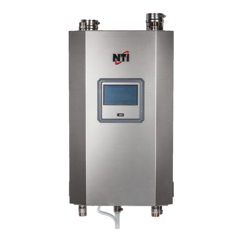
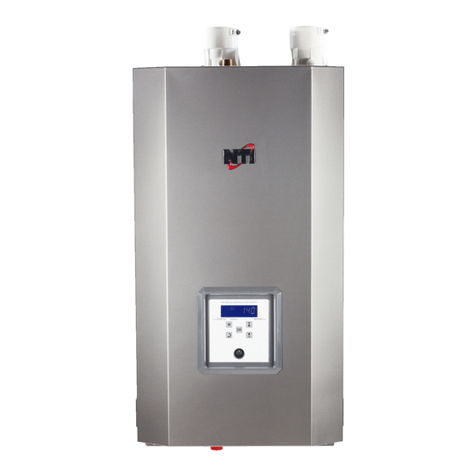
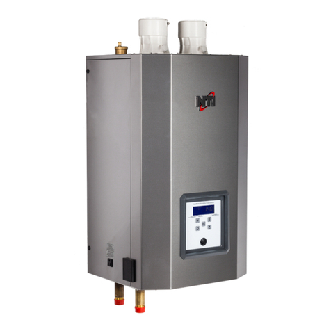
NTI FTG 600 User manual

1
Firetube Giant FTG 600-1400
NATURAL GAS TO LP CONVERSION INSTRUCTIONS:
Version Date: 2017-05-04
Kit Number: 85418-1
NTI boilers are factory equipped to operate with Natural Gas. BEFORE OPERATING WITH PROPANE the
boiler’s gas valve must be adjusted according to these instructions. Use the procedures outlined in these instructions to
fully complete the Natural Gas to LP conversion.
Kit Contents:
Natural Gas to LP Conversion Instructions (p/n 85445)
Natural Gas to LP Conversion Decal (p/n 85418)
These instructions CANNOT be used to convert NTI appliance models not referenced in these
instructions. Contact NTI for the Natural Gas to LP conversion kit and instructions for other
models.
Failure to apply these instructions properly may result in dangerous Carbon Monoxide levels,
fire or explosion leading to property damage, personal injury or death.
ATTENTION: LIQUEFIED PETROLEUM (LP) PROPANE
Liquefied Petroleum (LP) propane gas is heavier than air; therefore, it is imperative that your boiler is not
installed in a pit or similar location that will permit heavier than air gas to collect. Local Codes may require
appliances fueled with LP gas be provided with an approved means of removing unburned gases from the
room. Check your local codes for this requirement.
NTI # 85445
This conversion shall be performed by a qualified service agency in accordance with
the manufacturer’s instructions and all applicable codes and requirements of the
authority having jurisdiction. If the information in these instructions is not followed
exactly, a fire, an explosion or production of carbon monoxide may result causing
property damage, personal injury or loss of life. The qualified service agency is
responsible for the proper application of these instructions. The conversion is not
proper and complete until the operation of the converted appliance is checked as
specified in the manufacturer’s instructions supplied with the kit, which necessitates
the use of a calibrated CO2/O2and CO combustion analyzer.

2
1.0 Adjusting the Gas Valve
The FTG 600, FTG 800, FTG 1200 & FTG 1400 are converted from Natural to LP Gas by
adjusting the Throttle/Input Screw located on the gas valve; unlike most LP conversions an
LP orifice is NOT used.
1. Locate the Throttle/Input Adjustment Screw on the gas valve, see Figure 1-1.
2. Turn the Throttle Screw all the way in (clockwise until it stops).
3. Turn the Throttle Screw counterclockwise (out) ½ of a turn (¾ of a turn for FTG 1400).
4. Proceed to Section 2.0, Gas Valve and Burner Setup, for instructions on how to test the Gas Line Pressure and
perform the Combustion Calibration.
Figure 1-1 Throttle/Input Screw Adjustment
2.0 Gas Valve and Burner Setup
Failure to perform the Gas Valve and Burner Setup correctly may result in incorrect
operation, component failure, property damage, serious injury or death.
Operating Sequence
Prior to commencing the Gas Valve and Burner Setup, perform the following operating sequence check:
1. Turn the supply of gas to the boiler off.
2. Set the thermostat to the highest setting.
3. Ensure the combustion fan pre-purges for at least 30 seconds prior to activating the igniter.
4. Ensure the combustion fan post-purges for at least 60 seconds prior to reactivating the igniter.
5. Set the thermostat to the lowest setting and continue with the Gas Valve and Burner Setup procedure outlined
below.
DO NOT Adjust
Gas Valve
Manifold Pressure Test Port
(located on gas valve outlet
flange)
Throttle / Input Adjustment Screw –
using a 3 mm hex wrench, turn screw
all the way in (clockwise) until it stops,
then turn out (counterclockwise) ½ a
turn (3/4 of a turn for FTG 1400), then
proceed with Combustion Calibration.
Line Pressure Test Port
(located on gas valve inlet
flange)
Venturi
Combustion Blower
Air Filter
Cap (remove to access Throttle
Adjustment Screw)
Low Gas Pres. Switch
(auto-reset)
High Gas Pres. Switch
(manual reset)

3
Gas Line Pressure
The boiler gas valve is equipped with a line pressure test port; see Figure 1-1. Use the following procedure to
measure the gas line pressure to the boiler to ensure if falls within the range given in Table 2-1:
1. Turn the supply of gas to the boiler off.
2. Using a 3/16 in. hex wrench, remove the plug from the flange located at the inlet of the gas valve, identified as
Line Pressure Test Port in Figure 1-1. In place of the plug, install a 1/8 NPT x hose barb adapter, suitable for
connecting the tubing of the gas pressure manometer being used to measure gas line pressure.
3. Slide the gas pressure manometer tubing over the hose barb adapter installed in step 2; connect the other end of
the tubing to gas pressure manometer. Ensure both ends of the tubing make a tight connection.
4. Open the supply of gas to the boiler and check for gas leaks.
5. Observe the line pressure under static conditions and compare it to Table 2-1. The pressure will be greatest under
static conditions.
6. With all other gas appliances in the application running, operate the burner to the maximum firing rate (see Table
2-2) and compare the observed line pressure with Table 2-1. The pressure will be lowest during the maximum
flow of gas.
7. Adjust the gas line pressure to ensure the parameters in Table 2-1 are attained under all conditions (see NOTICE
below). If possible adjust the line pressure to the "Nominal/Desired" value listed in Table 2-1, while the unit is
operating at the maximum modulation rate, see Table 2-2.
8. Continue observing the gas line pressure until the completion of the combustion analyses, in case adjustments
need to be made.
9. Complete pressure testing, turn the gas supply off, and then reinstall the Line Pressure Test Port plug, applying
appropriate thread sealant to the threads prior to installing. Turn gas on and check for leaks.
The line pressure is a function of the gas supply and is affected solely by field provided
parameters such as line size and regulator settings. Under no circumstances can the boiler gas
valve influence or be used to adjust the gas line pressure.
Failure to properly install the Line Pressure Test Port plug will cause a severe leakage of gas,
resulting in a fire or explosion causing property damage, serious injury or death.
Table 2-1 Line Pressure and Combustion Parameters
Gas
Line Pressure (inches w.c.)
CO2(%)*
CO (ppm)
Max.*
Nominal/Desired
Min.
Max.
Min.
Max.
Natural
7
4
10.5
8.7
9.5
175
Propane
11
8
13
10
10.8
175
Notes:
1Combustion calibration must only be performed with the burner operating at maximum modulation rate.
2Combustion values listed are for burner operation at maximum modulation rate; CO2 and CO values will be lower at
minimum modulation rate.
3When tested at minimum modulation rate, the CO2must be 0.5-1.0% lower than CO2at maximum modulation rate.
Table 2-2 Minimum and Maximum Modulation and Input Rates
Model
Min. Modulation Rate (RPM)
Max. Modulation Rate (RPM)
Input Rate (MBH)
Min
Max *
FTG 600
1150
5600
80
600
FTG 800
1150
7450
80
800
FTG 1200
1050
8100
120
1200
FTG 1400
1050
7800
140
1400
* Canada: Altitudes between 2000-4500 ft, de-rate by 10%. Consult local authorities for de-rating for altitudes above 4500ft.
Carbon Monoxide - Never leave the unit operating while producing Carbon Monoxide (CO)
concentrations in excess of 175ppm. Failure to follow this warning may result in serious
injury or death.
Manifold Pressure - DO NOT adjust or measure the Manifold Pressure of the boiler. Correct
manifold pressure is factory set. Field adjustment could result in improper burner operation
resulting in fire, explosion, property damage or death.
Adjustments to the Throttle/Input Adjustment Screw may only be made by a qualified gas
technician, while using a calibrated combustion analyzer capable of measuring CO2and CO.
Adjustments may only be performed if the gas line pressure is maintained above minimum
levels throughout the duration of the test, see Table 2-1. Failure to follow these instructions
may result in serious injury or death.
4
Adjustment
Throttle / Input Screw Adjustments - The boiler is equipped with a Throttle/Input Adjustment Screw, located under
a plastic cap on the top of the Gas Valve; see Figure 1-1. It is used to adjust the flow of gas leaving the gas valve
entering the Venturi and then the combustion air stream. Turn the Throttle screw in (clockwise) to reduce the flow
of gas, make combustion leaner, and reduce the concentration of CO2in the flue gases. Turn the Throttle screw out
(counterclockwise) to increase the concentration of CO2and flow of gas in the combustion air stream. Typical
adjustment required is 0-1/8 of a turn in or out from starting point (see Section 1.0). See Figure 1-1 for Throttle
screw location and Table 2-1 for appropriate CO2levels.
Combustion Calibration - To calibrate burner operation, perform the following procedure using a calibrated
combustion analyzer capable of measuring CO2and CO from Natural and Propane Gas burning boilers:
1. Operate the unit at the maximum modulation rate, see Table 2-2.
2. Ensure the gas line pressure is maintained within tolerance, see Table 2-1.
3. While at the maximum modulation rate, measure the CO2and CO; adjust as necessary, using the Throttle
Screw, to be within the limits listed in Table 2-1.
4. Operate the unit at the minimum modulation rate (see Table 2-2). Ensure the combustion remains smooth
and CO2and CO values are lower than the values obtained during maximum modulation, as per notes in
Table 2-1. If not, do not adjust further, contact NTI for assistance.
Failure to perform the flue gas analysis and adjustment as detailed in this section may result in
erratic and unreliable burner operation, leading to reduced efficiency, increased fuel
consumption, reduced component life, heat exchanger combustion deposits, and general
unsafe operation. Failure to follow these instructions may result in serious injury or death.
3.0 Labeling
As the certified installer of the LP Conversion Kit, you must indicate on the boiler that it has been converted for use
with Propane (LP) Gas:
1. Update Rating Plate Decal –Locate the rating plate decal on the side of the appliance, using a regular ink pen,
check the box next to “Field converted to Propane Gas” and fill in the date; depress hard enough to permanently
etch the decal (see Figure 3-1).
2. Conversion Decal - Fill out the required information on the Conversion Decal (included in this kit) and affix it to
the boiler cabinet adjacent to the rating plate decal, and in a location where it can be easily seen (see Figure 3-2).
Figure 3-1 Update the Rating Plate Decal
Figure 3-2 Conversion Decal
X
March 29, 2016
Throttle/Input Adjustment Screw
Increase gas
Turn Counter Clockwise
Decrease gas
Turn Clockwise
Throttle/Input Adjustment Screw
Increase gas
Turn Counter Clockwise
Decrease gas
Turn Clockwise
John Smith
Other manuals for FTG 600
2
This manual suits for next models
3
Other NTI Boiler manuals
Popular Boiler manuals by other brands

Biasi
Biasi Activ A 12OV Service manual

Worcester
Worcester GreenStar DanesMoor User and care guide

Immergas
Immergas VICTRIX PRO 55 1 A User's installation and operation manual

EnergyLogic
EnergyLogic EL-200B Installation & operation manual

Ariston
Ariston Genus 27 Plus installation instructions

Eco Engineering
Eco Engineering Easypell 16 installation manual