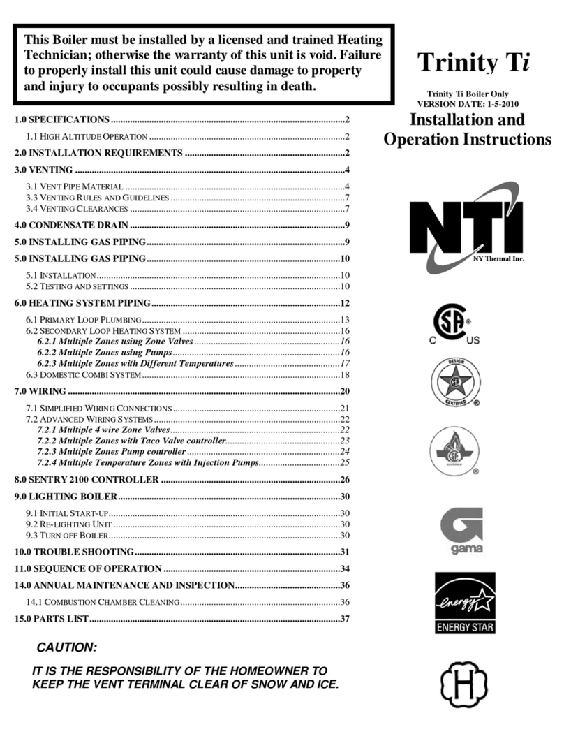
NTI TFTN285 User manual


This manual suits for next models
2
Table of contents
Other NTI Boiler manuals

NTI
NTI Trinity Tft399 User manual

NTI
NTI Trinity Tft285 User manual
NTI
NTI Triton VS80-130 Owner's manual
NTI
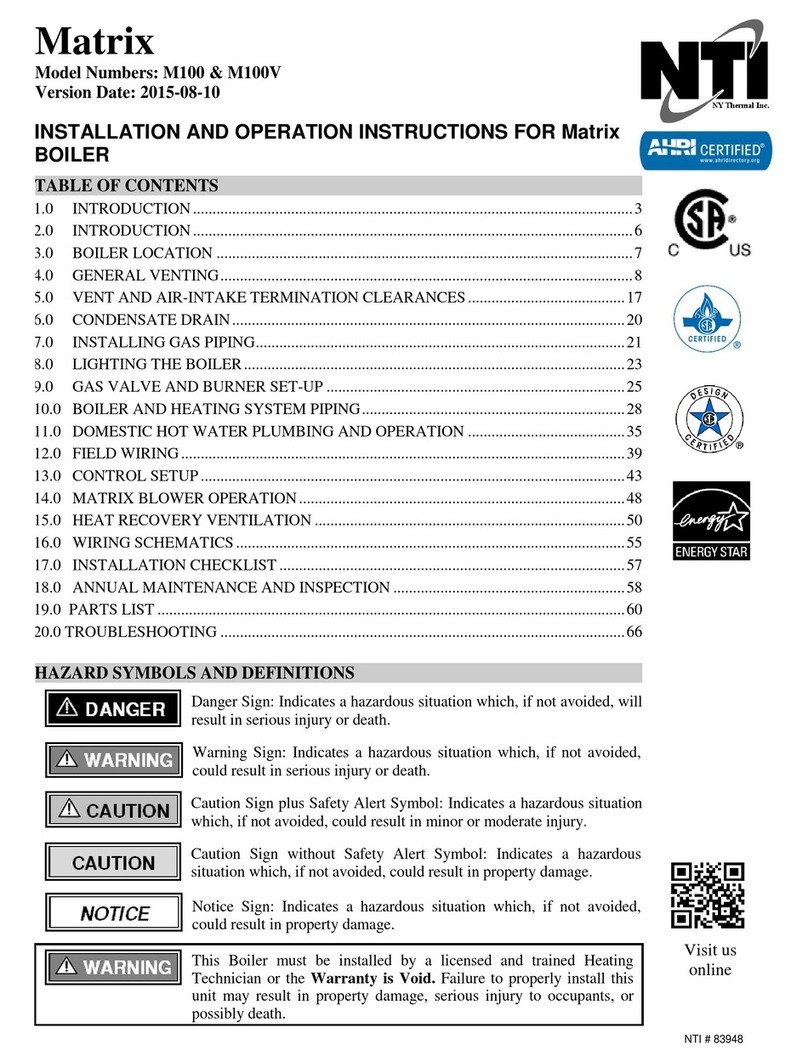
NTI Matrix User manual

NTI
NTI Trinity Lx 150 User manual

NTI
NTI TRX150 User manual
NTI
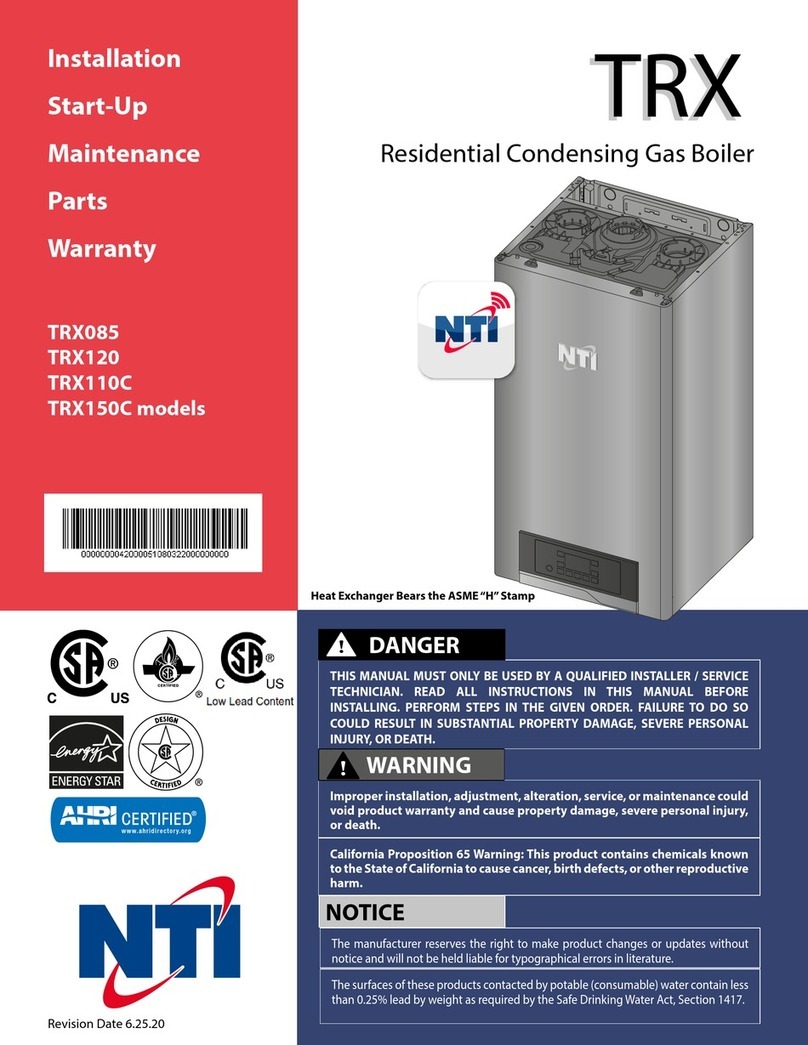
NTI TRX085 Installation manual
NTI
NTI TFTN500 User manual

NTI
NTI GF150 User manual

NTI
NTI TRX Series Installation manual
Popular Boiler manuals by other brands

Daikin
Daikin ESIE13-02 Service manual

Intergas
Intergas 18 OV Installation, service and user instructions

Wolf
Wolf CGU-2-18 Installation and maintenance instructions

Ferroli
Ferroli BLUEHELIX 25/32 K 50 Instructions for use, installation and maintenance

Viadrus
Viadrus HERCULES ECO Operation and installation manual

Main
Main Combi 30 HE Installation & service instructions

Immergas
Immergas MINI NIKE 3 E Technical manual

Alternate Heating
Alternate Heating wood gun E100 SF Installation and operator's guide

STOKVIS ENERGY SYSTEMS
STOKVIS ENERGY SYSTEMS R1 Series Planner Manual

Worcester
Worcester GREENSTAR 24i junior User instructions & customer care guide

Williamson-Thermoflo
Williamson-Thermoflo GWS-090E manual

VOKERA
VOKERA Linea Installation & servicing instructions

Electro Industries
Electro Industries EB-MO-10 Installation & operating instructions

Thermo Dynamics
Thermo Dynamics TDX-90 Installation and operating manual

STOKVIS ENERGY SYSTEMS
STOKVIS ENERGY SYSTEMS ECONOFLAME R40 Installation operation & maintenance

Energy Star
Energy Star ESC Installation operating and maintenance istructions
Glowworm
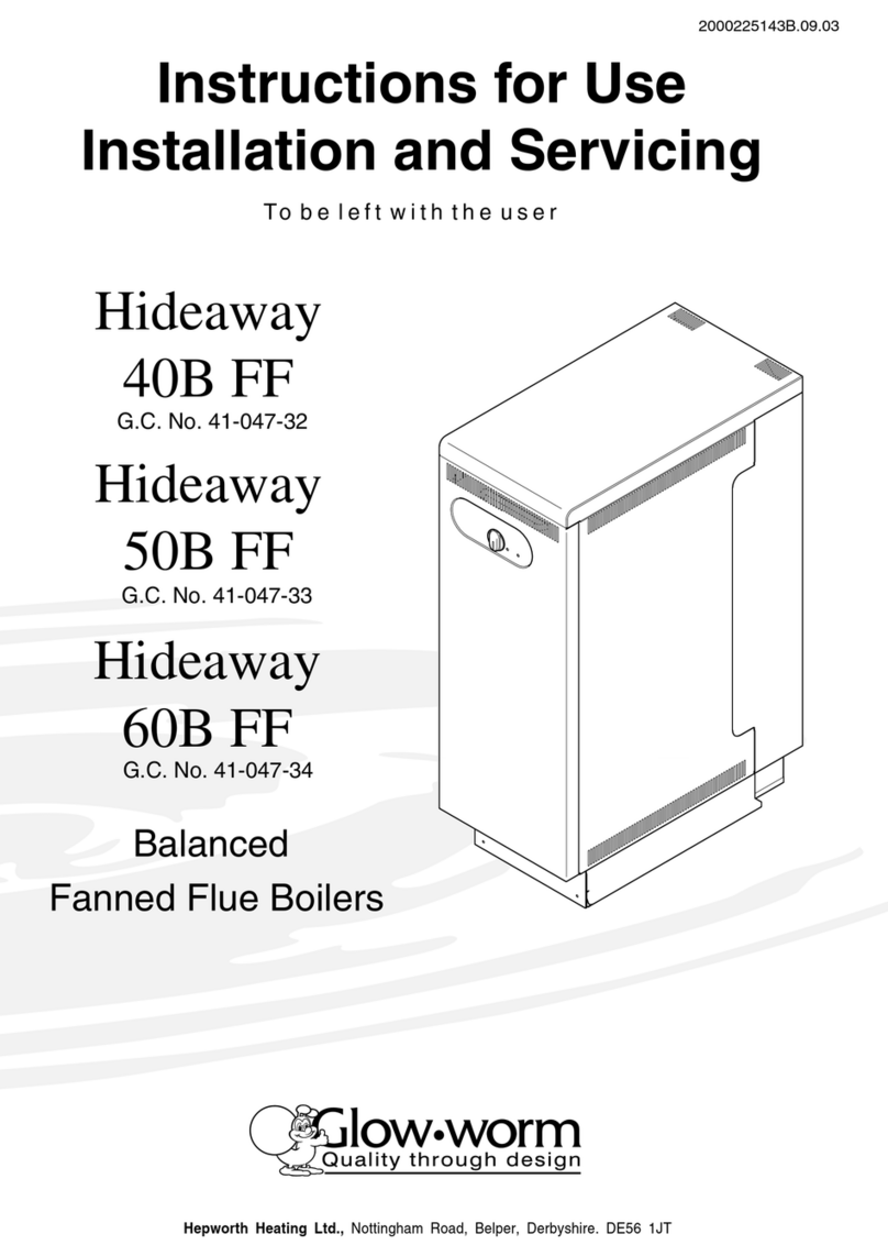
Glowworm Hideaway 50B FF Instructions for use installation and servicing
Glowworm
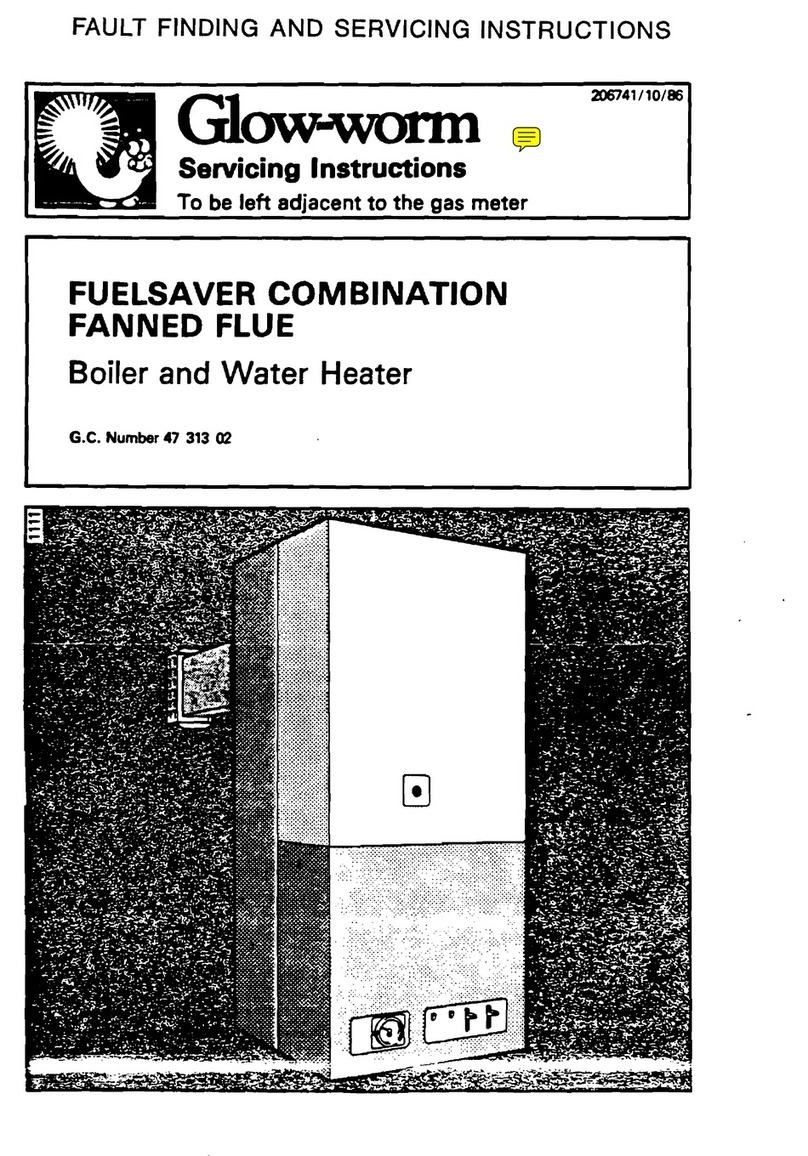
Glowworm fuelsaver Service manual
