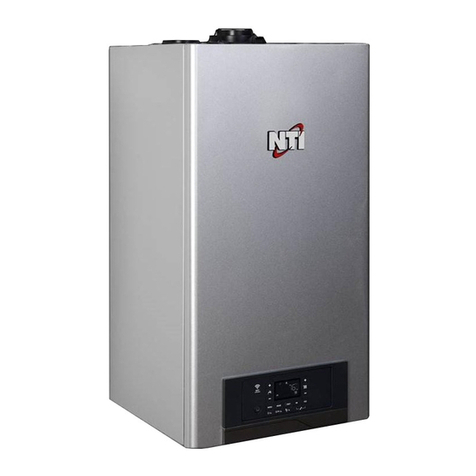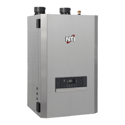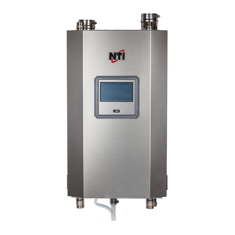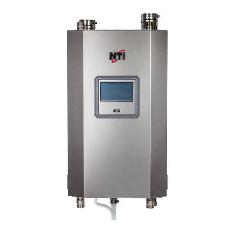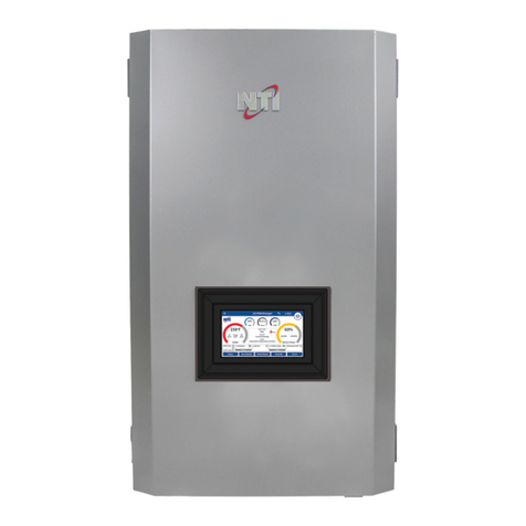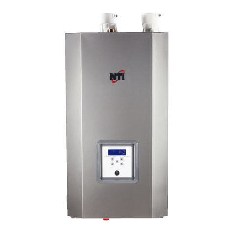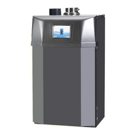
GF200
Quick Installation Guide
STEP 1 - BEFORE INSTALLING
Read both the GF200 and NPE-240A
Installation manuals before installing.
This product must be installed and serviced
by a licensed plumber, a licensed gas tter, or
a professional service technician. NTI is not
liable for any damages or defects resulting
from improper installation.
When applicable, the installation must conform with Manufactured
Home Construction and Safety Standards, Title 24 CFR, Part 3280
and/or CAN/CSA Z240 MH Series, Mobile Homes.
Safety
WARNING
Follow all local codes and/or the most recent edition of the National
Fuel Gas Code (ANSI Z223.1/NFPA 54) in the USA, or the Natural Gas
and Propane Installation Code in Canada (CAN/CGA B149.1).
GF 200
Installation Manual
Clearances[Dégagements]
GF200
COMBINATIONGASWATERHEATER/CENTRALAIRHEATING
*COMBINAISONCHAUFFEE-EAUINSTANTANE/GENERATEUR
D'AIRCHAUD
#####
MadeinCanada
FabriquesauCanada
SerialNumber:#####
####################
AIRFLOW
Thisapplianceisapprovedforupflowinstallation.
Cettefournaiseestapproveepourl'installationetcirculationd'airascendente.
Min.clearancetocombustibleconstruction:(in.)seediagram.
Degagementsminimumentrel'appareiletdesconstructionscombustibles(PO.)
Ventclearancetocombustibleconstruction(in.):0
Degagementdeventconstructionscombustibles(PO.):0
*Minserviceclearance
*Degagementmin.pourfinsd'entretienpourlesinstallations
C:COMBUSTIBLEFLOORS
RefertoInstallationManualforserviceclearancedetails
0
0
0
0
24*
C
ElectricalRating/CaracteristiqueElectrique
VOLTSFREQ.PHASEMCAMAX.CKT.BRKINDOORBLOWERMOTOR
12060Hz113A 9.6A3/4
FLAHP
Certifiedby
Certifiepar
NYThermalInc.30StonegateDr.,SaintJohn,NB,E2H0A4,Canada
Model
[Modele]
Fuel
[Gaz]
Altitude,ft
[Altitude,pi]
Input,MBH
[Entrée,kW]
MinMax
SpaceHeating
Capacity,MBH
[Capacitede
Chauffage,kW]
Nat.19.9[5.83]200[58.61]
0-4500*
TGF-200
LP
DHWHeating
Capacity,MBH
[CapacitedeDHW
Chauffage,kW]
80[23.45]200[58.61]
FACTORYSETFORNATURALGAS
FieldconvertedtoPropaneGas
CONFIGURÉEAL'USINEPOURGAZNATUREL
Convertieaupropanesurplace
Date:________________________________Date:________________________________
GasPressure[PressionduGaz]Natural[Naturel]Propane
MaximumInletGasPressure[Pressionmaximaled'entréedugaz]
MinimumInletGasPressure[Pressionminimumd'entréedugaz]
ManifoldPressure[Pressiond'admission]
10.5"WC
3.5"WC
-0.58"WC
13"WC
8"WC
-0.02/-0.78"WC
ImportantInformation[RensignesmentsImportants]
UseforNaturalorLPGasonly.
MaximumWaterPressure=150psi
MaximumStaticPressure=0.8IN.W.C.
MaximumInletWaterTemperature=180°F
Thisappliancemustbeinstalledinaccordance
withlocalcodes,ifany;ifnot,followANSI
Z223.1/NFPA54orCAN/CSAB149.1,Natural
GasandPropaneInstallationCode,as
applicable.
UtilisezdesgazNaturelouLPseulement.
Pressiond'eaumax.=150lb/po²
Pressionstatiquemax.=0.8PO.D'EAU
Temp.maximaled'eaud'entrée=180°F
Cetappareildoitêtreinstalléconformémentauxcodes
locaux,lecaséchéant;sinon,suivezANSIZ223.1/
NFPA54ouCAN/CSAB149.1,gaznaturelet
propaneCoded'installation,lecaséchéant.
FORYOURSAFETY
Donotstoreorusegasolineorother
flammablevaporsandliquidsinthevicinity
ofthisoranyotherappliance.
POURVOTRESÉCURITÉ
Nepasentreposerouutiliserd'essenceoud'autres
vapeursetliquidesinflammablesàproximitédecet
appareiloudetoutautreappareil.
StandardANSIZ21.10.3/CSA4.3
GasWaterHeaters,VolumeIIIStorageWater
Heaters,withInputRatingsAbove75,000BTU
perHour,CirculatingandInstantaneous
CSAC22.2No.236/UL1995
HeatingandCoolingEquipment
*Refertowaterheaterratingplateunderaccesspanelontheoppositesideofthiscabinet.
OrificesnecessaryforLPconversionareprovided.
Failuretousethecorrectgascancauseproblems
whichcanresultindeath,seriousinjuryorproperty
damage
LesinjecturesnecessairesalaconversionauGPLsont
fournis.
Lefaitdenepasutiliserlebongazpeutcauserdes
problemesquipeuventmeneralamort,causerdesbessures
gravesouendommagerlapropriete
24*
24*
Waterheaterratingplatelocatedunderaccesspanelonoppositesideofcabinet.
20A
DO NOT install in areas with excessively
high humidity or poor air quality (dust,
particulate matter, etc.)
STEP 2 - INSTALLING
1Unpacking
GF200
InstallationManual
Clearances[Dégagements]
GF200
COMBINATIONGASWATERHEATER/CENTRALAIRHEATING
*COMBINAISONCHAUFFEE-EAUINSTANTANE/GENERATEUR
D'AIRCHAUD
#####
MadeinCanada
FabriquesauCanada
SerialNumber:#####
####################
AIRFLOW
Thisapplianceisapprovedforupflowinstallation.
Cettefournaiseestapproveepourl'installationetcirculationd'airascendente.
Min.clearancetocombustibleconstruction:(in.)seediagram.
Degagementsminimumentrel'appareiletdesconstructionscombustibles(PO.)
Ventclearancetocombustibleconstruction(in.):0
Degagementdeventconstructionscombustibles(PO.):0
*Minserviceclearance
*Degagementmin.pourfinsd'entretienpourlesinstallations
C:COMBUSTIBLEFLOORS
RefertoInstallationManualforserviceclearancedetails
0
0
0
0
24*
C
ElectricalRating/CaracteristiqueElectrique
VOLTSFREQ.PHASEMCAMAX.CKT.BRKINDOORBLOWERMOTOR
12060Hz113A9.6A3/4
FLAHP
Certifiedby
Certifiepar
NYThermalInc.30StonegateDr.,SaintJohn,NB,E2H0A4,Canada
Model
[Modele]
Fuel
[Gaz]
Altitude,ft
[Altitude,pi]
Input,MBH
[Entrée,kW]
MinMax
SpaceHeating
Capacity,MBH
[Capacitede
Chauffage,kW]
Nat.19.9[5.83]200[58.61]
0-4500*
TGF-200
LP
DHWHeating
Capacity,MBH
[CapacitedeDHW
Chauffage,kW]
80[23.45]200[58.61]
FACTORYSETFORNATURALGAS
FieldconvertedtoPropaneGas
CONFIGURÉEAL'USINEPOURGAZNATUREL
Convertieaupropanesurplace
Date:________________________________Date:________________________________
GasPressure[PressionduGaz]Natural[Naturel]Propane
MaximumInletGasPressure[Pressionmaximaled'entréedugaz]
MinimumInletGasPressure[Pressionminimumd'entréedugaz]
ManifoldPressure[Pressiond'admission]
10.5"WC
3.5"WC
-0.58"WC
13"WC
8"WC
-0.02/-0.78"WC
ImportantInformation[RensignesmentsImportants]
UseforNaturalorLPGasonly.
MaximumWaterPressure=150psi
MaximumStaticPressure=0.8IN.W.C.
MaximumInletWaterTemperature=180°F
Thisappliancemustbeinstalledinaccordance
withlocalcodes,ifany;ifnot,followANSI
Z223.1/NFPA54orCAN/CSAB149.1,Natural
GasandPropaneInstallationCode,as
applicable.
UtilisezdesgazNaturelouLPseulement.
Pressiond'eaumax.=150lb/po²
Pressionstatiquemax.=0.8PO.D'EAU
Temp.maximaled'eaud'entrée=180°F
Cetappareildoitêtreinstalléconformémentauxcodes
locaux,lecaséchéant;sinon,suivezANSIZ223.1/
NFPA54ouCAN/CSAB149.1,gaznaturelet
propaneCoded'installation,lecaséchéant.
FORYOURSAFETY
Donotstoreorusegasolineorother
flammablevaporsandliquidsinthevicinity
ofthisoranyotherappliance.
POURVOTRESÉCURITÉ
Nepasentreposerouutiliserd'essenceoud'autres
vapeursetliquidesinflammablesàproximitédecet
appareiloudetoutautreappareil.
StandardANSIZ21.10.3/CSA4.3
GasWaterHeaters,VolumeIIIStorageWater
Heaters,withInputRatingsAbove75,000BTU
perHour,CirculatingandInstantaneous
CSAC22.2No.236/UL1995
HeatingandCoolingEquipment
*Refertowaterheaterratingplateunderaccesspanelontheoppositesideofthiscabinet.
OrificesnecessaryforLPconversionareprovided.
Failuretousethecorrectgascancauseproblems
whichcanresultindeath,seriousinjuryorproperty
damage
LesinjecturesnecessairesalaconversionauGPLsont
fournis.
Lefaitdenepasutiliserlebongazpeutcauserdes
problemesquipeuventmeneralamort,causerdesbessures
gravesouendommagerlapropriete
24*
24*
Waterheaterratingplatelocatedunderaccesspanelonoppositesideofcabinet.
20A
GF200
Manual Packet
LP Conversion Kit
Spare Parts Kit
Installation Kit Box
When you unpack the GF200, you will nd
the following items inside the appliance. Check
for each of the following items before installing
the appliance.
1
2Location Requirements
Install the appliance in an area that allows for service and maintenance access
to utility connections, piping, ductwork, lters, and traps. Based on the installa-
tion location, ensure the following clearances are maintained:
Minimum clearance: Clearance to
combustibles
Recommended
service clearances
Top 9 in as required
Back
Front * (or as required)*
Side (w/o connections) as required
Side (w/ connections) as required
Side (Blower access) 24 in
Bottom
When locating the appliance prior to completing the ductwork and plumbing,
it is essential that sucient space be allotted for the installation and mainten-
ance of components such as:
• Flow switch
• Thermostatic Mixing Valve (TMV)
• Pressure Relief Valve (PRV)
• Shut o and drain valves
• Expansion tank (optional)
• Condensate drain (and optional pump)
• Return air lter
• Circulating blower
* No clearance required to front of unit if obstruction is removable (such as a door or access panel). 24
inch clearance if obstruction is permanent.
3Checking the Rating Plate
Clearances[Dégagements]
IFW-80-200
COMBINATIONGASWATERHEATER/CENTRALAIRHEATING
*COMBINAISONCHAUFFEE-EAUINSTANTANE/GENERATEUR
D'AIRCHAUD
#####
MadeinCanada
FabriquesauCanada
SerialNumber:#####
########## ##### #####
AIRFLOW
Thisapplianceisapprovedforupflowinstallation.
Cettefournaiseestapproveepourl'installationetcirculationd'airascendente.
Min.clearancetocombustibleconstruction:(in.)seediagram.
Degagementsminimumentrel'appareiletdesconstructionscombustibles(PO.)
Ventclearancetocombustibleconstruction(in.):0
Degagementdeventconstructionscombustibles(PO.):0
*Minserviceclearance
*Degagementmin.pourfinsd'entretienpourlesinstallations
C:COMBUSTIBLEFLOORS
RefertoInstallationManualforserviceclearancedetails
0
0
0
0
24*
C
ElectricalRating/CaracteristiqueElectrique
VOLTSFREQ. PHASEMCAMAX.CKT.BRK INDOORBLOWERMOTOR
12060Hz 113A 9.6A 3/4
FLA HP
Certifiedby
Certifiepar
NYThermalInc.30StonegateDr.,SaintJohn,NB,E2H0A4,Canada
Model
[Modele]
Fuel
[Gaz]
Altitude,ft
[Altitude,pi]
Input,MBH
[Entrée,kW]
MinMax
SpaceHeating
Capacity,MBH
[Capacitede
Chauffage,kW]
Nat. 19.9[5.83]200[58.61]
0-4500*
IFW-80-200
LP
DHWHeating
Capacity,MBH
[CapacitedeDHW
Chauffage,kW]
80[23.45] 200[58.61]
FACTORYSETFORNATURALGAS
FieldconvertedtoPropaneGas
CONFIGURÉEAL'USINEPOURGAZNATUREL
Convertieaupropanesurplace
Date:________________________________Date:________________________________
GasPressure[PressionduGaz] Natural[Naturel]Propane
MaximumInletGasPressure[Pressionmaximaled'entréedugaz]
MinimumInletGasPressure[Pressionminimumd'entréedugaz]
ManifoldPressure[Pressiond'admission]
10.5"WC
3.5"WC
-0.58"WC
13"WC
8"WC
-0.02/-0.78"WC
ImportantInformation[RensignesmentsImportants]
UseforNaturalorLPGasonly.
MaximumWaterPressure=150psi
MaximumStaticPressure=0.8IN.W.C.
MaximumInletWaterTemperature=180°F
Thisappliancemustbeinstalledinaccordance
withlocalcodes,ifany;ifnot,followANSI
Z223.1/NFPA54orCAN/CSAB149.1,Natural
GasandPropaneInstallationCode,as
applicable.
UtilisezdesgazNaturelouLPseulement.
Pressiond'eaumax.=150lb/po²
Pressionstatiquemax.=0.8PO.D'EAU
Temp.maximaled'eaud'entrée=180°F
Cetappareildoitêtreinstalléconformémentauxcodes
locaux,lecaséchéant;sinon,suivezANSIZ223.1/
NFPA54ouCAN/CSAB149.1,gaznaturelet
propaneCoded'installation,lecaséchéant.
FORYOURSAFETY
Donotstoreorusegasolineorother
flammablevaporsandliquidsinthevicinity
ofthisoranyotherappliance.
POURVOTRESÉCURITÉ
Nepasentreposerouutiliserd'essenceoud'autres
vapeursetliquidesinflammablesàproximitédecet
appareiloudetoutautreappareil.
StandardANSIZ21.10.3/CSA4.3
GasWaterHeaters,VolumeIIIStorageWater
Heaters,withInputRatingsAbove75,000BTU
perHour,CirculatingandInstantaneous
CSAC22.2No.236/UL1995
HeatingandCoolingEquipment
*Refertowaterheaterratingplateunderaccesspanelontheoppositesideofthiscabinet.
OrificesnecessaryforLPconversionareprovided.
Failuretousethecorrectgascancauseproblems
whichcanresultindeath,seriousinjuryorproperty
damage
LesinjecturesnecessairesalaconversionauGPLsont
fournis.
Lefaitdenepasutiliserlebongazpeutcauserdes
problemesquipeuventmeneralamort,causerdesbessures
gravesouendommagerlapropriete
24*
24*
Waterheaterratingplatelocatedunderaccesspanelonoppositesideofcabinet.
20A
RatingPlate, *Plaque Signalétique
DirectVentAutomaticInstantaneous Water Heater *Chauffe-eau instantané automatique à évent direct
ForIndoor,Outdooror Manufactured Home (Mobile Home) Installation *Pour installation dans une maison préfabriquée (mobile)
Navien,Inc.
20Goodyear,Irvine, CA 92618
Tel:1-800-519-8794
Orificesnecessaryfor LP conversion are provided. *Les injectures nécessaires à la conversion au GPL sont fournis.
Failuretouse the correct gas can cause problems which can result in death, serious injury or property damage. *Le fait de ne pas
utiliserlebon gaz peut causer des problèmes qui peuvent mener à la mort, causer des blessures graves ou endommager la propriété.
Consultyourinstallation manual for more information. *Consultez votre manuel d’installation pour plus d’information.
Suitableforcombination water (potable) heating and space heating and not suitable for space heating applications only.
*Convientauchauffage combiné de l’eau (potable) et des locaux, mais non au chauffage des locaux seulement.
Thisapplianceis certified for use at altitudes up to 4,500 ft (1,370 m) in accordance to the latest CAN/CGA 2.17-High Altitude Installation
proceduresatnormal manifold pressure. For installation instructions at altitudes higher than 4,500 ft, please contact Navien. *Cet appareil
estcertifiépour une utilisation à des altitudes de 0 à 4,500 pieds (1,370 m) conformément aux toutes les procédures d’installation à haute
altitudeCAN/CGA2.17 à une pression normale. Pour les installations à élévations en haut de 4,500 pieds, appeler le bureau de Navien.
Thisappliancemust be installed in accordance with local codes, or in the absence of local codes, the National Fuel Gas Code, ANSI
Z223.1/NFPA54or the CSA B149.1, Natural Gas and Propane Installation Code. *Cet appareil doit être installé selon les règlements
locaux,ouen l’absence de tels règlements, selon le National Fuel Gas Code, ANSI Z223.1/NFPA 54, ou les, Code d'installation du gaz
naturaletdu propane, CSA-B149.1.
ModelNo.,*Numéro de modèle
NPE-210A
Max.InputRating, *Entrée GPL max.
180,000Btu/h
RecoveryRating,*Calibre de recouvrement
Max.InletGas Pressure, *Pression max. de gaz d’entrée
Min.InletGas Pressure, *Pression min. de gaz d’entrée
ManifoldPressure,*Pression d’admission
ElectricalRating,*Régime nominal électrique
Max.WaterPressure, *Pression d’eau max.
TypeofGas, *Type de gaz
NG
Min.InputRating, *Débit calorifique max.
19,900Btu/h
265Gallons/Hour,*gallons/heures
10.5InchesW.C. *pouces W.C.
3.5InchesW.C. *pouces W.C.
-0.36InchesW.C. *pouces W.C.
AC*c.a.120 Volts 60Hz, less than 2 amperes, *Utilise moins de 2A
150psi*lb/po2 ANSI Z21.10.3 · CSA 4.3-2011
FORYOURSAFETY *POUR VOTRE SÉCURITÉ
Donotstore or use gasoline or other flammable vapors and liquids in the vicinity of this or any other gas appliances. *Ne rangez
pasetn'utilisez pas d'essence ou d'autres liquides ou vapeurs inflammables près de cet appareil ou de tout autre appareil électroménager.
Clearances[Dégagements]
GF 200
COMBINATIONGASWATER HEATER / CENTRAL AIR HEATING
COMBINAISONCHAUFFEE-EAUINSTANTANE / GENERATEUR
D'AIRCHAUD
#####
MadeinCanada
FabriquesauCanada
SerialNumber: #####
##### ##### ##### #####
AIRFLOW
Thisapplianceis approved for upflow installation.
Cette fournaise est approvée pour l'installation et circulation d'air ascendente.
Min.clearanceto combustible construction: (in.) see diagram.
Dégagements minimum entre l'appareil et des constructions combustibles (PO.)
Ventclearanceto combustible construction (in.): 0
Dégagement de vent constructions combustibles (PO.): 0
*Minservice clearance
* Dégagement min. pour fins d'entretien pour les installations
C: COMBUSTIBLE FLOORS
*Refer to Installation Manual for service clearance details
0
0
0
0
24*
C
ElectricalRating/ Caractéristique Électrique
VOLTS INDOORBLOWERMOTOR
120 60Hz 1 12A 9.6A 3/4
RATEDAMPS HP
Certifiedby
Certifiepar
NYThermalInc. 30 Stonegate Dr., Saint John, NB, E2H 0A4, Canada
Model
[Modèle]
Fuel
[Gaz]
Altitude,ft
[Altitude,pi]
Input,MBH
[Entrée,kW]
Min Max
SpaceHeating
Capacity,MBH
[Capacitéde
Chauffage,kW]
Nat. 19.9[5.83] 200[58.6]
0-4500*
GF200
LP
80[23.5]
FACTORYSETFOR NATURAL GAS
Fieldconvertedto Propane Gas
CONFIGURÉEÀL'USINE POUR GAZ NATUREL
Convertieaupropane sur place
Date:________________________________ Date:________________________________
GasPressure[Pression du Gaz] Natural[Naturel] Propane
MaximumInletGas Pressure [Pression maximale d'entrée du gaz]
MinimumInletGas Pressure [Pression minimum d'entrée du gaz]
ManifoldPressure[Pression d'admission]
10.5"WC
3.5"WC
-0.58"WC
13"WC
8"WC
-0.02/-0.78" WC
ImportantInformation[Rensignesments Importants]
UseforNatural or LP Gas only.
MaximumWaterPressure = 150 psi
MaximumStaticPressure = 0.8 IN. W.C.
MaximumInletWater Temperature = 180°F
Thisappliancemust be installed in accordance
withlocalcodes, if any; if not, follow ANSI
Z223.1/NFPA54or CAN/CSA B149.1, Natural
GasandPropane Installation Code, as
applicable.
Utilisezdesgaz Naturel ou LP seulement.
Pressiond'eaumax. = 150 lb/po²
Pressionstatiquemax. = 0.8 PO. D'EAU
Temp.maximaled'eau d'entrée = 180°F
Cetappareildoit être installé conformément aux codes
locaux,lecas échéant ; sinon, suivez ANSI Z223.1 /
NFPA54ou CAN / CSA B149.1, gaz naturel et
propaneCoded'installation, le cas échéant.
FORYOURSAFETY
Donotstore or use gasoline or other
flammablevaporsand liquids in the vicinity
ofthisor any other appliance.
POURVOTRESÉCURITÉ
Nepasentreposer ou utiliser d'essence ou d'autres
vapeursetliquides inflammables à proximité de cet
appareiloude tout autre appareil.
StandardANSIZ21.10.3 / CSA 4.3
GasWaterHeaters, Volume III Storage Water
Heaters,withInput Ratings Above 75,000 BTU
perHour,Circulating and Instantaneous
CSAC22.2No. 236 / UL 1995
HeatingandCooling Equipment
*Referto water heater rating plate on the opposite side of this cabinet.
Orificesnecessaryfor LP conversion are provided.
Failuretouse the correct gas can cause problems
which can result in death, serious injury or property
damage.
Lesinjecturesnécessaires à la conversion au GPL sont
fournis.
Lefaitde ne pas utiliser le bon gaz peut causer des
problèmesquipeuvent mener à la mort, causer des blessures
gravesouendommager la propriété.
24*
24*
Waterheaterrating plate located on opposite side of cabinet.
20A
FREQ. PHASE MCA MAX. CKT. BRK.RATEDAMPS
15A
Part#85477
The GF200 is congured for
Natural Gas from the factory.
If conversion to Propane Gas
is required, the conversion kit
supplied with the water heater
must be used.
• Before connecting the gas supply, determine the gas type and pressure
for the water heater by referring to the rating plate. Use only the same
gas type indicated on the rating plate. Using a dierent gas type will
result in abnormal combustion and malfunction of the water heater.
Gas supplies should be connected by a licensed professional only.
• The appliance and its gas connection must be leak tested before
placing the appliance in operation.
• The water heater cannot be converted from natural gas to propane or
vice versa without the supplied gas conversion kit. Do not attempt a
eld conversion of the water heater without a the gas conversion kit.
Doing so will result in dangerous operating conditions and will void the
warranty.
NTI is not liable for any property damage and/or personal injury resulting
from improper conversions.
WARNING
4Return Air Ducting
The return air may be delivered to the
appliance via:
a) either side;
b) the back;
c) the bottom; or
d) any combination thereof, provided, in
all cases, that access to at least one side
door remains clear (24”min.) for blower
access and maintenance.
MAX CUTTING
BOUNDARY
18” x 18”
(324 sq. in.)
MAX
CUTTING
BOUNDARY
14.5” x 24.5”
(355 sq. in.)
Side Back Bottom
In all installations, an appropriate air ltration system is recommended and
must meet test requirements in UL 900. Failure to install and properly main-
tain such a system could lead to damage to and/or premature failure of the
space heating components.
In all cases, care must be taken to ensure that return ducting is sealed against
the inlet, such that the entire air steam is directed through the air lter. Failure
to do so could cause damage to the air moving equipment and clogging of
the heating and/or cooling coils.
NOTE: For details and recommendations on side, back or bottom return ducting see
GF200 Installation Manual.
5Venting
Max length: 150’ Max length: 60’
12
8
Max number of
elbows: 8
Max number of
elbows: 6
12
6
3”Venting
1 in (25 mm) min.
Combustion Air
Vent
Maintain 12” min. clearance above
highest anticipated snow level or grade.
Combustion Air
Combustion Air
Vent
Maintain 12” min. (18” min. for Canada)
clearance above highest anticipated
snow level.
Max. 24” above roof.
Vent
Combustion Air
2”Venting
Vent Termination Options
Concentric Vent Terminations
12 in (300 mm) min.
12 in (300 mm) min.
36 in (900 mm) min.
Horizontal Vent Termination
Interior View
Exterior View
Vertical Vent Termination
12” Min
from any
obstruction
above, below,
left or right.
Exhaust Vent Materials
From factory, the GF200 operates at water temperatures exceeding 150°F,
resulting in the potential for exhaust temperatures to exceed 149°F.
As such, high-temperature vent pipe material (CPVC or polypropylene; see table
below) must be used for the rst 3 feet (2" venting) or 0.5 feet (3" venting).
If such materials are unavailable, see the Venting section of the GF200 manual for
instructions on how to limit the maximum water temperature set point.
* Approved polypropylene systems include: Duravent Polypro (Single Wall): 2PPS-
xxx (2in), 3PPS-xxx (3 in) / Centrotherm Innoue SW: ISxx02xx (2 in), ISxx03xx (3 in)
/ Centrotherm InnoFlue Flex: IFVL02XXX (2 in). Refer to the manufacturer’s litera-
ture for detailed information.
** For installation in Canada, eld-supplied plastic vent piping must comply
with CAN/CGA B149.1 (latest edition) and be certied to the Standard. For Type
BH Gas Venting Systems, ULC-S636. Components of this listed system must not
be interchanged with other vent systems or unlisted pipes or ttings. All plastic
components and specied primers and glues of the certied vent system must
be from a single system manufacturer and must not be intermixed with another
system manufacturer’s parts. The supplied vent connector and vent termination
are certied as part of the water heater.
2
Locale Recommended Vent Materials
USA
Canada**
• PVC Schedule 40 (Solid core)
• CPVC Schedule 40 or 80 (Solid core)
• Approved Polypropylene*
• Type BH Special Gas Vent Class IIA (PVC)
• Type BH Special Gas Vent Class IIB (CPVC)
• Type BH Special Gas Class IIC (Polypropylene)
33
NOTE:
The service clearances are
recommendations.
If you are unable to
maintain those specic
clearances, be sure you
have an alternative plan
as to how you are going to
service the unit.
Intake
Exhaust
12 in (300 mm) min.
12 in (300 mm) min.
12 in (300 mm) min.
Intake
Exhaust
Exhaust
Intake
15.5” x 20”
(310 sq. in.)
Vent
Venting requirements dier in the US and Canada. Consult the following chart
or the most recent edition of ANSI Z223.1/NFPA 54 or CAN/CGA B149.1, as
well as all applicable local codes and regulations when selecting vent pipe
materials. Do not use cellular core PVC (ASTM F891), cellular core CPVC, or Radel®
(polyphenolsulfone) for the exhaust vent.
90° = 5 linear feet
45° = 3 linear feet
90° = 8 linear feet
45° = 4 linear feet
Located on interior left side
of cabinet (near buer tank).
Located on interior right side of
cabinet (near heat exchanger).
See sub-step: 6Plumbing
