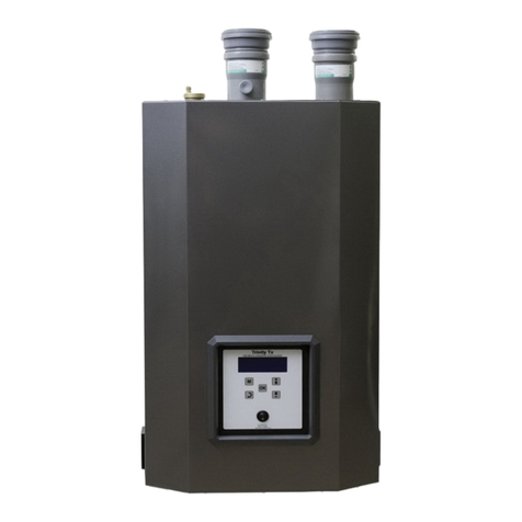
Lx Series Installation and Operation Instructions
│Trinity Lx
7
3.0 APPLIANCE LOCATION
In all cases, the Trinity Lx must be installed indoors in a dry location where the ambient temperature must be
maintained above freezing and below 100°F [38°C]. Gas components must be protected from dripping, spraying
water, or rain during operation and servicing. Consider the proximity of system piping, gas and electrical supply,
condensate disposal drain, and proximity to vent termination when determining the best appliance location.
Water or flood damaged components must be replaced immediately with new factory-
approved components as failure to do so may result in fire, serious injury, or death.
Floor Mounting
The Trinity Lx can be mounted directly on combustible flooring, with the exception of carpeting. Installing the
appliance on carpeting is not permissible. Ensure the appliance is mounted above any anticipated flood level.
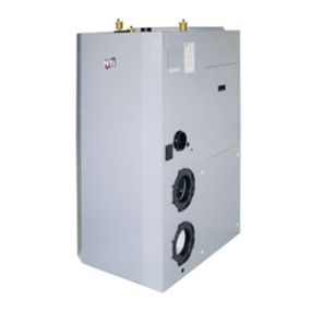
Models Lx150-400 come equipped with stationary, low profile legs. The Lx800 has factory supplied/field
installed leveling legs. Once the unit is removed from the pallet, thread the leveling legs into the allocated
threaded inserts in the bottom of the unit.
Appliance Area Ventilation Air Openings
If appliance area clearances are less then the recommended clearances specified in Table 3-1, the appliance area
must be ventilated. Each ventilation air opening must meet the minimum requirements of 1 in
2
per 1000 Btu/hr,
but not less then 100 in
2
. The lower ventilation opening must be located within 6” of the floor while the upper
opening must be located 6” from the top of the space. The Lx800 has an optional Indoor Combustion Air Kit
that can be installed in lieu of direct vent air intake piping. Note that the Indoor Combustion Air option is not to
be used in conjunction with closet or alcove installations. See "Mechanical Room Installations" below.
If the "Appliance Area" does not meet all of the recommended clearances listed in Table
3-1, it is considered a Closet or Alcove. In US
/
Canada, closet and alcove installations
require approved CPVC vent pipe, fittings, cements, and primers. See Table 4-3 for a list of approved materials.
Closet Installations
For closet installations, it is necessary to provide two ventilation air openings as shown in Figure 3-1(a), (b) and
(c), each providing a minimum area equal to 1 in
2
per 1000 Btu/hr, but not less then 100 in
2
and within 6” of the
top and bottom of the closet door. See Table 3-1for minimum recommended clearances.
Alcove Installations
Alcove installations have the same minimum clearances as closet installations, except the front must be
completely open to the room at a distance no greater then 18” [457 mm] from the front of the appliance and the
room is at least three (3) times the size of the alcove. Provided these conditions are met, the appliance requires
no extra ventilation air openings to the space. See Table 3-1for minimum recommended clearances.
Residential Garage Installations
When installed in a residential garage, mount the appliance a minimum of 18” [457 mm] above the floor. Locate
or protect the appliance so it cannot be damaged by a moving vehicle. Check with your local authorities for
other possible regulations pertaining to the installation of an appliance in a garage.
Mechanical Room Installations (Commercial)
The Trinity Lx800 is certified for use as a Direct Vent System, where flue gas and combustion air piping are
connected directly to the appliance. In addition, it is the only Lx model certified for use with an Indoor
Combustion Air System where flue gas piping is connected directly to the appliance, but combustion air is
drawn directly from the room. Room supplied combustion air systems are subject to additional codes
requirements such as pre-ignition interlocks with motorized dampers or auxiliary proving circuits when
operating in rooms with mechanical exhaust fans. See Table 4-1 for combustion air contamination sources to
avoid, Table 4-5 for a list of design considerations and installation guidelines, and Figure 4-13 for Kit details.
Wall Mounting Installations (Optional)
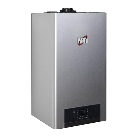
Lx150-400 models are shipped with wall mounting brackets to provide installers with the option of wall
mounting the appliance. Lx800 is not available as a wall mountable unit. Refer to Figures 3-3(a) and 3-3(b) for
instructions and illustrations on wall mounting applicable models. Note that Water Heaters require "Mandatory
Wall Mounting Protection". Refer to Section 1.0 in Appendix C, "Water Heater Applications: Plumbing &
Wiring Instructions" for further details.


