3
6. With all other gas appliances in the application running, operate the burner to the maximum firing rate (See I/O
manual) and compare the observed line pressure with Table 2-1. The pressure will be lowest during the
maximum flow of gas.
7. Adjust the gas line pressure to ensure the parameters in Table 2-1 are attained under all conditions. If possible
adjust the line pressure to the "Nominal/Desired" value listed in Table 2-1 while the unit is operating at the
maximum modulation rate.
8. Continue observing the gas line pressure until the completion of a combustion analyses in case adjustments need
to be made.
9. Complete pressure testing, remove the ¼” tubing from the test port and then return the bleed screw of the Line
Pressure Test Port to the closed position.
The line pressure is a function of the gas supply and is affected solely by field provided
parameters such as line size and regulator settings. Under no circumstances can the boiler gas
valve influence or be used to adjust the gas line pressure.
Failure to close the bleed screw of the Line Pressure Test Port will cause a severe leakage of
gas, resulting in a fire or explosion causing property damage, serious injury or death.
Table 2-1 Line Pressure and Combustion Parameters
Line Pressure (inches wc)
*Note: Observe the combustion products with the burner operating at the maximum modulation rate.
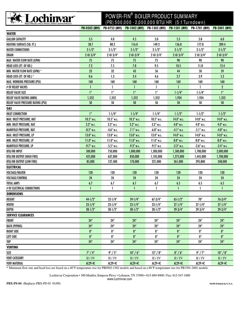
Table 2-2 Minimum and Maximum Input Ratings and Respective Modulation Rates
Min. Modulation Rate
(RPM)
Max. Modulation Rate
(RPM)
* Canada: Altitudes between 2000-4500 ft, de-rate by 10%. Consult local authorities for de-rating for altitudes above 4500ft.
Carbon Monoxide –DO NOT leave the unit operating if producing Carbon Monoxide (CO)
concentrations in excess of 175ppm. Failure to comply may result in serious injury or death.
Manifold Pressure - DO NOT adjust or measure the Manifold Pressure of the boiler. Correct
manifold pressure is factory set. Field adjustment could result in improper burner operation
resulting in fire, explosion, property damage or death.
Adjustment
Throttle / Input Screw Adjustments - The boiler is equipped with a Throttle/Input Adjustment Screw, located on the
Gas Valve. It is used to adjust the flow of gas leaving the gas valve entering the Venturi and then the combustion
air stream. Turn the adjustment screw in (clockwise) to reduce gas flow, make combustion leaner, and reduce the
CO2concentration in the flue gases. To increase the CO2level and gas flow in the combustion air stream, adjust
the Throttle screw out (counterclockwise). Typical adjustment for LP Gas is 0-1 turns in or out after having
performed the initial adjustment as per Section 1.0. See Figure 1-2 for throttle screw location.
Adjustments to the Throttle/Input-Screw may only be made by a qualified gas technician
while using a calibrated combustion analyzer capable of measuring CO2and CO.
Adjustments may only be performed if the gas line pressure is maintained above minimum
levels throughout the duration of the test, see Table 2-1. Failure to follow these instructions
may result in serious injury or death.
Throttle/Input Adjustment Screw
Increase gas
Turn Counter Clockwise
Decrease gas
Turn Clockwise


