Page 9
Model NG2 Revision 210798A
Check that the Low Gas Pressure switch is set to
minimum. Fit a manometer or other approved pres-
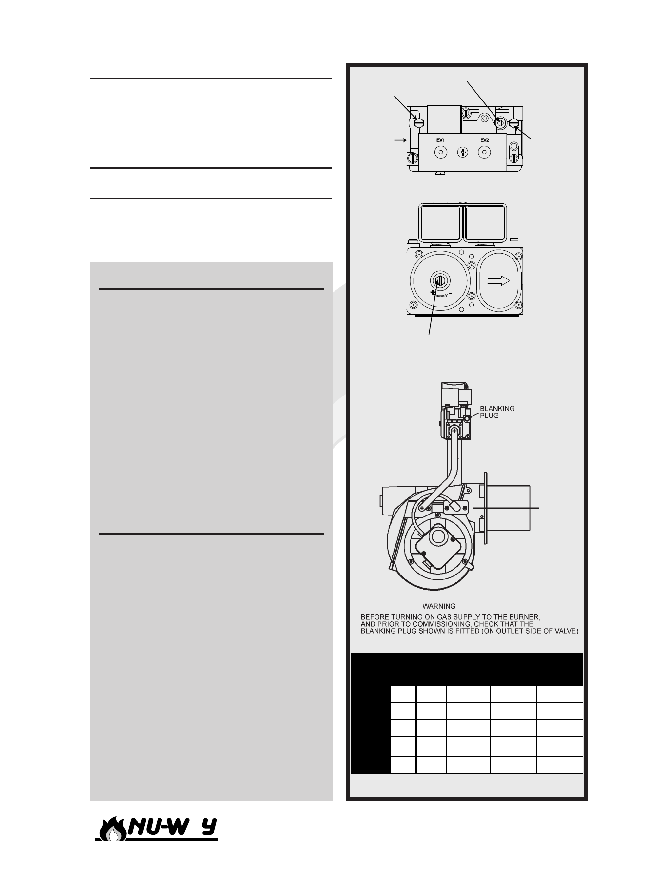
sure measuring instrument to the test point on the
downstream side of the gas valve. Open the up-
stream manual isolating valve approximately 15 to
20 deg and switch on the burner. With the fan
running, make a mental note of the pressure and
look for an increase in pressure during the ignition
stage. If no increase in pressure is detected then
increase the governor setting and restart the burner.
Note that it may be necessary to re-cycle the burner
a few times to purge air from the pipework. When
the flame is established, the flame relay is ener-
gised by the flame detection circuit and the burner
continues to run on main flame.
Make a quick visual check on the flame stability
and if it is O.K. then slowly open the manual gas
valve to the fully open position whilst checking for
excessive CO. Adjust the combustion air setting if
necessary to maintain the combustion figures within
acceptable limits.
Setting Main Flame Gas Rate
With the manometer still attatched, the main flame
gas rate can be set. Adjust the governed pressure
to that shown in the Gas Governor Settings table.
Check the gas flow rate at the meter. Ensure that
other appliances served by the same meter are iso-
lated when the flow tests are carrried out. Adjust-
ments to the governor setting can now be made to
obtain the required flow rate.
Combustion Air Settings
With the gas flow rate set and the burner running
with stable flame, the flue gases can be checked
for C02 and 02with suitable combustion testing in-
struments. Acceptable figures are given in the Al-
lowable Combustion Analysis table. For safety rea-
sons, the CO should not exceed 93 ppm. To
achieve good combustion efficiency, or if the CO
content is exceeded, adjustments to air and gas
can be made whilst the burner is on main flame.
To adjust the air flow, loosen the retaining screw
on the rotary air strap situated on the right hand
side of the burner. To increase the flow of air, turn
the air strap anti-clockwise as viewed from the right
hand side. To decrease combustion air flow, turn
the rotatry strap clockwise. Tighten the retaining
screw after each adjustment.
Setting The Step Start Facillity
The step start is used to reduce the gas rate during
the ignition period, therefore ensuring a smooth
quiet light up. Re-start the burner and note the
quality of ignition. If the light up is heavy, reduce
the amount of start rate gas by turning the adjust-
ing screw anti-clockwise. If the light up is weak,
then increase the amount of start rate gas by turn-
ing the adjusting screw clockwise. Repeat until a
satisfactory setting is achieved.
Important
After each adjustment, gas flow rate and flue gas
analysis should be re-checked.
Always
Use approved test equipment (Continually moni-
toring electronic equipment is recommended).
Never
Rely on a visual inspection of the flame as a guide
to combustion quality.
Air Pressure Switch Setting
Isolate the burner and remove the air pressure
switch cover. Switch on the electrical supply and
allow the burner to establish main flame. Slowly
turn the adjustment dial on the air pressure switch
clockwise until the flame is extinguished and the
burner locks out. Turn the dial one division anti-
clockwise and reset the burner control. The burner
will restart and continue its cycle to the main flame
condition or lock out. If the burner locks out re-
peat the adjustment procedure once per burner
cycle until main flame is established. Recheck the
performance and then turn the dial a further two
divisions anticlockwise. Switch off the burner and
replace the air pressure switch cover.
Low Gas Pressure Switch Setting
The low gas pressure switch is wired in series with
the appliance controlling instruments and will cause
the burner to effect a safety shut down if a loss of
inlet gas pressure is detected.
Gas Type %CO2 %O2
Min Max Min Max
Natural 99.5 3.5 5
L.P.G. 10.5 11 3.5 5
Allowable Combustion Analysis