NuAire Labgard NU-430-400 Manual

OM0228Page1of99
February/2014
LabgardESEnergySaverClassII,
TypeB2LaminarFlow
BiologicalSafetyCabinet
Models
NU‐430‐400/600
Bench/Console
Operation&MaintenanceManual
February,2014
(Series65)
Revision1
ManufacturedBy:
NuAire,Inc.
2100FernbrookLane
Plymouth,MN55447
Toll‐Free:1‐800‐328‐3352
InMinnesota:(763)‐553‐1270
Fax:(763)‐553‐0459

OM0228Page2of99
February/2014
Congratulations!
YouhavejustpurchasedoneofthefinestLaminarFlowBiologicalSafetyCabinetsavailable.Withpropercare,
maintenance(certification),andlaboratoryprocedure,thiscabinetwillgiveyouyearsofproductandpersonnelprotectionfrom
particulatecontaminantsasprescribedinNSF/ANSI49.Pleasereadthismanualcarefullytofamiliarizeyouwithproperinstallation,
maintenanceandoperationofthecabinet.Otherreferenceandguidelinematerialsareavailablethroughthefollowingwebsites.
www.hc‐sc.gc.ca
www.cdc.gov/od/ohs/
www.absa.org
www.absa‐canada.org
www.ebsa.be
www.inspection.gc.ca
www.who.int
www.biosafety.be
www.hse.gov.uk
www.nsf.org
www.cetainternational.org
www.osha.gov/dts/osta/
www.nuaire.com

OM0228Page3of99
February/2014
ABOUTTHISOPERATION&MAINTENANCEMANUAL
Theinformationcontainedinthismanualisintendedtoreflectourcurrentproductionstandardconfigurationmodelalong
withthemorefrequentlypurchasedoptions.Anyuniqueadditions/modifications/shopdrawingsareappendedinthebackflapof
thismanual,alongwithanymodificationsand/oradditionstoproceduresasoutlinedinthismanual.Acopyoftheoriginalfactory
testreportisalsoappendedtothismanual.Incasethismanualand/ortestreportislostormisplaced,NuAireretainsacopyinour
files.AreplacementcopycanbeobtainedbycallingorwritingNuAire,Inc.statingthemodelnumberandserialnumberandabrief
descriptionoftheinformationdesired.

OM0228Page4of99
February/2014
LabgardESEnergySaverClassII,TypeB2LaminarFlowBiologicalSafetyCabinet
ModelsNU‐430‐400/600Operation&MaintenanceManual
TABLEOFCONTENTS
SectionNo.1...........................................................GeneralInformation
SectionNo.2...........................................................Models&Features
SectionNo.3...........................................................Warranty
SectionNo.4...........................................................Shipments
SectionNo.5...........................................................InstallationInstructions
5.1.................................................................Location
5.2.................................................................Set‐upInstructions
5.3.................................................................Exhaust/SupplyAirChecks
5.4.................................................................CertificationTestingMethodsandEquipment
SectionNo.6...........................................................OperatingtheNU‐430
6.1.................................................................BiologicalSafetyCabinetControl
6.2.................................................................OperatingGuidelines
6.3.................................................................OperatingSequence
6.4.................................................................Ergonomics
6.5.................................................................CleaningProcedures
6.6.................................................................HazardousDrugDecontaminationProcedure
SectionNo.7...........................................................GeneralMaintenance
7.1.................................................................Decontamination
7.2.................................................................FluorescentLampBulbReplacement
7.3.................................................................HEPAFilter/MotorReplacement
7.4.................................................................SlidingWindowReplacement&Adjustment
7.5.................................................................AirflowControlSystemSetup&Calibration
7.6.................................................................HEPAFilterLeakTest
7.7.................................................................AirflowSmokePatternTest
7.8.................................................................SiteInstallationAssessmentTests
7.9.................................................................CleanlinessClassificationTestforPharmacyApplication
7.10...............................................................MainControlBoardDescription&Replacement
7.11...............................................................DigitalAirflowSensorDescription&Replacement
SectionNo.8...........................................................ErrorIndicators,Troubleshooting,Option‐Diagnostics&
AirflowSensorPerformanceVerification
SectionNo.9...........................................................RemoteContacts
SectionNo.10.........................................................OptionalEquipment
10.1.................................................................UltravioletLight
SectionNo.11.........................................................Electrical/EnvironmentalRequirements
SectionNo.12.........................................................DisposalandRecycle
Insert..........................................................................ReplacementPartsList
MANUALDRAWINGS
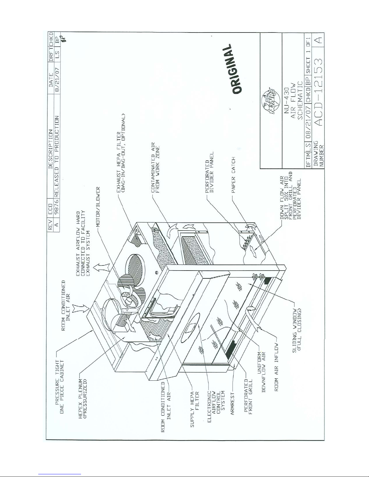
ACD‐12153....................................................NU‐430AirflowSchematic
BCD‐15501.....................................................NU‐430‐400SpecificationDrawing
BCD‐15502.....................................................NU‐430‐600SpecificationDrawing
BCD‐11815.....................................................DrainValveInstallation
BCD‐05572.....................................................ButterflyValveInstallation
BCD‐05660.....................................................BagIn/BagOutProcedure
ASSEMBLYDRAWINGS
BCD‐05147.....................................................BaseStandAssembly
BCD‐05146.....................................................BaseStandStorageCabinetAssembly
BCD‐11817.....................................................ControlCenter&FrontDecorativePanelAssembly
BCD‐11818.....................................................SlidingWindowAssembly&Adjustment
BCD‐14185.....................................................BaseCabinetAssembly
ELECTRICALSCHEMATICS
BCD‐16606(Sheets1‐2)................................NU‐430‐400/600ElectricalSchematic

OM0228Page5of99
February/2014
LabgardESEnergySaverClassII,
TypeB2LaminarFlow
BiologicalSafetyCabinet
Models
NU‐430‐400/600
MANUFACTUREDBY:
NuAire,Inc.‐Plymouth,Minnesota,U.S.A.
1.0 GeneralInformation
1.1Description
TheLABGARDESModelNU‐430LaminarFlowBiologicalSafetyCabinet(LFBSC)isabench/tabletopmodel,optionally
availablewithabasesupportstand,foroperationasaconsolemodel.TheLABGARDESmodelNU‐430utilizesanEnergy
SaverDCECMmotoroptimallydeterminedforwardcurvedfanforeachmodelsize/widthtomaximizebothenergy
efficiencyandfilterloadingcapacity.TheEnergySaverECMmotoriscontrolledtoairflowsetpointsviaasolid‐stateDC
motorcontrollerwithdigitaldualthermistorairflowsensorsthatprovideanautomaticcompensation(constantvolume
control)forbothfilterloadingandlinevoltagevariances.
TheLaminarFlowBiologicalSafetyCabinet,(LFBSC)isaproductresultingfromthedevelopmentofthe"laminarflow"
principleandtheapplicationofenvironmentalcontrolsasrequiredinthefieldofbiologicalresearchorchemical
containment.TheLFBSC,whenusedwithpropertechnique,isaneffectivelaboratoryaidinobtainingtheoptimumcontrol
overproductqualitywhilereducingthepotentialforexposureofbothproductandpersonneltoairbornebiologicalor
particulatechemicalagentsinlowtomoderaterisk‐hazardresearchanddrugpreparationorproductoperations,as
prescribedbytheCenterforDiseaseControl(CDC)Atlanta,Georgia.
TheNU‐430BenchLFBSCmeetstherequirementsofaClassII,TypeB2sincethecabinetconformstothefollowing
requirements:
-Maintainaminimumaverageinflowvelocityof100fpm(0.51m/s)throughtheworkaccessopening;
-HaveHEPAfiltereddownflowairdrawnfromthelaboratoryortheoutsideair(i.e.downflowairisnotre‐circulated
fromthecabinetexhaustair;
-Exhaustallinflowanddownflowairtotheatmospherethroughahardconnectiontothefacilityexhaustsystemafter
filtrationthroughaHEPAfilterwithoutrecirculationinthecabinetorreturntothelaboratory;
-Haveallcontaminatedductsandplenumsundernegativepressureorsurroundedbydirectlyexhausted
(non‐re‐circulatedthroughtheworkarea)negativepressureductsandplenums.
TypeB2cabinetsmaybeusedforworkwithnonflammableorexplosivevolatilechemicalsandradionuclidesrequired
asadjunctstomicrobiologicalstudies.

OM0228Page6of99
February/2014
1.2SafetyInstructions
ThesesafetyinstructionsdescribethesafetyfeaturesoftheLABGARDESModelNU‐430LFBSC.
Thesafetycabinethasbeenmanufacturedusingthelatesttechnologicaldevelopmentsandhasbeenthoroughlytested
beforedelivery.However,thecabinetmaypresentpotentialhazardsifitisnotinstalledandusedasinstructedforits
intendedpurposeoroutsideofoperatingparameters.Therefore,thefollowingproceduresmustalwaysbeobserved:
Thesafetycabinetmustbeoperatedonlybytrainedandauthorizedpersonnel.
Foranyoperationofthiscabinet,theoperatormustprepareclearandconcisewritteninstructionsforoperating
andcleaning,utilizingapplicablesafetydatasheets,planthygieneguidelines,andtechnicalregulations,in
particular.
oWhichdecontaminationmeasuresaretobeappliedforthecabinetandaccessories?
oWhichprotectivemeasuresapplywhilespecificagentsareused?
oWhichmeasuresaretobetakeninthecaseofanaccident?
Repairstothedevicemustbecarriedoutonlybytrainedandauthorizedexpertpersonnel.
Keeptheseoperatinginstructionsclosetothecabinetsothatsafetyinstructionsandimportantinformationare
alwaysaccessible.
Shouldyouencounterproblemsthatarenotdetailedadequatelyintheoperatinginstructions,pleasecontactyour
NuAireRepresentativeofNuAiretechnicalServices.
1.3ExplanationofSymbols
NOTE:
CAUTION used without the safety alert symbol
indicates a potentially hazardous situation which, if
not avoided, may result in property damage.
Potential electrical hazard, only qualified person
to access.
Used for important information.
Biohazard
Ground, Earth
CAUTION
Lead Free Chemical Hazard
Flammable Hazard
Hazardous Gases! Personal
Protection Equipment
Re
q
uired.
Safety alert symbol indicates a potentially hazardous
situation which, if not avoided, could result in death
of serious injury.
Safety alert symbol indicates a potentially hazardous
situation which, if not avoided, may result in minor or
moderate injury.
WARNING
!
CAUTION
!

OM0228Page7of99
February/2014

OM0228Page8of99
February/2014
2.0Models&Features
ThemodelNU‐430,LABGARDESClassII,TypeB2LaminarFlowBiologicalSafetyCabinetismanufacturedintwosizes:
4ft.(1.2m)and6ft.(1.8m).

OM0228Page9of99
February/2014

OM0228Page10of99
February/2014

OM0228Page11of99
February/2014
3.0Warranty
NuAire,Inc.warrantsClassII,TypeB2w/ECMMotor(LABGARDES)thatitwillrepairF.O.B.itsfactoryorfurnishwithout
chargeF.O.B.itsfactoryasimilarparttoreplaceanymaterialincludingsupplyHEPAfilter(excludingexhaustHEPAfilter)in
itsequipmentwithin60monthsafterthedateofsaleifprovedtothesatisfactionofthecompanytohavebeendefective
atthetimeitwassoldprovidedthatallpartsclaimeddefectiveshallbereturned,properlyidentifiedtothecompanyatits
factory,chargesprepaid.Factoryinstalledequipmentoraccessoriesarewarrantedonlytotheextentguaranteedbythe
originalmanufacturer,andthiswarrantyshallnotapplytoanyportionoftheequipmentmodifiedbytheuser.Claims
underthiswarrantyshouldbedirectedtoNuAire,Inc.settingforthindetailthenatureofthedefect,thedateoftheinitial
installationandtheserialandmodelnumberoftheequipment.
ThiswarrantyshallnotapplytoanyNuAireproductorpartthereofwhichhasbeensubjecttomisuse,abuse,accident,
shippingdamage,improperinstallationorservice,ordamagebyfire,floodoractsofGod.Iftheserialnumberofthis
productisaltered,removedordefacedastobeillegible,theWarrantyshallbenullandvoidinitsentirety.
Thewarrantyisforthesolebenefitoftheoriginalpurchaserandisnotassignableortransferable.Priortoreturningany
item,foranyreason,contactNuAireforaReturnAuthorizationNumber.Thisnumbermustaccompanyallreturns.Any
productshippedtoNuAirewithoutthisnumberwillbereturnedrefusedshipmentorcollectfreight.
4.0Shipments
NuAiretakeseveryreasonableprecautiontoassurethatyourLABGARDEScabinetarriveswithoutdamage.Motorcarriers
arecarefullyselectedandshippingcartonshavebeenspeciallydesignedtoinsureyourpurchase.However,damagecan
occurinanyshipmentandthefollowingoutlinesthestepsyoushouldtakeonreceiptofaNuAireLABGARDEScabinetto
besurethatifdamagehasoccurred,theproperclaimsandactionsaretakenimmediately.
4.1DamagedShipments
4.1.1Termsarefactory,unlessstatedotherwise.Therefore,itisimportanttocheckeachshipmentbeforeacceptance.
4.1.2Ifthereisvisibledamage,thematerialcanbeacceptedafterthedrivermakesanotationontheconsignee'scopy
ofthefreightbill.Thenaninspectionmustbemadetoverifytheclaimagainstthecarrier.Thisinspectionisthe
basisofyourfilingtheclaimagainstthecarrier.
4.1.3IfconcealeddamageisfounditisabsolutelynecessarytoNOTIFYTHEFREIGHTAGENTATONCEandrequestan
inspection.Withoutthisinspection,thetransportationcompanymaynotacceptaclaimforlossordamage.Ifthe
carrierwillnotperformtheinspection,anaffidavitmustbepreparedstatingthathewascontactedonacertain
dateandthathefailedtocomplywiththerequest.Thisalongwithotherpapersinthecustomer'spossessionwill
supporttheclaim.

OM0228Page12of99
February/2014
5.0InstallationInstructions
5.1Location
Withinthelaboratory,pharmacy,etc.,theideallocationofthebiologicalsafetycabinetisawayfrompersonneltraffic
lanes,airvents(inorout),doorsand/oranyothersourceofdisruptiveaircurrents.
Ifdraftsorotherdisruptiveaircurrentsexceedtheinflowvelocityofthecabinetthroughtheaccessopening,thepotential
existsforcontaminatedairtoexitorentertheworkzoneareaofthecabinet.Itdependsontheseverityoftheaircurrent.
REMEMBER:ABIOLOGICALSAFETYCABINETISNOSUBSTITUTEFORGOODLABORATORYTECHNIQUE.
Wherespacepermits,aclear6inch(152mm)areashouldbepermittedoneachsideofthecabinetformaintenance
purposes.Theelectricaloutletintowhichthecabinetisconnectedshouldbereadilyaccessibleformaintenancepurposes.
Donotpositionthecabinettopreventaccesstothepowercord.Thepowercordplugservesasthedisconnectand
shouldremainreadilyaccessible.Iftheoutletisinaccessible,suchasaconduit(hardwired)connection,thenanappropriate
warninglabelshouldbeappliednearthecabinet'son/offswitch,toindicatethecircuitbreakeronthepowerdistribution
paneltobeused.
Morethananyotherbiologicalsafetycabinet,theNU‐430requirescarefulsite‐planningandpreparation,duetothetotal
exhaustnatureofthecabinet.Propersizingoftheexhaustandmakeupsupplysystemsarecriticaltothesuccessful
installationofthecabinet.Inaddition,thecabinetprovidesforthechoiceofmake‐upairforthesupply(downflow)air.
Thefollowingareairflowrequirementsbasedonconcurrentbalancevalues*.
AirVolume(CFM/CMH)SupplyAirInflowExhaustAir**
NU‐430‐400440/748345/586785/1334
NU‐430‐600719/1222531/9021250/2124
*ConcurrentBalanceValueisdeterminedbyaducttraversemeasurementmethodasspecifiedinASHRAEStandard111at
itsnominalsetpointcalibratedusingtheprimaryDIMmethodandcapturehoodremoved.Thesevaluesshallbeusedfor
designandbalanceexhaust/supplyHVACrequirements.
**Exhaustairvolumeatnegative1.7inches(43mm)w.g.forNU‐430‐400and
1.8inches(46mm)w.g.forNU‐430‐600.

OM0228Page13of99
February/2014
5.2Set‐UpInstructions
Removeoutershippingprotection(cartonorcrating).Thecabinetisfastenedtothebaseskidanditisusuallythebest
proceduretoleavetheskidinplaceuntilthecabinetislocatedinitsapproximatepositiontofacilitateeaseinhandling.
Itcanthenberemovedfromtheskidbyremovingthebandingholdingthecabinettotheskid.Itmaybenecessaryto
removetheControlCenterinordertogainpassagethroughadoorway.Itmayeasilyberemovedbyfollowingthe
instructionsondrawingBCD‐11817.
Itisrecommendedthatnolessthantwopeoplearepresentusinga
liftingsystemforplacementofthecabinetontothebasestand.
Itisnotrecommendedtomanuallyliftthecabinetontothebasestand.
5.2.1BaseStandAssembly
ThebasestandisshippedknockeddowninaseparatecartonandisassembledperdrawingBCD‐05147if
accompaniedwiththecabinet.Removethebandingholdingthecabinettothebaseskid.Liftthecabinetfrom
thebaseskidandplaceonthefloor.Nowliftthecabinetontopofthebaseandboltthebasestandtothecabinet
usingtwo3/8"‐16x3/4"boltsandwashersprovidedforthefrontbasestandtabsandtwo1/4"acornnutsfor
therearweldstuds.Placethecabinetinitsdesiredlocation.
Thebasestandstoragecabinetswillusuallybeshippedaccordingtocustomerrequirements.Ifitisshipped
unassembled,itcanbeassembledperdrawingBCD‐05146.Itisrecommendedthattheupperandlowerbase
standbracesbeinstalledfirst,thentherearandbottompanels(theendpanelsarealwaysprefastened).Once
assembled,fastenthecabinetpertheaboveinstructions.
Removethecapprotectingthedrainvalvethreadsandinstallthedrainvalve,onthebottomrightfrontofthe
cabinetusingLoctite242furnishedtothethreadsandrotatethevalvebodyuntilitissecure(SeeBCD‐11815).
5.2.2Leveling
Usingalevelplacedontheworktray,adjusttheleglevelers,first,end‐to‐endthenfronttoback.
TheNSFapprovedleglevelersprovidea3/4"(20mm)adjustment.
5.2.3BenchInstallation(BCD‐11815)
Placethecabinetonthebenchwithapproximatelya2"(51mm)overhangclearanceforinstallationofthedrain
valve.Ifthedrainvalveisnotdesired,capwith3/8”NPTfittingandplacethecabinetinitsdesiredlocationand
usingRTVcaulk,sealallaroundthebaseofthecabinetandthebench.Thisprovidesatightsealtopreventbench
spillsfrommigratingunderthecabinet.
Ifadrainvalveisdesired,(NOTE,CHECKWITHYOURSAFETYPERSONNELFORREQULATORYREQ
UIREMENTS(i.e.
LOCKINGTYPE)OFDRAINVALVEINSTALLATION)removethehandlefromthevalvestemtogainclearancefor
valvebodyrotation.AddLoctite242(furnished)tothethreadsandrotatevalvebodyuntilsecure,withthevalve
stem(forhandle)ontheleftside.Re‐installhandletovalvestem.Adjustthecabinetonbenchtoprovidea
1‐1/2"(38mm)overhangandsealtheinterfaceofthebenchandcabinet,usingRTVcaulkasabove.
CAUTION
!

OM0228Page14of99
February/2014
5.2.4GasService
NuAiredoesn'trecommendtheuseofnaturalgaswithintheLFBSC,butifgasserviceisdeterminedtobe
necessaryfortheapplication,appropriatesafetymeasuresmusttakeplace.AllNuAireLFBSC'shaveprecautionary
warninglabelsthatsaythefollowing:
Useofexplosiveorflammablesubstancesinthiscabinet
shouldbeevaluatedbyyourappropriatesafetypersonnel.
Oncetheappropriatesafetypersonnelhavemadethedetermination,theapplicationofnaturalgasmust
beperformedinaccordancetonational,stateandlocalcodes.ITISALSOSTRONGLYRECOMMENDEDTHATAN
EMERGENCYGASSHUTOFFVALVEBEPLACEDJUSTOUTSIDETHELFBSCONTHEGASSUPPLYLINE.
AllNuAireLFBSC'smeetthesafetyrequirementsofULandCSAforLaboratoryEquipment.Tocomplywiththese
safetyrequirements,NuAireusesonlycertifiedgasvalves.Inaddition,ifexternalpipingisrequired,onlyblack
pipeisusedforthisapplication.
AspreviouslystatedNuAiredoesn'trecommendtheuseofnaturalgaswithintheLFBSCandASSUMESNO
RESPONSIBILITYFORITSUSE.USEATYOUROWNRISK.TheBunsenburnerflamewithintheLFBSCnotonly
contributestoheatbuild‐up;isalsodisruptsthelaminarairstream,whichmustbemaintainedformaximum
efficiency.IFTHEPROCEDUREDEMANDSUSEOFAFLAME,ABUNSENBURNERWITHONDEMANDIGNITIONIS
STRONGLYRECOMMENDED.DONOTUSECONSTANTFLAMEGASBURNERS.Duringuse,theBunsenburner
shouldbeplacedtotherearoftheworkspacewhereresultingairturbulencewillhaveaminimaleffect.
5.2.5PlumbingServices
Serviceballvalveswiththetypeofservicespecifiedbytheremovablebuttononthehandlearelocatedinthe
workzone.Theserviceballvalvesarenotrecommendedforpressureover75p.s.i.(5.2BAR).Reducingvalves
shouldbeinstalledexternaltothecabinetifnecessary.Serviceballvalvesshouldneverbeusedforflammable
gassesoroxygenservice.Aspecialneedlevalveforoxygenserviceorcertifiedvalveisrequiredandavailableupon
request.
Externalconnectionisto3/8inchNPTcouplingintheinnersidewalls.Connectiontoplantutilitiesshouldbe
madewithpropermaterialsfortheindividualserviceandaccordingtoNationaland/orLocalcodes.Observeall
labelspertainingtothetypeofserviceandoperatingpressure.
Remotecontrolledneedle‐valveplumbingfixturescanbeoptionallyprovidedwithintheinteriorsidewalls.Control
handlesarelocatedexternallyontheverticalairfoil.Serviceoutletswithintheinteriorhaveserratedtapered
fittingsdesignedforhoseconnectionswiththeremotecontrolledneedlevalveplumbingfixtures.NuAireprovides
forrear,bottom,ortopconnectionsofplumbingservicestoplantutilities.Connectionfromtheneedlevalve
assemblytotheweldedexitcouplingisaccomplishedwiththesupplied3/8inchsoftcoppertubingasstandard
(alternativematerialstomeetlocalcodesareavailableuponrequest).Theneedlevalvesarenotrecommended
forworkingpressureinexcessof125p.s.i.(8.6BAR).
5.2.6ElectricalServices
TheNU‐430seriesBiologicalSafetyCabinetsmaybe"hardwired"(optional)orpluggedintoanoutletwith
protectiveearthingconnectionwiththestandardpowercord.Thecabinetrequires115VAC,60Hzsinglephase
(correctratingvariespercabinetsize,referenceElectrical/EnvironmentalRequirements).Itisrecommendedthat
powertothecabinet,whetherhardwiredorplugconnected,beonitsownbranchcircuit,protectedwithacircuit
breakeratthedistributionpanelnearthecabinet.Asurgeprotectorisstronglyrecommendedifyouare
experiencingpowerrelatedfaults.
PLEASENOTETHISCABINETCONTAINSELECTRONICBALLASTSFORTHEFLUORESCENTLIGHTING.ELECTRONIC
BALLASTSOPERATEWITHHIGHINRUSHCURRENT.ITISNOTRECOMMENDEDTOUSETHISPRODUCTWITH
GROUNDFAULTCIRCUITINTERRUPTERS(GFCI'S)BECAUSETHEBALLASTSMAYCAUSETHEGFCITOTRIP.
CAUTION
!

OM0228Page15of99
February/2014
5.2.7Exhaust/SupplyDuctInstallationGuidelines
Theexhaust/supplysystemsmustprovideconditionssimilartothatunderwhichthecabinetwascertifiedtomeet
itsstatedperformance.Thefollowingguidelinesshouldbeobservedwheninstallingexhaust/supplyairductwork
foreitherexistingplantexhaustsystems,oranewexhaustsystem.
1.Adequateroommake‐upairinflowtoreplaceexhaustedair.Airdiffusionrateisnottoexceedvelocityof
100LFPM(.51m/s)tominimizedisruptiveaircurrents.Iflaboratoryistobepressurized,follow
guidelinesinANSI/AIHAZ9.5LaboratoryVentilation.
RoomMake‐UpAirRequirements(CFM/CMH)UtilizingConcurrentBalanceValues
ModelWithSupplyDuctWithoutSupplyDuct
NU‐430‐400345/586785/1334
NU‐430‐600531/9021250/2124
2.Adequateplantexhaustsystemcapability.Theexhaustsystemisusuallyadequateifitcanprovidethe
ratedexhaustflowandstaticpressure.
3.Allductlossesmustbeconsideredandaddedtothecabinetlossinselectingtheexhaustblower,fora
newexhaustsystem(i.e.ductdiameter,lengthandnumberofelbows,etc.).
4.Adequatesupplyaircapability(ifused).Thesupplyairsystemisusuallyadequateifitcanprovidethe
ratedsupplyairat0.0incheswatergaugepositive.
5.Thesupplyairmustbeinterlockedwiththeoperationofthecabinet'sinternaldownflowblowerinorder
topreventdownflowairfrombeingforcedoutofthefrontofthecabinetwhenpoweredofforduring
nightsetbackconditions.NuAireprovidesfanrelaycontactsforthispurpose.
6.Allductworkshouldbesecurelyanchoredtothebuildingconstructioninmannertobefreefrom
vibrationandswayingunderallconditionsofoperations.
7.SheetmetalgaugesandseamsshouldbeinaccordancewiththecurrenteditionoftheASHRAEguide.
Aminimumof20gaugeforroundductisrequiredtopreventductcollapseduetohighstaticpressure
conditions(squareductwillrequireheaviergaugematerial).
8.Allductworkshouldbemaintainedatanegativepressurewithinthebuilding(i.e.externallylocated
exhaustblower).
9.Theexhaustblowerandductworkshouldbeasealedsystemthatcanhold2.0inches(51mm)w.g.
pressurefor30minuteswithnomorethana10%dropinpressure,andbeproperlyventedtothe
atmospheretodisperseexhaustedair.
10.Alocalmanualexhaustflowdamper(NuAireModelNU‐940)shouldbereadilyaccessible(eitherdirectly
mountedontheLFBSCexhaustcollarorjustabovetheLFBSC)forthemaintenancetechnician/certifierto
allowtheLFBSCtobesealedfordecontaminationpurposes.IfaConstantAirVolume(CAV)valveis
locatedabovetheLFBSC,anyexhaustflowadjustmentsshouldbemadetotheCAVvalveleavingthe
manualexhaustdamperinafullopenposition.
11.Itisrecommendedthatthecabinetoperationbeinterlockedwiththeexhaustblower.Fanrelaycontacts
areprovidedforthispurpose.However,itisalsorecommendedtohaveamanualexhaustoverride
switchnearthecabinetforcertificationandservice.Formulti‐gangedsystems,thisswitchcouldbeused
tointerfacewithaBuildingAutomatedSystem(BAS).
12.ItisrecommendedthatwhenusingtheNU‐951‐012automaticbutterflyvalve,thesystemairvolume
mustremainwithintenpercentofthegivennominalsetpointvolumetooptimizethemeasurementand
controlperformance.
13.Itisnotrecommendedtohardconnect(i.e.weld)theexhaustconnectiontothecabinet.Thismay
damagetheexhaustfilterand/orthebutterflyvalve(ifpresent).Asiliconsleeve(NuAirePartNo.NU‐
940‐001),bandedbetweenthecabinet'sexhaustductandtheplantexhaustductisrecommended,with
nomorethanatwo‐inchgapbetweentheducts,fora1/8inch(3mm)thicksiliconesleeve.IfNuAire
dampervalvesarepresent,seeDrawingBCD‐05572forinstallation.
14.Ifductdiameterreductionisrequired,itisrecommendedthatthereductionoccursatleast12inches
(305mm)fromthecabinetductconnectionandthatthereductionissmoothandgradualtoreduceair
turbulencethatresultsinnoiseandlossofstaticpressure.
15.ITISNOTRECOMMENDEDTOCONNECTTHECABINETDUCTCONNECTIONDIRECTLYINTOA90‐DEGREE
BEND.Thecabinet'sexhaustairflowsensorcouldbeaffectedbyairflowturbulencecreatedby90‐degree
bends.Ifa90‐degreebendisrequired,itisrecommendedthatthe90‐degreebendoccuratleast12
inches(305mm)fromtheLFBSCexhaustcollar.

OM0228Page16of99
February/2014

OM0228Page17of99
February/2014

OM0228Page18of99
February/2014
5.2.8FinalAssembly
Removetheprotectivecardboardcoveroverthesupplyandexhaustconnectionsontopofthecabinet.The
exteriorsurfaceandviewingglassareeasilycleanedwithanymildhouseholddetergentcleanerusingasoftcloth.
Harshchemicals,solvent‐typecleanersandabrasivecleanersshouldnotbeused.
DonotattempttocleantheHEPAfiltermedia.Cabinetinteriorwallsorworksurfaceareeasilycleanedwithany
mildhouseholddetergentcleanerusingasoftcloth.Turnthecabinetonandletitoperatefor60minutesbefore
usingitasaLFBSC.
5.3Exhaust/SupplyAirChecks
NOTE:THEINTERNALSUPPLYBLOWERISINTERLOCKEDWITHTHEEXHAUSTSENSOR,
TOPREVENTOPERATIONUNLESSADEQUATEEXHAUSTFLOWISPRESENT.
5.3.1ExhaustVolume/InflowVelocity
Theexhaustvolumeandcorrespondinginflowvelocityisdisplayedonthefrontpanel.Presetlowerandupper
alarmlimitsarefactorysetbutcanbefieldverifiedatanytime.Toinsurethatadequateexhaustisavailablefora
dirtyexhaustHEPAfilter,condition,thenominalexhaustreadingsshouldbeattainablewiththebutterflyvalveor
dampersetat60percentopen,withallotherdampersinthesystem(duct)open.
5.3.2SupplyVelocity
ThesupplyvolumeiscontrolledbytheBSCCairflowcontrolsystem.TheBSCCsystemusesadualthermistor
airflowsensorinthedownflowairstreamtomonitorandcontrolairflowtosetpoint.Thecontrolsystem
automaticallycompensatesforfilterloading,voltagevariancesandotherenvironmentaleffects.However,
excessivevariancescausedbyremotebutterflyvalvesordampers,insufficientsupplyairanddirtyprefiltersmay
causeanairflowalarmconditiontooccur.
NOTE:THESUPPLYAIR,IFINTEGRALLYDESIGNED,MUSTBEINTERLOCKEDWITH
THEINTERNALFANRELAYTOASSUREPROPEROPERATION.

OM0228Page19of99
February/2014
5.4CertificationTestingMethodsandEquipment
Afterinstallationandpriortouse,NuAirerecommendsthatthecabinetbecertifiedorcommissionedtofactorystandards.
Asapartofcertification,thecertifiershouldgothroughthefollowinginitialchecklisttoassureallaspectsoftheLFBSC
installationarecompleteandreadyforcertification.
Reviewproductinstallation
Exhaustconnection
Dampervalveinstalledcorrectlywithlabeltowardfront
LFBSCbasestandlevel
Verifyairflowsensorshroudisinplace
Downflow
Verifyconfigurationtypeselectionforspecificmodel*(seesection7.5.2)
Verifysetpointsandalarmlimitsforspecificmodel*(seesection7.5.2)
PerformBCScertification
Ataminimum,thefollowingtestsshouldbeperformed:
HEPAfilterleaktest
Downflowvelocitytest
Inflowvelocitytest
Airflowsmokepatterns
Siteinstallationassessmenttests
PerformSiteAssessmentTests
TheNU‐430requiresverificationofthesupplyfaninterlockandback‐uppressureswitchoperationutilizing
independentexhaustvolumemeasurementinstrument(DIM).PerNSF/ANSI49,a20%lossofexhaust
volumemustproduceanairflowalarmwithin15seconds.
Thetestingmethodsandequipmentrequiredarespecifiedonthefactoryinspectionreportincludedwiththismanual.
(Seeinsertinbackcover)
NOTE: ITISRECOMMENDEDTHATTHESETESTSBEPERFORMEDBYAQUALIFIEDTECHNICIANWHOIS
FAMILIARWITHTHEMETHODSANDPROCEDURESFORCERTIFYINGBIOLOGICALSAFETYCABINETS
(SEEINSERT)
NOTE: AFTERTHEINITIALCERTIFICATION,NUAIRERECOMMENDSTHATTHECABINETBERECERTIFIED(ATA
MINIMUM)ONANANNUALBASISANDAFTEREVERYFILTERCHANGEORMAINTENANCEACTIONOR
ANYTIMETHEOPERATORFEELSITISNECESSARY.
NotethattheLABGARDEScabinets,filters,andsealsprovidepremiumperformance.QualityControlinbothdesignand
manufacturingassuresuperiorreliability.However,protectiontobothproductandoperatorissovitalthatcertificationto
theperformancerequirementsshouldbeaccomplishedasstatedtoensurebiologicalsafetyestablishedbythefactory
standards.
*Ifthespecificmodelisaspecialproductwithnon‐standardsetpointsandalarmlimits,thenewvalueswill
belocatedonthefactoryInspectionReport.

OM0228Page20of99
February/2014
LabgardESEnergySaverClassII,TypeB2LaminarFlowBiologicalSafetyCabinet
ModelsNU‐430‐400/600
CatalogNumber
CatalogNumberNU‐430‐400
Nominal4foot(1.2m)
NU‐430‐600
Nominal6foot(1.8m)
PerformanceSpecifications
1.PersonalProtection
2.ProductProtection
NSF/ANSI49
NSF/ANSI49
NSFStd.No.49ClassClassII,TypeB2ClassII,TypeB2
StyleofCabinetBenchTop/Consolew/BaseStand/
StorageCabinet
BenchTop/Consolew/BaseStand/
StorageCabinet
CabinetConstructionAllWeldedStainlessSteel16GA,
Type304PressureTightDesign
AllWeldedStainlessSteel16GA,Type
304PressureTightDesign
DiffuserforAirSupply(Metal)Non‐FlammableNon‐Flammable
HEPAFilterSealType:
SupplyFilter‐99.99%Eff.on0.3Microns
ExhaustFilter‐99.99%Eff.on0.3Microns
HEPEXSeal
Neoprene,Springloaded
HEPEXSeal
Neoprene,Springloaded
FumigationperNIH/NSFProcedureYesYes
StandardServices:
ServiceCoupling(3/8inchNPT)
GasValve/ServiceCoupling(3/8inchNPT)
DuplexOutlet
None
Two,RightSidewall
One,LeftFrontFaring
None
Two,RightSidewall
One,LeftFrontFaring
OptionalServices:GasCocks3/8"NPT
**RemoteControlledValves
UltravioletLight
Standard/CupSinks
Upto3ea.Sidewall
Upto3ea.Sidewall
One,Backwall
LeftorRightWorkSurface
Upto3ea.Sidewall
Upto3ea.Sidewall
One,Backwall
LeftorRightWorkSurface
CabinetSizeInches(mm):
Height(FullyAssembled)
Height(MinimumforTransport)
Width
Depth(withControlCenter)
61(1549)
61(1549)
535/8(1362)
327/8(835)
61(1549)
61(1549)
775/8(1972)
327/8(835)
WorkAccessOpeningInches(mm):
StandardOpeningHeight
StandardInflowVelocity
8(203)
105FPM(.53m/s)
8(203)
105FPM(.53m/s)
WorkZoneInches(mm):Height
Width
Depth
251/2(648)
463/8(1178)
251/2(648)
703/8(1788)
231/2(597)
ViewingWindowInches(mm):
StandardisTemperedSlidingGlass
HingedTemperedGlass(optional)
1.0(25mm)Closed
181/2(470)Open
8(203)AccessOpening
1.0(25mm)Closed
181/2(470)Open
8(203)AccessOpening
CertificationExhaustValueCFM/CMH
ConcurrentBalanceValueCFM/CMH+
754/1281
785/1334
1100/1867
1250/2124
PlantDuctStaticPressureEng./Metric1.7”w.g./43mmw.g.1.8”w.g./46mmw.g.
HeatRejected,BTU,PerHour474584
Electrical:115V
Volts,AC(Hz)
++Amps:Blower/Lights
Amps:Outlet
RatedAmps:
12ft.PowerCord(one)
U.L./UL‐C,USListed
115,60
2.1
3
10
14GA‐3Wire,15A
U.L./UL‐C,USListed
115,60
2.6
3
10
14GA‐3Wire,15A
CratedShippingWeight:
NetWeight
570lbs./259kg.
520lbs./236kg.
760lbs./345kg.
710lbs./322kg.
**Remotecontrolledvalvehandlesprojectthroughfrontfairing.Decorativesidepanelsareavailabletocoverplumbing.
+ConcurrentBalanceValueshallbeusedfordesignandbalanceexhaust/supplyHVACrequirements.
++Basedoncabinetwithnewfiltersrunningat115VAC.
This manual suits for next models
3
Table of contents
Other NuAire Air Conditioner manuals
Popular Air Conditioner manuals by other brands

Cooler Master
Cooler Master Silent Pro Gold 450W user manual

Innova
Innova IGZCAPS NI Series owner's manual

Mitsubishi Electric
Mitsubishi Electric MSC-GE20VB operating instructions

Tycoon
Tycoon TS2MVI32-09 Service manual

Samsung
Samsung AR18NSWSPWKXCV Service manual

Trane
Trane Packaged TerminalAir Conditioners & Heat... Installation operation & maintenance

Technibel
Technibel KPAFP125R5IA Series instruction manual

Mitsubishi Electric
Mitsubishi Electric MSZ-FA25VA Service manual

Dimplex
Dimplex DCEVP5WG instruction manual

Fujitsu
Fujitsu AGYG09LVCB Service manual

Toshiba
Toshiba RAS-10J2KV-HK owner's manual

Haier
Haier HBU-18CA03T3 Operation & installation manual