NuAire NEPTUNE T-AT User manual

1
03. 09. 20. Document Number 671935Nuaire | Western Industrial Estate | Caerphilly | CF83 1NA |nuaire.co.uk
NEPTUNE T-AT
Thermal Wheel AHU with
Adapt Trend (AT) Control
Installation Manual
EMC Directive
2014/30/EU
LVD Directive
2014/35/EU
1.0 SAFETY INFORMATION
• The provision of the electrical supply and the connection of the unit to the mains must be
carried out by a qualified electrician.
• Isolate from power supply before removing any covers. During installation / maintenance ensure
all covers are fitted before switching on the mains supply.
• All-pole disconnection from the mains as shown in the wiring diagram must be incorporated
within the fixed wiring and shall have a minimum contact separation of 3mm in accordance with
latest edition of the wiring regulations.
• This unit must be earthed.
• Ducting must be securely fixed with screws to the spigot to prevent access to live parts. Duct
runs terminating close to the fan must be adequately protected by suitable guards.
• If the supply cord is damaged, it must be replaced by the manufacturer, its service agent or
similarly qualified persons in order to avoid a hazard.
• Precautions must be taken to avoid the back-flow of gases into the room from the open flue of
gas or other fuel-burning appliances.
• This appliance should not be used by children or persons with reduced physical, sensory or
mental capabilities or lack of experience and knowledge, unless they have been given supervision
or instruction concerning the safe use of the appliance by a person responsible for their safety.
Children shall not play with the appliance. Cleaning and user maintenance shall not be carried
out by children.
1.1 Symbols
GENERAL WARNING
Signifies a general warning regarding hazard specified by supplementary information.
ELECTRIC SHOCK
This unit must be completely electrically isolated before any panels are removed. Check
mains supply and control connections.
ROTATING PARTS
This unit contains fast moving rotational parts which may start automatically. It is the
sole responsibility of the installer to adequately guard these components.
REFER TO INSTRUCTION MANUAL
Read and understand the installation and maintenance manual before installing,
operating or maintaining this product.

2
03. 09. 20. Document Number 671935Nuaire | Western Industrial Estate | Caerphilly | CF83 1NA |nuaire.co.uk
NEPTUNE T-AT
Installation Manual
1.2 Important Information
This manual contains important information on the safe and
appropriate assembly, transport, commissioning, operation,
maintenance, disassembly and simple troubleshooting of the product.
While the product has been manufactured according to the accepted
rules of current technology, there is still a danger of personal injury or
damage to equipment if the following general safety instructions and
the warnings contained in these instructions are not complied with.
•Read these instructions completely and thoroughly before
working with the product.
•Keep these instructions in a location where they are accessible
to all users at all times.
•Always include the operating instructions when you pass the
product on to third parties.
1.3 Personal Protective Equipment
The following minimum Personal Protective Equipment (PPE) is
recommended when interacting with Nuaire products:
•Protective Steel Toed Shoes - when handling heavy objects.
•Full Finger Gloves (Marigold PU800 or equivalent) - when
handling sheet metal components.
•Semi Fingerless Gloves (Marigold PU3000 3DO or equivalent)
- when conducting light work on the unit requiring tactile
dexterity.
•Safety Glasses - when conducting any cleaning/cutting operation
or exchanging filters.
•Reusable Half Mask Respirators - when replacing filters which
have been in contact with normal room or environmental air.
Nuaire would always recommend a site specific risk assessment by a
competent person to determine if any additional PPE is required.
2.0 INTRODUCTION
The packaged supply and extract unit shall be manufactured from
Aluzinc corrosion resistant steel, with 50mm double skinned panels
and anodized aluminium frame. All external fittings and fixings shall be
stainless steel, aluminium or non-metallic. All panels and frames will
be of a totally thermally broken design, complying with the following
specification in accordance with BS EN 1886: Mechanical strength, D1;
Leakage class, L2; Thermal transmittance, T3; Thermal bridging, TB3.
Panels and frames will be sealed without the use of silicon, mastic or
other liquid gasket.
An ERP compliant heat exchanger with automatic bypass, complete
with a condensate tray (where cooling is fitted) included. An F7 main
supply filter shall be fitted with an M5 filter bank present on the extract
side. Rails for an additional supply G4 panel filter shall be present with
pressure drop monitoring for maintenance notification included.
Performance optimised backward curved impellers and IP54 EC motors
shall be used to provide low specific fan powers and step less speed
control without tonal noise generation. Fan pressure transducers shall
be fitted (Connect control only) for constant pressure/ flow control and
energy monitoring.
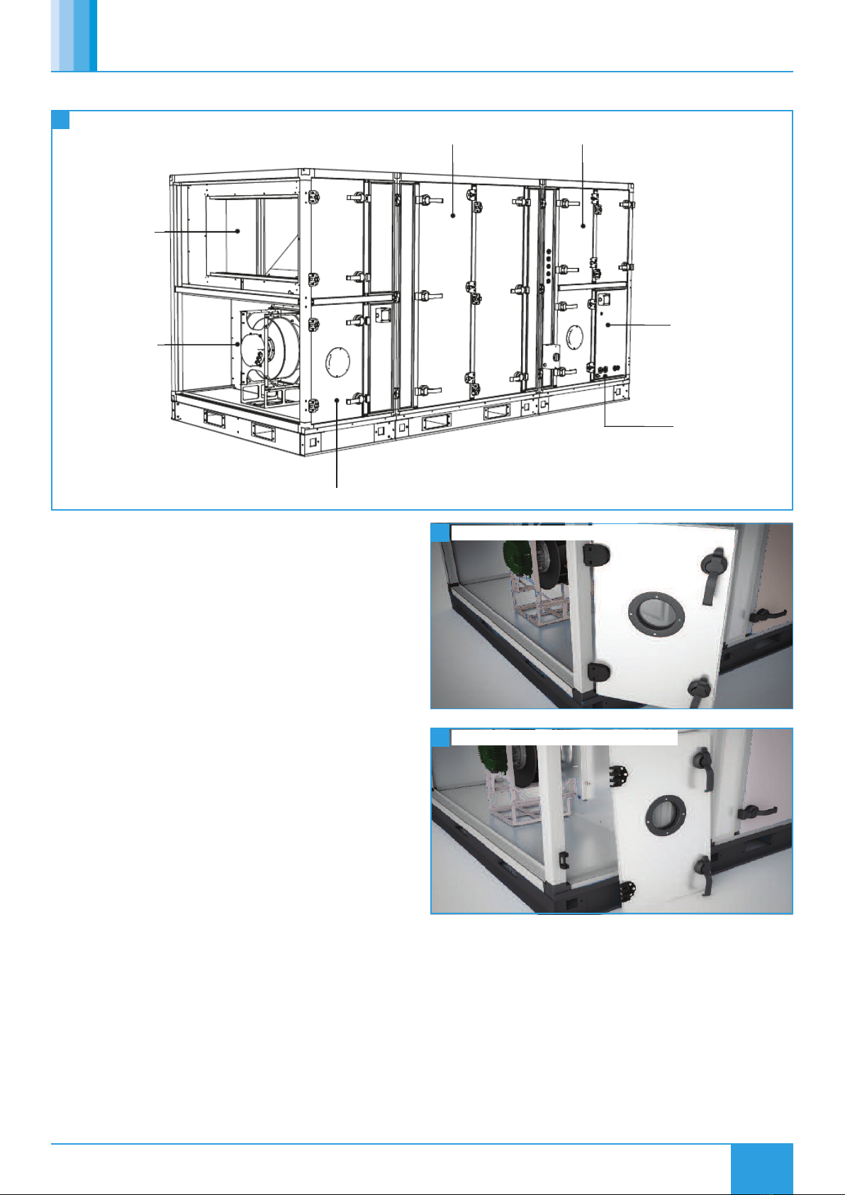
All hinged access panels shall be lockable and removable (with a
common key for all) allowing full maintenance access from the side.
The unit has left (and right option) hand arrangement in direction of
supply air flow.
A LPHW heater battery shall be fitted (on LPHW units). An electric
heater module shall be present (on Electric heater units), complete
with power controller to allow output modulation from the unit
control. A fail-safe auto-reset safety device shall be present.
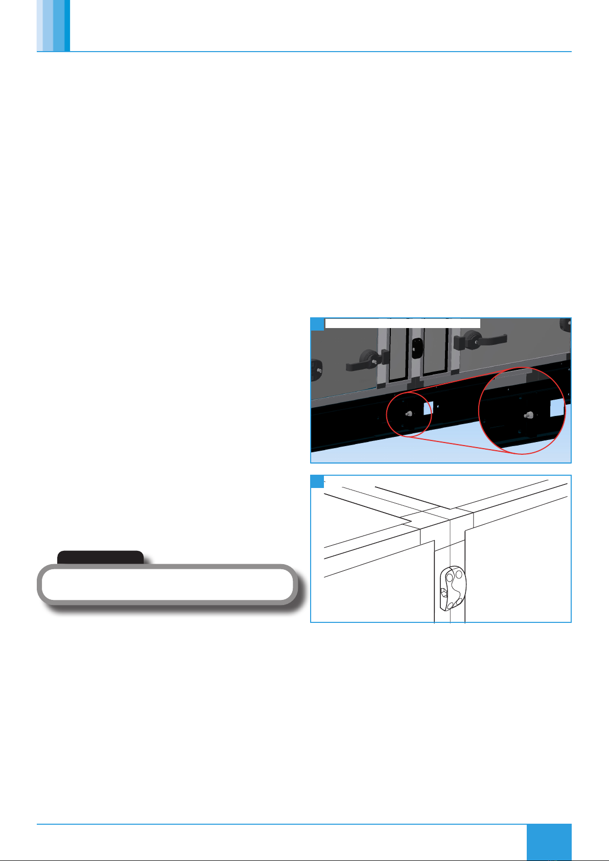
Structural base frames shall be fitted, powder coated with
covered forklift slots and 50mm square lifting bar holes for site
manoeuvrability. Three axis alignment clamps shall be fitted externally.
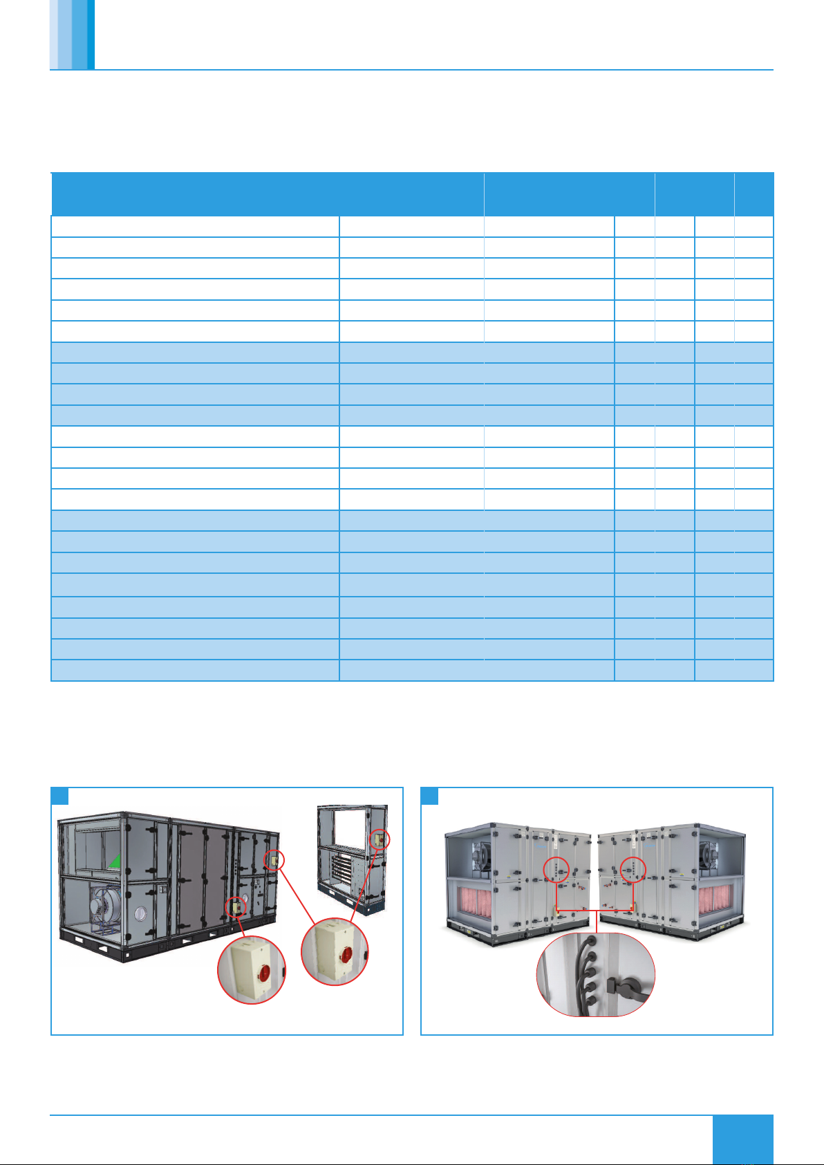
An IP66/67 lockable isolator shall be present for power connection on
main and electric heater modules. Sealing grommets will be present for
control cable access to the unit internals without the need for drilling
on site. Module electrical interconnection shall be made using pre-
fitted plug and socket arrangements.
Modules shall be provided with identification labelling to aid assembly
and QR coded badges to simplify document retrieval via portable
devices.
Autodesk REVIT files shall be provided for Building Information
Modelling and all units shall be based on performance testing carried
out within an AMCA certified test laboratory.
2.1 Code Description:
N 07 T / L R / ES - L WP 4
123/45 / 6 - 7 8 9
1. Range: N = Neptune AHU
2. Unit Size: 07, 12, 17, 22, 32, 42 or 55
3. Heat Recovery Type: T= Thermal Wheel
4. Heating Type: E= Electric (07 - 42 Only)
L = Low Pressure Hot Water (LPHW)
N = No Heating
Cooling Type: C= Chilled Water (CW)
N = No Cooling
X= Reverse Cycle DX (condenser unit
and controls by others)
5. Control Type: AT = Adapt Trend
6. Access Handing L = Left Hand
(in direction of supply R = Right Hand
airflow)
7. Unit Roof: No Affix = Standard Unit (No Roof)
WP = Roof (Factory Fitted)
8. Unit Finish: No Suffix = Standard
4 = Coastal (C4**)
** This units coastal finish has been designed to withstand an External
C4 Atmospheric Corrosivity Category as per BS EN ISO 12944-2:2017
providing that it is installed and maintained as per the manufacturer’s
instructions and general Warranty Guidance Notes found in our
conditions of sale.
3.0 DELIVERY & RECEIPT OF EQUIPMENT
All equipment is inspected prior to despatch and leaves the factory in
good condition. Upon receipt of the equipment an inspection should be
made and any damage indicated on the delivery note.
Particulars of damage and/or incomplete delivery should be endorsed
by the driver delivering the goods before offloading by the purchaser.
No responsibility will be accepted for damage sustained during the
offloading from the vehicle or on the site thereafter.
All claims for damage and/or incomplete delivery must be reported to
Nuaire within two days of receipt of the equipment.

3
03. 09. 20. Document Number 671935Nuaire | Western Industrial Estate | Caerphilly | CF83 1NA |nuaire.co.uk
NEPTUNE T-AT
Installation Manual
3.1 Unit Offloading and Handling
The weight of unit modules and palletised items is displayed on the
packaging. Some of the modules have an uneven weight distribution
and this will be indicated by labelling where appropriate.
Offloading and positioning of the equipment is the responsibility of
the purchaser, and should only be performed by competent personnel
following an appropriate risk assessment.
To ensure that the delivery vehicle is loaded according to the
planned method of offloading, Nuaire must be notified to ensure
coordination. When offloading, care must be taken to ensure that the
AHU is kept level at all times.
Palletised. Forklift. Assembly with
base frame.
Slings via spreaders fitted to
unit with base frame.
Please note that above images are examples of typical lifting methods.
Actual unit lifting plan and risks must be assessed by competent personnel before moving the unit.
1 Typical Methods of Lifting
To ensure that no roof damage occurs additional timber packaging
must be used.
3.2 Base Frame Lifting Points
When units are constructed of multiple modules each module will have
it’s own individual base frame, which is then connected to the next to
assemble the full system.
All base frame sections will have 50mm square lifting holes at the
end of each side to enable lifting. In addition to this, covered fork
lifting channels are located across the width of the base frame, if the
module length is sufficient to allow this. For shorter modules the fork
lifting points will be along the length of the section, without a covered
channel (Figure 2).
2 Base Frame Detail
Section length Section lengthSection length
Section width
50.0
50.0
50.0
50.0
50.0
100.0
100.0
100.0
Overall unit length
150
CENTRE SUPPORT CAN BE ON EITHER SIDE OF CENTRE LINE
A (1:5)
50mm x 50mm Lifting hole
50.0
50.0
A
IMPORTANT
Only individual modules should be lifted or
manoeuvred. The units must not be lifted or
manoeuvred pre-assembled.

4
03. 09. 20. Document Number 671935Nuaire | Western Industrial Estate | Caerphilly | CF83 1NA |nuaire.co.uk
NEPTUNE T-AT
Installation Manual
3.3 Unit Packaging
Unless otherwise specified, unit sections will be delivered to site
covered in “shrink wrap” polythene, which should provide a more than
adequate level of protection against inclement weather.
Should alternative methods of unit protection be required (i.e. timber,
Corex, or flame retardant materials), Nuaire Limited should be notified
of the specific requirements at the pre- contract stage. Waste must
be disposed of by a registered waste carrier in accordance to national
regulations.
3.4 Unit Storage
The equipment must be stored in a dry, internal location. Ductwork
connection apertures should be sealed against the ingress of dust,
water and vermin. Note that units that are intended for external
locations are generally not fully weatherproofed until their installation,
including ductwork connections, is complete.
If the storage period is to exceed two months, contact Nuaire for
guidance on the appropriate ‘mothballing’ procedures. Do not stack
units, modules or components.
4.0 MECHANICAL INSTALLATION
Installation must be completed by competent persons, in accordance
with good industry practice and should conform to all governing and
statutory bodies i.e. IEE, CIBSE, etc.
The unit should stand upright and level on the floor, foundation
or supporting steelwork which should be rigid, flat and level and
should be capable of supporting the weight of the unit including
water or refrigerant in the coils. Nuaire takes no responsibility for the
coordination of support.
4.1 Unit Location
To prevent possible reintroduction of contaminated air through the
outside air intake, the unit should be located away from building flue
stacks or exhaust ventilators.
Once assembled and in position, sufficient free space must be available
adjacent to the unit for future inspection, maintenance, component
service, repair and replacement and connection of services. It is
recommended that at least the unit width (vertically arranged units)
+ 100mm be allowed. A minimum of 600mm is required for regular
maintenance.
IMPORTANT
Sufficient clearance for U-traps on condensate drain and overflow
connections should also be considered by the purchaser.
4.2 Air Leakage
Loading, transportation, off loading and site positioning can cause
the air handling unit structures to move, therefore panel seals will not
always remain fully intact.
It is inevitable that in such cases, re-sealing of the units panels and
joints may have to be carried out on site for the air-handling units to
achieve the required leakage classification. Door locking mechanisms
may also have to be adjusted.
Nuaire cannot be held responsible for the units failing a site leakage
test if the above have not been carried out correctly.
4.3 Module Joints
After unwrapping, temporarily remove the rubber weatherproof cover
strip and M10 base frame bolts from any modules and store in a safe
location for later use.
Apply the sealing gasket as necessary to the mating faces of the
unit frames. Typically the sealing gaskets are pre-fitted to the heat
exchanger module; ancillary modules will be provided with a roll of
sealing gasket for on-site fitting.
Make the unit joints in the following order:
•Left and right hand side M10 bolts between the modules’ base
frames (Figure 3).
•Left and right hand side M6 Lower 3 axis alignment clamps (Figure
4).
•Left and right hand side M6 Middle 3 axis alignment clamps.
•Left and right hand side M6 Upper 3 axis alignment clamps.
Air leakage, air blow marks to the unit casings and unacceptable
noise levels could result if the correct installation procedures are not
employed.
3
4
M10 Modular Base Frame Connection Bolt
3-Axis Clamp

5
03. 09. 20. Document Number 671935Nuaire | Western Industrial Estate | Caerphilly | CF83 1NA |nuaire.co.uk
NEPTUNE T-AT
Installation Manual
Hand tight plug
B
A
condensate
From
drain pan Hand tight plug Connect to
ventilated
downpipe
to drain
4.4 Internal Connections
There are a number of internal connections that need to be completed
prior to starting/commissioning the unit. These consist of all the wiring
connections and the condensate hose (plate heat exchanger option
only).
Please ensure that the condensate hose is connected between modules.
Care must be taken to ensure a constant fall in gradient is maintained
and the hose is kept taught (Figure 5).
Access is available in the fan plate to allow electrical/wiring
connections to be made between modules (Figure 5).
When making the wiring connections, the sensor loop (Figure 6) must
be removed and relocated to the end of the unit.
4.5 Condensate Drain
Plate heat exchanger components and modules that incorporate
cooling coils may produce condensation during use. An insulated
drip tray is provided where necessary. The drain connection must be
connected to a suitable drainage point.
Provision may be required, and if so, should be made, for the fitting of a
correctly sized cleanable trap to each drain connection.
4.5.1 Under Negative Pressure
If the condensate tray is located at the inlet side of the fan (i.e. under
negative pressure) then calculate the values of A & B as shown below.
A= Fan inlet pressure (mm H2O, 10Pa = 1mm H2O) +25mm
(minimum). Allow 100mm for these units if pressure is unknown.
B= A/2 (minimum).
4.5.2 Under Positive Pressure
If the condensate tray is located at the outlet side of the fan (i.e. under
positive pressure) then calculate the values of A & B as shown below.
A= 25mm (minimum).
B= Fan outlet pressure (mm H2O, 10Pa = 1mm H2O) +25mm
(minimum). Allow 100mm for these units if pressure is unknown.
5
7
Fan Plate Access Hatch
Condensate Trap
6 Sensor Loop Connection
4.6 .Thermal Wheel Drive / Belt Tension
Thermal wheel belts are relaxed for transport to prevent stretching
during delivery. Ensure the belt has been tensioned prior to operating
the unit by moving the belt drive motor from its transport to operating
position.
4.7 Weather Resistant Units
The units are supplied in multiple sections and have weather resistant
roof components that must be fitted and sealed after the unit sections
are bolted together. All necessary fixings are supplied with each unit
and are normally bagged and located within the fan section. Suitable
mastic sealant is to be provided by others.
Where the weatherproof roof assembly of two sections meet, the
metal hinged weatherproof cover strip must be closed to seal the seam
between unit sections and fixed with the bolts provided.
The equipment must not be exposed to the weather in an unassembled
or partially assembled state. All roof terminal, ductwork, sealing and
assembly work must be completed before the unit can be considered
weather resistant.
4.8 Unit Connections
4.8.1 Ducting
Nuaire do not provide ductwork connections with units, instead the
open ended framework should be utilised. Flanged connections are
available as an option, refer to technical documents for information
relating specifically to the manufactured unit.
4.8.2 Coil
When connecting coils, special care is needed to allow for expansion
and contractions. Prior to any equalising connection, ensure that the
thermostatic expansion valve for the DX coil is securely fitted.
Each coil section should be trapped and special care should be taken to
ensure that there are no vertical rising condense lines, unless pumped.
Wet pipe connections sizes are listed in the table below.
Care should be taken to ensure that all pipework is adequately
supported, therefore ensuring that no additional weight is added to the
unit. Extra precaution should be taken to prevent pipe damage on site,
as the fragile pipework will protrude from the side of the unit.
Unit
Size
Frost Coil
(LPHW)
Heating Coil
(LPHW)
Cooling Coil
(CHW)
Flow Return Flow Return Flow Return
07 22 mm 22 mm 35 mm 35 mm 28 mm 28 mm
12 28 mm 28 mm 35 mm 35 mm 28 mm 28 mm
17 28 mm 28 mm 35 mm 35 mm 35 mm 35 mm
22 28 mm 28 mm 35 mm 35 mm 35 mm 35 mm
32 35 mm 35 mm 54 mm 54 mm 42 mm 42 mm
42 35 mm 35 mm 42 mm 42 mm 42 mm 42 mm
55 42 mm 42 mm 42 mm 42 mm 54 mm 54 mm

6
03. 09. 20. Document Number 671935Nuaire | Western Industrial Estate | Caerphilly | CF83 1NA |nuaire.co.uk
NEPTUNE T-AT
Installation Manual
10
11
Actuator Access
Inlet / Outlet Damper / Terminal Quarter Turn Fixings
4.11 Damper / Roof Terminal Assembly
The inlet/outlet dampers and roof terminals are pre-assembled (for
unit sizes 07 - 17) on a double skinned and insulated panel. The panel
is easily fitted to the unit with a series of quarter turns (provided with a
locking key) (Figure 11).
For the larger size unit units (22 - 55) the pre-assembled dampers and
terminals are provided with lifting eyes for on-site hoisting into position
(Figure 12).
12 Inlet / Outlet Damper / Terminal Lifting Eyes (22, 32 & 42)
4.12 Supporting Ancillary Items
All ancillary items that are supplied without individual base frames
require safe suitable support (supplied by others). This includes but is
not limited to single attenuators, terminals and dampers etc.
4.13 Installation Inspection
•Thoroughly inspect the unit after installation is complete.
•The inside of the unit should be checked; any objects which may
have been left should be cleared.
•Check fan impellers, scrolls and outlets.
•Remove any transit protection fittings that may be attached to the
fan or motor base frame, and that all traps are primed.
•Close all access door seals for damage, and replace any panels that
have been removed.
IMPORTANT
If a frost coil is not fitted then appropriate control methods must be
taken to prevent the coils, filters and other equipment from freezing (by
others).
8 Filter Side Withdrawal
4.9 Filters
4.9.1 Filter Removal
Filters will be provided in banks on suitable slide rails, so that they can
be withdrawn from the access side of the unit. Differential "Dirty Filter"
pressure switches are fitted as standard.
4.9.2 Spare Filters
If specified with order, spare sets of filters will be provided and should
be stored in a clean, dry environment. Should you require spare filter
media, please contact Nuaire.
4.10 Control Dampers
Care should be taken to ensure that all spring return actuators have
stopped running and completed their stroke. If not, the connection
needs to be loosened and the actuator should be left to drive until the
motor stops running.
When the unit is powered, dampers should be checked to ensure that
they operate freely and close tightly.
Where dampers are protected with a roof terminal, the roof terminal
can be removed for access to the main damper. Access to the actuator
can be from the side of the roof terminal without the requirement of
removing the roof terminal (Figure 9).
9 Removing Roof Terminal

7
03. 09. 20. Document Number 671935Nuaire | Western Industrial Estate | Caerphilly | CF83 1NA |nuaire.co.uk
NEPTUNE T-AT
Installation Manual
5.0 UNIT ACCESS
Easily removable
blowers for maintenance
Access to built-in controls
Interchangeable filters
slide in and out
Hinged or removable access panels
Access to Plate Heat Exchanger or
Thermal Wheel
Access to interchangeable
coils, LPHW heater and
chilled water cooling
option
8mm outside diameter
condensate drain.
Condensate pump fitted
as standard (where
necessary).
13 Unit Access
In this product range, several unique concepts have been
implemented with a view to simplifying the installation design.
•The unit must be installed with at least 600mm clearance from a
wall/barrier. With this absolute minimum clearance, the unit may
be connected to the power supply and control connection.
•With this clearance, unit filters may be changed, and the fans
coils, heat exchanger and condensate tray may be inspected and
cleaned if necessary.
•The LPHW and Electrical heater settings, coil bleed and drain, and
all other control adjustments are similarly accessible.
•Side access, where possible, is preferred in all cases in terms of safe
working access to the equipment under the CDM regulations.
•Note however, that access in the situation is difficult and
additional time should be allocated. For convenience it is preferred
that wherever possible, this minimum access provision is not
adopted, and it is recommended that a minimum of around
600mm clearance (as stated in ADF 2010) is allowed.
•Where these arrangements are not suitable, the Consultant’s
and Contractor’s project specific requirements will always be
accommodated where possible.
5.1 Hinged / Removable Panel Access
All hinged access panels will be lockable and removable via locked
hinges which can be opened for panel removal. All keys are identical
and will open any handle or hinge.
The hinges do not need to be unlocked in normal operation of opening
and closing.
14
15
Removable Hinged Access Panel (Hinged)
Removable Hinged Access Panel (Removed)

8
03. 09. 20. Document Number 671935Nuaire | Western Industrial Estate | Caerphilly | CF83 1NA |nuaire.co.uk
NEPTUNE T-AT
Installation Manual
5.2 Access Requirements
5.2.1 Left Hand Plate Heat Exchanger Units
5.2.2 Right Hand Plate Heat Exchanger Units
SUPPLY SUPPLY
CONTROLS
Access600mm
Top View
SUPPLY
SUPPLY
CONTROLS
Access
600mm
Top View
Open
Inlet
Open
Inlet
Open
Supply
Open
Supply
Open
Supply
Left Hand Unit
Right Hand Unit
Open
Extract
Open
Extract
Open
Extract
17
16
18
19
Top View of Access for Left Hand Thermal Wheel Units
Access for Left Hand Thermal Wheel Units
Access for Right Hand Thermal Wheel Units
Top View of Access For Right Hand Thermal Wheel Units
Open
Exhaust
Open
Exhaust

9
03. 09. 20. Document Number 671935Nuaire | Western Industrial Estate | Caerphilly | CF83 1NA |nuaire.co.uk
NEPTUNE T-AT
Installation Manual
6.0 ELECTRICAL INSTALLATION
The electrical wiring must be carried out by competent persons, in
accordance with good industry practice and should conform to all
governing and statutory bodies i.e. IEE, CIBSE etc.
6.1 Main Unit Power Supply
The control is powered by a 400Vac 50Hz 3 phase & Neutral supply.
This must be isolated local to the unit and fitted with appropriate over-
current and fault protection.
Unit Size Unit (FLC) Unit with Electric Heater
(Electric Heater Models Only)
N*07T/**AT 8.3 A 8.3 A + 17.5 A †
N*12T/**AT 10.8 A 10.8 A + 35 A †
N*17T/**AT 13.5 A 13.5 A + 52.5 A †
N*22T/**AT 14 A 14 A + 52.5 A †
N*32T/**AT 15 A 15 A + 35 A + 52.5 A ‡
N*42T/**AT 22.5 A 22.5 A + 52.5 A + 52.5 A ‡
N*55T/**AT 33.5 A N/A
6.2 Electric Heater Power Supply
For models with electric heating, the heating circuit is powered by 1 or
2 separate, higher current, 400Vac 50Hz 3 phase & Neutral supplies.
This must be isolated to the unit and fitted with appropriate over-
current protection. The main supply is still required. Electric heater
elements are protected by a fail-safe over-temperature switch which
will disconnect the heater supply if a temperature of 80°C is reached.
Once the elements cool, the switch will reset but a power cycle is
required to reset the heater supply contactor.
6.3 Unit Power Supply Details - FLC
* Denotes any Character.
† These heater models require a separate power supply for the electric heater section, with an appropriate over-current protection device.
‡ These heater models require two separate power supplies for the two (2) electric heater sections, each with an appropriate over-current
protection device.
6.4 Wiring
All inter-connections between circuit boards, blowers and sensors are
made at the factory. This diagram only shows the essential field wiring
points for clarity.
Remove link wire if switched live signal, an enabler or BMS signal is
connected.
If inlet and outlet dampers are fitted, remove the damper link
wires. This will allow a 1 minute delay before starting the fans.
6.4.1 Switch Live
Switch Live (SL) terminal - A signal of 100-230V a.c. will activate the
switch live signal.
Switch Live 2 (SL2) terminal - A signal of 100-230V a.c. will activate the
switch live 2 (Fan Boost) signal.
A signal from an isolating transformer will produce an
unpredictable result and is not recommended.
Extra low voltage versions of the switched live signals are also available.
Link two contacts to activate the signal.
6.4.2 Volt Free Contacts
The volt free contacts are not fused. If these are used to power any
external equipment, the installer must provide adequate fusing or other
protections.
Trend 8D0 relays are rated at 5A 240Vac resistie. DIN mounted TE
relays are rated at 8A 240Vac resistive.
Fault - The relay is unpowered when a fault is present.
Heat Demand - The relay is powered when heating is selected.
Cool Demand - The relay is powered when cooling is selected.

10
03. 09. 20. Document Number 671935Nuaire | Western Industrial Estate | Caerphilly | CF83 1NA |nuaire.co.uk
NEPTUNE T-AT
Installation Manual
6.4.3 Network Settings
IP address: 192.168.11.12
Subnet mask: 255.255.255.0
LAN 011,node 012
6.5 Connection Chart
6.6 Isolator Wiring Points
Main wiring points for the customer is to the isolators situated on the
sides of the units as shown below.
Cable glands are for additional ancillary cabling and are located on the
sides of the units.
Description iQ4E
Terminal No.
8DO
Terminal No.
Di AI DO AO
Fresh Air Sensor 1 (4,5) 1
Supply Air Sensor 2 (6,7) 1
Return/Room Air Sensor 3 (8,9) 1
Input 4 4 (10,11) 1
Input 5 5 (12,13) 1
Pressure Sensor 6 (14,15) 1
Alarm Circuit 1 (Fan, Heater) 7 (16,17) 1
Alarm Circuit 2 (Pump, Filter, Thermal Wheel, IO Damper Shut) 8 (18,19) 1
Volt-Free Enable Input Signal 9 (20,21) 1
Volt-Free Boost Input Signal 10 (22,23) 1
Extract Fan 0-10V 11(24,25) 1
Supply Fan 0-10V 12 (26,27) 1
Heat Demand 0-10V 13 (28,29) 1
Cool & RC Demand 0-10V 14 (30,31) 1
HX Bypass Relay 1 1
Fault Relay 2 1
Fan Run Relay 3 1
Heat Demand Relay 4 1
Cool & RC Demand 5 1
Recirculation Damper Relay 6 1
Inlet Output Damper Relay 7 1
Spare Relay 8 1
Unit
Isolator
Electric Heater
Isolator
24 25
Isolator Locations Cable Gland Locations

11
03. 09. 20. Document Number 671935Nuaire | Western Industrial Estate | Caerphilly | CF83 1NA |nuaire.co.uk
NEPTUNE T-AT
Installation Manual
6.7 Terminal Wire Connections
6.7.1 Push In Termination
Stripped solid conductors, fine-stranded conductors with ferrules, or
ultrasonically “bonded” conductors are simply pushed in until they hit
the backstop. No tools are required.
6.7.2 Termination Of Fine Stranded Conductors
Open the clamp by inserting an operating tool (as shown below)
until it clicks into position. Then insert the conductor and remove the
operating tool to complete the connection.
26
30
31
32
27
28
29
Wiring a Conductor to a Terminal
Double Deck Conducting Paths
Earth Terminal Block
Fuse Terminal Block
Removing a Conductor from a Terminal
Removing a Jumper
6.7.3 Conductor Removal
Insert an operating tool in to the operating slot to remove
the conductor, just like the original CAGE CLAMP® terminals blocks.
6.7.4 Jumpers
Terminal blocks can be commoned together to increase the number of
terminals at the same potential using push-in jumpers. In these cases
the terminals are treated as one conductor.
6.7.5 Jumper Removal
Insert the operating tool blade between the jumper and the partition
wall of the dual jumper slots, then lift up the jumper.
6.7.6 Double Deck Termination Block
Each deck has a different potential (2-conductor), which creates a space
saving on the rail. Decks can be commoned to adjacent terminal blocks
and / or the top to the bottom deck.
6.7.7 Earth Terminals
The earth terminal block (green/yellow) has a direct electrical
connection to the DIN rail, with the earthing foot (earth connection
only).
6.7.8 Fuse Terminals
Replaceable cartridge fuses are housed in quick release fuse terminals.
6.8 Wiring
A series of basic connection wiring diagrams have been provided to
assist on-site wiring. In order to reference the relevant diagrams please
use the code breakdown opposite to determine:
•Unit size.
•If an electric heater is present.
•If no heater or an LPHW heater is present.
The below tables can then be used to reference the required connection
and wiring diagrams.
Example:
Unit on site has code N22T/EC/AT-L. This indicates a size 22 unit with
electric heating (Section 6.9.2)

12
03. 09. 20. Document Number 671935Nuaire | Western Industrial Estate | Caerphilly | CF83 1NA |nuaire.co.uk
NEPTUNE T-AT
Installation Manual
6.8.2 Wiring Diagram Reference Table
6.9 Wiring Diagrams
6.9.1 Unit Sizes 07 - 55 with No or LPHW Heating
ABB
0 0FF
ABB
0 0FF
ABB
0 0FF
ABB
0 0FF
ABB
0 0FF
ABB
0 0FF
ABB
0 0FF
ABB
0 0FF
NL1 L2 L3
E 24Vac 0V
* Note 1
Connect space temperature sensor in place of
extract temperature sensor for space
temperature control.
Condensate Pump HX
Bypass Relay
Fault Relay
Cool
Demand
Relay
Heat
Demand
Relay
Switched Live (Enable) 230Vac
Switched Live 2 (Boost) 230Vac
Aux 230Vac
E N L
Extra Low
Voltage
SL2
(Boost)
HX Bypass Relay
Fan Run Relays
Controller Fuse 5A
Condensate Pump Fuse 1A
Aux Fuse 1A 24Vac Fuse 1.6A
Lighting & Thermal
Wheel Terminal
Extra Low
Voltage
SL
(Enable)
UI5
0-10V
Room
Temperature
Sensor
(Optional)
*Note1
Anti-Condensation
Heater Thermostat
Supply FanExtract Fan
Controller
Lighting &
Thermal Wheel
Internal Connection are not shown for clarity.
0 24V
+15V 0 -15V 230V 400V
400V 3ph 50Hz
Main Power Supply
Overcurrent
Protection
(By Others)
Local Rotary Lockable IP66/67 Isolator
L1
E
L2 L3 N
L1 L2 L3 N
T1 T2 T3 N
1 2 3 4
If Applicable (Valve not supplied as standard)
24Vac LPHW Valve Supply (Constant)
0-10V LPHW Valve Demand (10V = 100%)
0V COM
If Applicable (Valve not supplied as standard)
24Vac CHW Valve Supply (Constant)
0-10V CHW Valve Demand (10V = 100%)
0V COM
Key:
Factory Connection
Customer Connection (Mandatory)
Customer Connection (Optional)
33 Unit Sizes 07 - 55 with No or LPHW Heating Wiring Diagram
6.8.1 Code Description:
N 07 T / L N / AT - L WP 4
1 / 23 / -
1. Unit Size: 07, 12, 17, 22, 32, 42 or 55
2. Heating Type: E= Electric (07 -42 Only)
L = Low Pressure Hot Water (LPHW)
N = No Heating
Cooling Type: C= Chilled Water (CW)
N = No Cooling
X= Reverse Cycle DX (condenser unit
and controls by others)
Unit
Size
Unit Contains
NO or LPHW
Heater
Unit Contains
Electric Heater
07 Section 6.9.1 Section 6.9.2
12 Section 6.9.1 Section 6.9.2
17 Section 6.9.1 Section 6.9.2
22 Section 6.9.1 Section 6.9.2
32 Section 6.9.1 Section 6.9.3
42 Section 6.9.1 Section 6.9.3
55 Section 6.9.1 N/A

13
03. 09. 20. Document Number 671935Nuaire | Western Industrial Estate | Caerphilly | CF83 1NA |nuaire.co.uk
NEPTUNE T-AT
Installation Manual
6.9.2 Unit Sizes 07 - 22 with Electric Heating
ABB
0 0FF
ABB
0 0FF
ABB
0 0FF
ABB
0 0FF
ABB
0 0FF
ABB
0 0FF
ABB
0 0FF
ABB
0 0FF
NL1 L2 L3
E 24Vac 0V
* Note 1
Connect space temperature sensor in place of
extract temperature sensor for space
temperature control.
Condensate Pump HX
Bypass Relay
Fault Relay
Cool
Demand
Relay
Heat
Demand
Relay
Switched Live (Enable) 230Vac
Switched Live 2 (Boost) 230Vac
Aux 230Vac
E N L
Extra Low
Voltage
SL2
(Boost)
HX Bypass Relay
Fan Run Relays
Controller Fuse 5A
Condensate Pump Fuse 1A
Aux Fuse 1A 24Vac Fuse 1.6A
Lighting & Thermal
Wheel Terminal
Extra Low
Voltage
SL
(Enable)
UI5
0-10V
Room
Temperature
Sensor
(Optional)
*Note1
Anti-Condensation
Heater Thermostat
Supply FanExtract Fan
Controller
Lighting &
Thermal Wheel
Internal Connection are not shown for clarity.
0 24V
+15V 0 -15V 230V 400V
400V 3ph 50Hz
Main Power Supply
Overcurrent
Protection
(By Others)
Local Rotary Lockable IP66/67 Isolator
L1
E
L2 L3 N
L1 L2 L3 N
T1 T2 T3 N
1 2 3 4
If Applicable (Valve not supplied as standard)
24Vac LPHW Valve Supply (Constant)
0-10V LPHW Valve Demand (10V = 100%)
0V COM
If Applicable (Valve not supplied as standard)
24Vac CHW Valve Supply (Constant)
0-10V CHW Valve Demand (10V = 100%)
0V COM
Key:
Factory Connection
Customer Connection (Mandatory)
Customer Connection (Optional)
34 Unit Sizes 07 - 22 with Electric Heating Wiring Diagram

14
03. 09. 20. Document Number 671935Nuaire | Western Industrial Estate | Caerphilly | CF83 1NA |nuaire.co.uk
NEPTUNE T-AT
Installation Manual
6.9.3 Unit Sizes 32 - 42 with Electric Heating
ABB
0 0FF
ABB
0 0FF
ABB
0 0FF
ABB
0 0FF
ABB
0 0FF
ABB
0 0FF
ABB
0 0FF
ABB
0 0FF
NL1 L2 L3
E 24Vac 0V
* Note 1
Connect space temperature sensor in place of
extract temperature sensor for space
temperature control.
Condensate Pump HX
Bypass Relay
Fault Relay
Cool
Demand
Relay
Heat
Demand
Relay
Switched Live (Enable) 230Vac
Switched Live 2 (Boost) 230Vac
Aux 230Vac
E N L
Extra Low
Voltage
SL2
(Boost)
HX Bypass Relay
Fan Run Relays
Controller Fuse 5A
Condensate Pump Fuse 1A
Aux Fuse 1A 24Vac Fuse 1.6A
Lighting & Thermal
Wheel Terminal
Extra Low
Voltage
SL
(Enable)
UI5
0-10V
Room
Temperature
Sensor
(Optional)
*Note1
Anti-Condensation
Heater Thermostat
Supply FanExtract Fan
Controller
Lighting &
Thermal Wheel
0 24V
+15V 0 -15V 230V 400V
400V 3ph 50Hz
Main Power Supply
Overcurrent
Protection
(By Others)
Local Rotary Lockable IP66/67 Isolator
L1
E
L2 L3 N
L1 L2 L3 N
T1 T2 T3 N
1 2 3 4
Key:
Factory Connection
Customer Connection (Mandatory)
Customer Connection (Optional)
Internal interconnections are not shown for clarity.
400V 3ph 50Hz
Main Power Supply
Overcurrent
Protection
(By Others)
Local Rotary Lockable IP66/67 Isolator
L1
E
L2 L3 N
L1 L2 L3 N
T1 T2 T3 N
1 2 3 4
400V 3ph 50Hz
Main Power Supply
Overcurrent
Protection
(By Others)
Local Rotary Lockable IP66/67 Isolator
L1
E
L2 L3 N
L1 L2 L3 N
T1 T2 T3 N
1 2 3 4
All internal connetions between the heater section and
the main section are made via interconnection looms.
No external connections need to be made.
The elctric heater air o temperature is set by an
adjustment knob inside the electric heater section.
Electric Heater Section
2 Supplies Required
If Applicable (Valve not supplied as standard)
24Vac CHW Valve Supply (Constant)
0-10V CHW Valve Demand (10V = 100%)
0V COM
35 Unit Sizes 32 - 42 with Electric Heating Wiring Diagram

15
03. 09. 20. Document Number 671935Nuaire | Western Industrial Estate | Caerphilly | CF83 1NA |nuaire.co.uk
NEPTUNE T-AT
Installation Manual
7.0 CONTROLS
The system incorporates a web enabled Trend iQ4E/96/LAN/BAC/230
controller with iQ4/IO/8DO relay expansion module.
36 Trend iQ4E
7.1 Controllable Items
•Supply fan.
•Extract fan.
•Heat recovery bypass damper (If applicable).
•Thermal wheel (if applicable).
•Heating coil (if fitted).
•Cooling coil (if fitted).
•DX coil (if fitted).
•Inlet damper (if fitted).
•Exhaust Damper (if fitted).
•Recirculation damper (if fitted).
7.2 Enable Signal
The unit can be enabled via the following methods:
•Software switch (ENABLE) via SDU, IQView4, IQView8 or
network.
•Switched live (230VAC) input, PIR etc.
•Extra Low voltage contacts.
•Night cooling / summer free-cooling strategy.
•Scheduled via weekly calendar.
When the enable signal is removed, the unit will run on for a time
defined by the run-on setpoint. If an electric heater is fitted, the fans
will automatically run-on for an extra 2 minutes, without heating, in
order to dissipate residual heat.
7.3 Occupancy Control
When a Trend occupancy sensor is selected via UI4 & 5 software
module, the control will look for a Trend OCC-U sensor in the
appropriate input. An occupied signal will give an enable signal.
•0V = Occupied
•14V = Unoccupied
7.4 Boost Mode
When the control receives a boost signal the fans will run at boost
speed. Once the signal is removed the fans will run on for a time
defined by the boost run-on setpoint.
7.5 Trickle Mode
When trickle mode is active, the fans will run at their minimum speed
even when there is no enable signal. Heating and cooling will also
function in this mode if available.
7.6 Constant Pressure Sensor
An extract air pressure sensor is fitted as standard. This is disabled in
the Trend strategy by default but can be enabled by the software switch
“Enable Constant Pressure”.
When enabled, the unit will increase the fans speeds as required until
the pressure differential between the extract air and atmosphere
reaches the constant pressure setpoint. The pressure sensor is a 0-10v
0-1000Pa sensor on the iQ4E input 6.
7.7 Filter Differential Pressure Switch
3 filter differential pressure switches are fitted as standard. These
monitor the Extract filter, and Supply filter and Supply pre-filters.
These are connected in series with Alarm Circuit 2 (orange wires) and
will break the circuit on overpressure. The adjustable range is 0.5 to 4
mbar and is set by default to 2mbar.
7.8 Thermal Wheel / Plate Heat Exchanger Bypass
The plate heat exchanger bypass damper and thermal wheel both run
on the same iQ4-8DO Relay 1. Energised = Bypass.
The bypass strategy is as follows: If the fresh air temperature is equal
to the setpoint within the deadband, then the heat exchanger will be
forced into bypass mode.
The 24vac bypass signal from the Trend relay is converted by relay logic
for each of the following options:
•Thermal Wheel
Runs on a volt free enable signal, which is produced using a
combination of the HX bypass relay and fan run relay to close the
circuit if fans are running and the unit is not in bypass.
•Plate Heat Exchanger
The HX bypass damper opens on a 24 Vac signal which is produce
from the bypass damper relay.
7.9 Inlet / Outlet (IO) Dampers
Inlet and outlet dampers are 24vac and controlled by the iQ4-8DO
relay 7. When energised it gives a 24vac signal to both I/O dampers to
open.
When installed, there is the option of connecting the internal damper
close switch to the fault circuit alarm circuit 2 (orange wires).
When IO dampers are fitted the strategy Switch “IO Damper Fitted”
must be set to “On”. This will cause the software to delay the fans
starting for the IO Damper delay period. It will also ignore faults on
Alarm Circuit 2 if the fans are stopped and the dampers are closed
intentionally.
7.10 CO2 Control
When a CO2 sensor is selected via UI4 & 5 function knobs, and an
enable signal is received, ventilation will increase to reduce CO2
concentration the target CO2 setpoint. The target CO2 sensor setpoint
can be changed as one of the commissioning setpoints.

16
03. 09. 20. Document Number 671935Nuaire | Western Industrial Estate | Caerphilly | CF83 1NA |nuaire.co.uk
NEPTUNE T-AT
Installation Manual
7.11 Supply Air Temperature Control
While an enable signal is present, this mode modulates heating,
cooling & heat exchanger bypass dampers with the aim of the supply
air reaching the temperature setpoint. Please note that heating and
cooling outputs will only function if the HeatingType or CoolingType
setpoints are set to heating or cooling options.
7.12 Frost Protection
Should the internal temperature of the unit fall below a value defined
in the commissioning variables, the control will override all heating/
cooling logic to open the LPHW or CW control valves, if fitted. This is
to allow any protective flow through the heating/cooling coils. The
supply fan will also stop and the appropriate frost protection software
module will enter an alarm state. This period will last for a minimum
of 5 minutes by default. The fault relay will also open. Heat and cool
demand relays will not operate but digital inputs “Frost Protecting
LPHW” or “Frost protecting CW” will enter an alarm state. Please
note that frost protection will only function if the HeatingType or
CoolingType setpoints are set to LPHW or CW.
7.13 Night Cooling / Summer Free Cooling
Once enabled in software, this routine uses an individual time schedule
to cool the fabric of the building at night using only the external air.
This mode only functions if the daytime temperature is above the
setpoint, cooling is possible and if the cooling air is not too cold.
7.14 Partial Recirculation Damper (Optional)
If a partial recirculation module is fitted, the recirculation damper will
open/close via iQ4-8DO Relay 6 according to the following strategy.
If the room temperature is more than 5°C(adjustable) from the
setpoint and free-cooling or free-heating is not available then partially
recirculate the air.
This aids heating and cooling elements and also avoids thermal loss
from the room.
7.15 Alarms
7.15.1 Critical Alarm (Latching)
Once in critical alarm state the unit will drive all heating and cooling
outputs to 0V. Other functions continue as normal. The critical alarm is
latched and required manual reset or power cycle to clear.
Causes of critical alarm:
•Fan fail via fault circuit 1.
•Heater overtemp via fault circuit 1.
7.15.2 Maintenance Alarm
Once in maintenance alarm state the only action taken is de-energising
of the fault relay. Once the trigger is removed, the alarm will reset
automatically
Causes of critical alarm:
•Condensate pump fault via alarm circuit 2
•dp Filter fault via alarm circuit 2.
•IO damper fault via alarm circuit 2.
•Thermal Wheel fault via alarm circuit 2.
•Sensor failure
•Low supply temperature, default 8°C (Can be set to stop fans if
required).
•Frost protection routine active, deafult 4°C (Only runs if water
valves are selected as fitted)
•Excessively high supply temperature reading (Will stop heating).
If pump fault circuit is broken two additional events occur in order to
stop condensate production.
•The heat exchanger will enter bypass mode.
•Alarm 2 circuit will break, stopping cooling functions.
All alarms have a hold off period set by the setpoint “Alarm delay”.
7.15.3 Thermal Trip
In case of software failure, as a final resort, the electric heater is
protected by a fail-safe thermal overload switch. This switch disables
the heater controller via a contactor once the temperature reaches
80°C. When this occurs, the critical alarm will latch in software and the
supply contactor will latch in the off position.
Once the unit cools, the contactor will remain latched off until power
cycle.

17
03. 09. 20. Document Number 671935Nuaire | Western Industrial Estate | Caerphilly | CF83 1NA |nuaire.co.uk
NEPTUNE T-AT
Installation Manual
7.16 Setpoints
Most of the following are user adjustable within engineered limits:
Switch
No.
Name Description Range Default
1 Enable Software enable switch On/Off Off
3 Trickle Mode When On, fans will trickle even with no enable signal On/Off Off
5Wiring Verification Factory Use Only On/Off Off
7 Boost Software boost switch On/Off Off
10 Tachofitted For units with tacho to digital converter. Fan fault will be ignored if fans are
stopped intentionally.
On/Off Off
11 Fan & Heater Test Factory Use Only On/Off Off
12 ForceOverheat Factory Use Only On/Off Off
13 Fan Only Test Factory Use Only On/Off Off
14 DamperBypass Force HX to Bypass On/Off Off
15 DamperOutOfBypass Force HX to HX On/Off Off
22 Force Stop on Low Temp Stops fans upon LOWTEMPALARM On/Off Off
23 Summer Night Free Cool Active Set night cooling mode as active On/Off Off
33 Alarm Reset Resets alarm on change of value On/Off Off
49 Enable Constant Pressure Enabled constant pressure mode On/Off Off
50 IO Damper Fitted Imposes fan delay to allow dampers to open. On/Off Off
51 DamperRecirc Force Recirc damper to recirc mode On/Off Off
52 Damper NoRecirc Force Recirc damper out of recirc mode On/Off Off
Knob
No.
Name Description Range Default
2Run-on Time Run-on timer value 0-3600 Sec 0 sec
4 SetTemp Desired temperature setpoint 10-30 °C 22°C
5 UI4 Fun.1=CO2 2=Occ 3=FSC Input 4 Function, 0 = None, 1 = CO2/T/D, 2 = Trend Occ, 3=FSC 0-3 0
6 Deadband Dead-band for temp control 0-10 k 3k
7 UI5 Func.1=CO2 2=Occ 3=FSC Input 5 Function, 0 = None, 1 = CO2/T/D, 2 = Trend Occ, 3=FSC 0-3 0
8 Supply Fan Max Individual fan maximum speed setting 20-100% 100%
9 Supply Fan Min Individual fan minimum speed setting. (Trickle speed) 0-100% 20%
10 Extract Fan Max Individual fan maximum speed setting 20-100% 100%
11 Extract Fan Min Individual fan minimum speed setting. (Trickle speed) 0-100% 20%
12 Supply Fan Boost Supply fan boost speed 20-100% 100%
13 Extract Fan Boost Extract fan boost speed 20-100% 100%
14 CO2 Target The target setpoint for CO2 control 0-10000 PPM 650 PPM
15 CO2 Range Min The lower limit CO2 value corresponding to the limit voltage 0-10000 PPM 0 PPM
16 CO2 Voltage Min The lower limit voltage corresponding to the limit of range 0-10 v 0 v
17 CO2 Range Max The upper limit CO2 value corresponding to the limit voltage 0-10000 PPM 2000 PPM
18 CO2 Voltage Max The upper limit voltage corresponding to the limit of range 0-10 v 10 v
19 Alarm Delay Alarm hold-off delay 0-300 Sec 15 sec

18
03. 09. 20. Document Number 671935Nuaire | Western Industrial Estate | Caerphilly | CF83 1NA |nuaire.co.uk
NEPTUNE T-AT
Installation Manual
Knob
No.
Name Description Range Default
20 High Air Temp Alarm High supply air temp alarm temperature 30-70 °C 50 °C
21 Low Air Temp Alarm Low supply air temp alarm temperature -40-20°C 8 °C
22 Heating Type 1=LPHW 2=Electric Heating Type 0=None, 1=LPHW, 2=Electric 0-2 0
23 Cooling Type 1=CW 2=DX 3=RC Cooling Type 0=None, 1=CW, 2=DX, 3=Reverse Cycle 0-3 0
24 Summer Night Free Cool MinTemp Night cooling lower cut-off temperature 5-30°C 10°C
25 SummerNight Free Cool FanSpeed Night cool fan speed 20-100% 80%
29 Supply Fan Start Voltage The voltage threshold of passing 0% rotational speed 0-5 v 1 v
30 Extract Fan Start Voltage The voltage threshold of passing 0% rotational speed 0-5 v 1 v
31 Supply Fan Voltage Limit The maximum voltage to be supplied to the fan motor 6-10 v 10 v
32 Extract Fan Voltage Limit The maximum voltage to be supplied to the fan motor 6-10 v 10 v
41 CP Loop Gain Constant Pressure Loop Gain 0-50 0.5
42 IO Damper Delay Delay to allow inlet outlet dampers to open 0-300 sec 0 sec
43 Boost Run-on Boost Run On 0-3600 sec 0 sec
44 CP Loop Integral Constant Pressure Loop Integral 0-30 1
45 CP Loop Derivative Constant Pressure Loop Derivative 0-30 0
46 FrostProTemp Temperature, below which, any water valves will be overridden open -40-10°C 4 °C
47 Constant Pressure Setpoint Setpoint for constant pressure mode 0-1000 Pa 400 Pa
50 MinFrostProtectPeriod Minimum time frost protection will be enabled 0-600 sec 300 sec
51 Recirc Offset The temperture difference require before recirculation starts 0-20°C 5 °C
58 Cool Loop Gain Cool Loop Gain -30-0 -5
59 Cool Loop Integral Cool Loop Integral 0-30 2
60 Cool Loop Derivative Cool Loop Derivative 0-30 0
61 Heat Loop Gain Heat Loop Gain -30-0 -5
62 Heat Loop Integral Heat Loop Integral 0-30 2
63 Heat Loop Derivative Heat Loop Derivative 0-30 0
64 CO2 Loop Gain CO2 Loop Gain -30-0 -0.5
65 CO2 Loop Integral CO2 Loop Integral 0-30 10
66 CO2 Loop Derivative CO2 Loop Derivative 0-30 0

19
03. 09. 20. Document Number 671935Nuaire | Western Industrial Estate | Caerphilly | CF83 1NA |nuaire.co.uk
NEPTUNE T-AT
Installation Manual
7.17 Sensors & Touch Screen Controllers
To help you select the appropriate control solution for your application,
simply refer to one of the options below.
For the full range and technical details, please visit www.nuaire.co.uk
7.17.1 Thermistor Temperature Sensors
Low cost thermistor sensors comprising insertion, clamp-on, and
outside air versions. The insertion sensor may be used for duct or
immersion purposes. It has a 6mm diameter brass probe which is
suitable for retrofit immersion applications and will fit most existing
pockets (universal fitting kit option).
Part Code: TB/TI/S - For duct or immersion use. Short 150mm
TB/TI/L - For duct use only. Long 400mm.
•Low cost
•High quality thermistors
•Brass probes
•M20 conduit entry with M16 cable gland
•IP67 housing
•Quarter turn quick release lid
•Easy to wire
•Universal kit option for retrofit of immersion sensors
•Adjustable insertion depth flange option for duct sensors
7.17.2 In Duct Humidity & Temperature Sensors
Duct mounted relative humidity and temperature sensors for HVAC
applications. The certified 2% high accuracy (/2%) and standard 3%
versions offer excellent linearity and stability over a wide humidity
range (10 to 90 %RH).
Part Code: HT/D - Duct & Thermistor Sensor (+/-3%)
•Pre-calibrated for ease of commissioning
•IP65
•Operates over 10 to 100 %RH non-condensing
•± 3% accuracy versions
•2 part connectors for ease of installation
•Humidity sensor element protected by replaceable filter
•Capacitive humidity sensing element provides excellent long term
stability
•Adjustable depth duct mounting flange option
7.17.3 CO2 Sensors
The CO2 duct and space sensors monitor the carbon dioxide
concentration and temperature of the air. The space sensors have
additional options of humidity monitoring and a 4 digit display. The
display will show the measured values in succession. The duct sensor
has a quick-release lid to facilitate installation.
Part Code: CO2/T/D - Duct & Thermistor Sensor (+/-3%)
CO2/T/S - Space CO2 Concentration & Temperature
Sensor
•Pre-calibrated for ease of commissioning
•IP65
•Operates over 10 to 100 %RH non-condensing
•± 3% accuracy versions
•2 part connectors for ease of installation
•Humidity sensor element protected by replaceable filter
•Capacitive humidity sensing element provides excellent long term
stability
•Adjustable depth duct mounting flange option
7.17.4 Occupancy Sensors
The ceiling mounted OCC/U Ultrasonic Occupancy Detection System
is specifically designed for combined HVAC and lighting control in open
plan office environments.
Part Code: OCC/UD/DC - Ultrasonic Detector, adjustable in 1
direction.
OCC/UDA/DC - Ultrasonic Detector, adjustable in
2 directions.
•Monitors occupancy over approximately 5 m diameter floor space
•Fully automatic system operation
•Direct connection to IQ Controllers
•Lights never go off when needed (even detects hand movements)
•Simple low cost installation
•Extendable coverage of up to 10 detectors per IQ input
•Corridor linking facility
7.17.5 Touch Screen Controllers
SDU DISPLAY - (10 x 6 inch), RD/SDU-IQ2COMMSCABLE/3m - RJ11
plug to RJ11 plug cable (3m) for SDU.
IQVIEW4 TOUCH SCREEN DISPLAY - (6 x 4 inch), FPK/Plate -
Mounting Plate.
IQVIEW 4-SM-BOX - Surface mount box for wall or panel.
Transformer for IQVIEW4 included ACC/24V - 230/224 VAC, 36VA
IQVIEW8 TOUCH SCREEN DISPLAY - (10 x 6 inch).
IQVIEW8BOX - Surface mount box for flat surfaces.
Transformer for IQVIEW8 included ACC/24V - 230/224 VAC, 36VA
37 Available Sensors & Touchscreen Controllers
Thermistor Temperature Sensors
CO2Sensor
SDU Display IQVIEW4 Touch Screen Display
IQVIEW8 Touch Screen Display
Occupancy Sensors
In Duct Humidity &
Temperature Sensors

20
03. 09. 20. Document Number 671935Nuaire | Western Industrial Estate | Caerphilly | CF83 1NA |nuaire.co.uk
NEPTUNE T-AT
Installation Manual
Access to the fan section is via hinged or lift-off panels. Cable entry
must be made through the apertures provided. Screwed glands with
cable restraint devices should be used.
9.2 General Fan Maintenance
Access to the fan is normally gained by opening the hinged access
doors.
Care should be taken to remove any build up of dust (a light vacuum or
light brushing will normally take care of this) Do not use a steam or any
other high pressure cleaners.
Inspect the connection between the fan and unit for any damage or
wear and tear.
9.3 Bearings
The bearings that are fitted will be (unless otherwise specified) “sealed
for life”, therefore consequence maintenance is not required.
Fan bearings are lifelong; up to 40,000 hours of operation. In cases of
heavy duty operation, maintenance intervals are to be established by
the operator.
9.4 Filters
When removing the filter access panels, pay attention to the airflow
direction marked on the panel, this must be replaced to the exact
position prior to being removed. Disposable filters should be checked,
and changed when they become fully laden with dust. Washable filters
should be removed and washed in a mild detergent, flushed with clean
water and allowed to dry before refitting.
9.5 Coils
Coils should be connected to ensure that full counter flow exists i.e. the
entering airflow meets the return connection.
All coils should be connected with the flow at the bottom and the
return at the top unless otherwise advised. Drain and bleed valves are
located on the coil, others may be required in the system pipe-work
depending on the installation.
Frost protection must be incorporated on shut down and fresh air
conditions to avoid coil freezing. Ideally, where the system is at risk of
frost damage, the addition of a proprietary antifreeze solution to the
water is recommended.
Pipe-work connections should be made to the unit using appropriate
techniques, and must be independently supported. The connections
should be pressure tested.
All coils sit in a common drip tray connected to the pre-fitted
condensate pump.
The coil panel has been pre-drilled and fitted with appropriate
grommets for pipe connections. Do not drill or cut the unit casing for
this purpose.
Coils should have their finned surface examined for accumulation of
dirt, lint and biological contaminants or similar. If necessary, wash
down affected areas with a mild detergent solution and a soft brush.
Care should be taken not to damage the finned surface, and any
cleaning fluids should be rinsed away with water.
A compressed air line may be used to blow out any solids between
fins. Do not probe the coil fin block with metal objects as damage
may cause leaks. Drain lines should be checked to ensure that they
are unobstructed and free draining. Drain pans should be flushed out
periodically to remove contamination.
The unit application may require particular attention to this item –
Check with Building Management personnel for details.
8.0 COMMISSIONING
Before commissioning the unit, ensure that all equipment has been
assembled in accordance with the installation procedure all instances
where the unit is in operation the access doors should remain closed; at
no time, during maintenance or otherwise, should anyone be inside a
unit whilst it is in operation.
8.1 Fan & Motor
Care should be taken to ensure that the fan and motor run freely and
that the fan is rotating in the correct direction.
The electrical current being drawn by motors should not exceed the
manufacturers recommendations (specified on the motor plate). If
the current exceeds this, check the fan volume flow rate and the static
resistance.
8.2 Commissioning Checklist
•All equipment received is according to specification / order.
•Any damage to unit identified.
•Fan base shipping restraints / Fixing Brace removed (if
applicable).
•Thermal wheel belt tensioned.
•The correct installation procedure has been carried out in
accordance to Nuaire’s recommendations.
•Anti-vibration mounts are adjusted accordingly.
•Rotate fan impellers and motors to ensure they run freely.
•Check any additional bearings and couplings (where fitted
manually).
•Condensate drain traps are checked/connected.
•Check all filters are correctly fitted.
•Ensure ductwork is complete.
•Check electrical supply voltage and tightness of all electrical
connections.
•Ensure control damper operation.
•Ensure access panels and doors are fitted properly and secure.
•Check fan motor current draw.
9.0 MAINTENANCE
It is important that maintenance checks are recorded and that the
schedule is always adhered to, in all cases, the previous report should
be referred to.
9.1 Fans
Please refer to general arrangement drawings for details of the type
of fan and drive that is fitted. Maintenance guidelines for all fans are
beyond this manual, please contact Nuaire for specific documents.
•Before any work is carried out, please ensure that:
•The power supply to the motor is switched off.
•The fan impeller is at rest.
Measures are taken to ensure that the accidental, uncontrolled running
of the fan is prevented during maintenance work.
In general, fans should be inspected twice a year, and care should be
taken to ensure that any unusual vibration or sound is investigated as
an urgent matter.
Table of contents
Other NuAire Air Conditioner manuals
Popular Air Conditioner manuals by other brands

Vaillant
Vaillant V 12-025 HWI Training manual

CLIMAVENETA
CLIMAVENETA a-CHD U-2T 606+2209 OPERATING AND INSTALLATION Manual

Pioneer
Pioneer FAB Series installation manual

Mitsubishi Electric
Mitsubishi Electric PUHZ-RP50VHA4 Service manual

Panasonic
Panasonic CS-S18HKQ Service manual

NEC
NEC RIH-6867 user manual