NuAire NU-99100J Manual

OM0306
Series A
Revision 1
December 2020
NU-99100JGA: (115 VAC Only)
NU-99100JE: (230 VAC Only)
NuAire, Inc.
2100 Fernbrook Lane
Plymouth, MN 55447
Toll-Free: 1-800-328-3352
Minnesota: (763) 553-1270
Fax: (763) 553-0459
BLIZZARD ULTRA LOW TEMPERATURE
UNDER COUNTER FREEZER
NU-99100JGA /NU-99100JE
OPERATION &MAINTENANCE MANUAL

OM0306 PAGE 2OF 24 REV 1DECEMBER/2020
Table of Contents
1.0 Packing List.................................................................................................................................. 3
2.0 Precautions for Safe Operation..................................................................................................... 3
2.1 Safety Labels and Precautions............................................................................................................3
2.2 Precautions for Safe Operation..........................................................................................................3
3.0 Product Features.......................................................................................................................... 6
4.0 Usage Precautions ....................................................................................................................... 7
5.0 Product Installation...................................................................................................................... 8
5.1 Installation Environment....................................................................................................................8
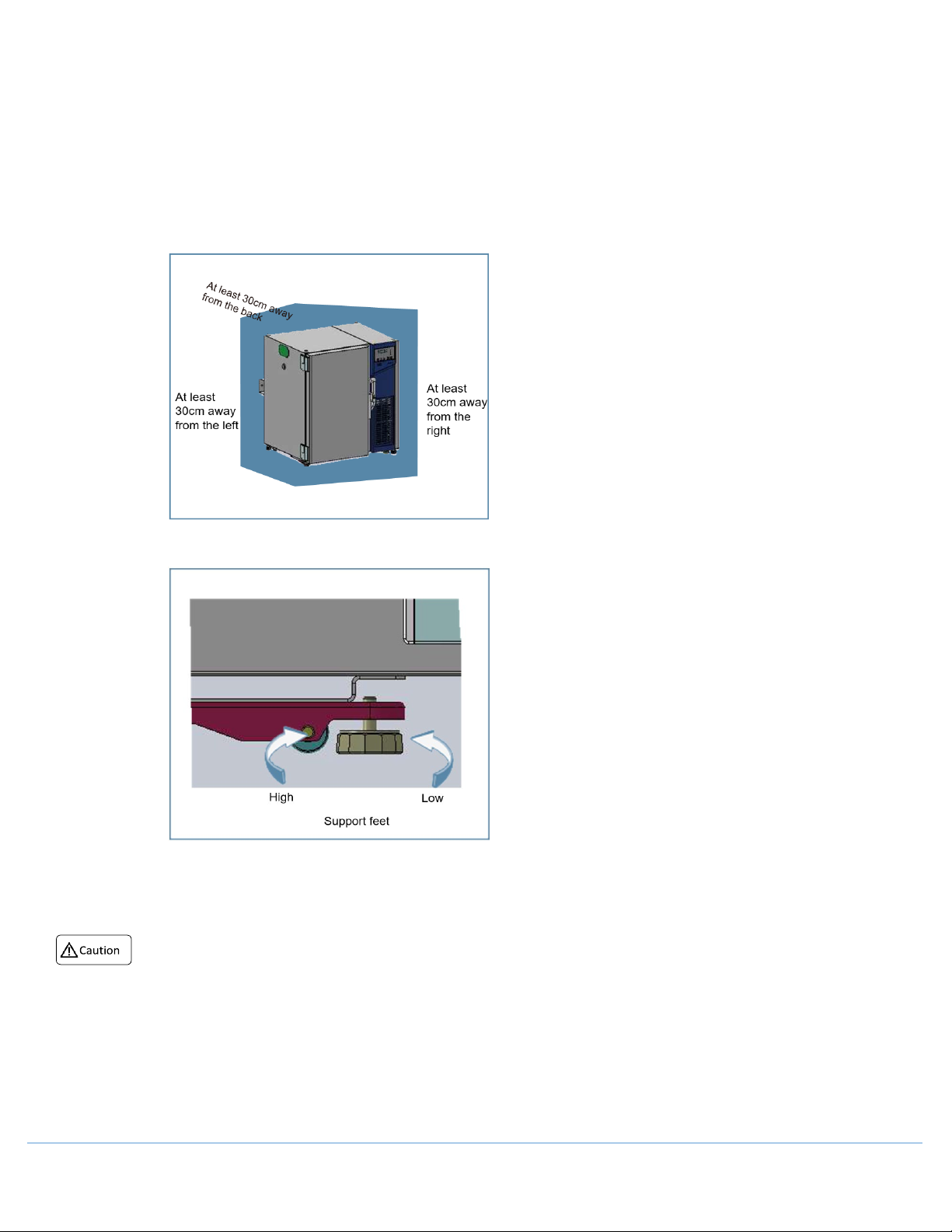
5.2 Installation Site ..................................................................................................................................8
5.3 Preparation Before Use......................................................................................................................9
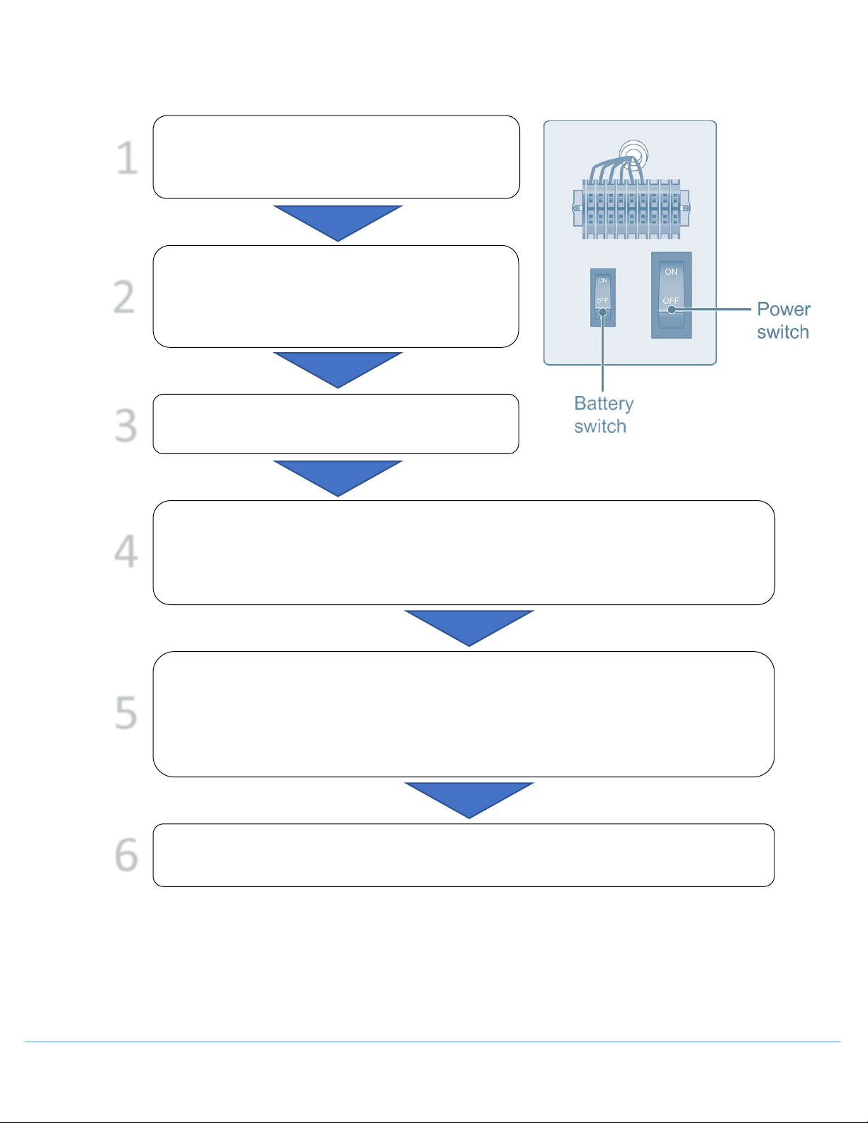
5.4 Initial Startup ...................................................................................................................................10
5.5 Operation after a Power Outage......................................................................................................11
6.0 Refrigerator Components............................................................................................................12
6.1 Control Panel ...................................................................................................................................12
7.0 Operation ...................................................................................................................................13
7.1 Unlocking the Freezer ......................................................................................................................13
7.2 Temperature Setting (TS) .................................................................................................................13
7.3 High Alarm Setting (ALH)..................................................................................................................13
7.4 Low Alarm Setting (ALL) ...................................................................................................................13
7.5 User Parameter Adjustment ............................................................................................................13
7.6 USB Data Export...............................................................................................................................14
7.7 General Setting Notes ......................................................................................................................14
8.0 Display and Alarms .....................................................................................................................15
8.1 Alarm Table......................................................................................................................................16
8.2 Automatic Alarm Recovery Time Setting .........................................................................................17
8.3 Remote Alarm Terminal ...................................................................................................................17
9.0 Cleaning and Maintenance..........................................................................................................17
9.1 Cleaning the Components................................................................................................................17
9.2 Cleaning the Freezer ........................................................................................................................17
9.3 Cleaning the Condenser Filter..........................................................................................................18
9.4 Defrosting the Interior Wall .............................................................................................................18
9.5 Battery Maintenance .......................................................................................................................18
9.6 Freezer Disposal...............................................................................................................................18
10.0 Battery Removal .........................................................................................................................19
10.1 Battery Location...............................................................................................................................19
10.2 Removing the Battery ......................................................................................................................19
11.0 Optional Components .................................................................................................................20
11.1 Storage Shelf and Case.....................................................................................................................20
12.0 Troubleshooting..........................................................................................................................21
13.0 Refrigeration Principle and Circuit Diagram .................................................................................22
13.1 Refrigeration Schematic Diagram ....................................................................................................22
13.2 Circuit Diagram ................................................................................................................................23
14.0 Technical Specifications ..............................................................................................................24
14.1 Specifications ...................................................................................................................................24
14.2 Technical Data..................................................................................................................................24

OM0306 PAGE 3OF 24 REV 1DECEMBER/2020
1.0 Packing List
Item
Quantity
Installation and Commissioning Manual
1
User manual/Position Installation Methods
1/1
Plastic bag
1
Ice scraper
1
Key
4
Position limiter
2
2.0 Precautions for Safe Operation
Thank you for choosing a Nuaire Laboratory Ultra Low Temperature (ULT) Freezer. Please read this manual for
safe operation of this product.
2.1 Safety Labels and Precautions
Complied with the requirements of MDD 93/42/EEC annex V
2.2 Precautions for Safe Operation
When CO2/LN2 backup is activated, the location place must be well ventilated. Increased CO2 in the air may be
harmful and even fatal. If the ventilation is poor, other methods should be considered to ensure safe working
environments.
If there is a leakage of petroleum gas or other flammable gas, close the gas supply valve and open doors and
windows to ventilate the air. Do not plug or unplug your freezer unit to avoid potential explosion or fire.
Warning
Electric
Shock
Combustible
Materials
Low
Temperature
Slippery
Surface
Electrical
Ground
Watch Your
Fingers and
Hands

OM0306 PAGE 4OF 24 REV 1DECEMBER/2020
Only professional technicians or service personnel can install the unit. Failure to do so may cause electric shock or
result in a fire hazard.
The freezer must be securely installed on a firm surface. Uneven mounting may result in the product tipping over
causing injury and/or damage.
Only use the dedicated power supply marked on the product label to avoid fire and electric shock.
If the voltage being used is 10% higher than the rated voltage, a regulator with a capacity of 4000 W or higher
must be installed.
If the power cord needs to be extended, the cross-section of the extended cable must be no less than:
o12 wire gauge and no longer than 10 ft [3 m] for products of 115V~/60Hz to avoid fire or electric shock.
o14 wire gauge and no longer than 9 ft [2.75 m] for products of 220V~240V/50Hz to avoid fire or electric
shock.
Your ULT unit is equipped with a standard three-prong power plug (grounded) complying with the standard three-
prong socket (grounded) rated 10 A. Removal of the ground prong
is prohibited. It must be
securely plugged
into the socket, as a loose plug in the socket may cause fire.
Never install your ULT in an unprotected area. If the unit is exposed to moisture, there is a danger of electric shock.
Your ULT must not be installed in a damp area or an area subjected to water spray. This may reduce the degree
of insulation and thereby cause electrical leakage or electrical shock.
Never directly pour water into the unit. The water may cause electrical shock or short circuit.
Do not place heavy objects on top of the unit, as falling objects may cause injury.
Never use gas lines, water mains, telephone lines or lightning rods as the grounding device for you ULT unit.
Improper grounding may cause electric shock or other danger.
Do not touch any electrical components, switches, or power cord with wet hands. Such action may lead to electric
shock.
When unplugging the power cord from the socket, grip the plug itself and pull it out. Do not pull on the power
cord as this may strip the wires out of the plug creating the risk of electric shock and fire.
Should there be any Malfunction in the equipment, power off the unit and unplug the power cord from the power
supply. Continuous operation in an abnormal condition may result in electric shock and fire.
Do not dismantle, repair, or modify the equipment. Such operations may result in fire or personal injury.
Before any repair and maintenance of the freezer, disconnect the power to avoid electric shock or injury to
personnel.
When repairing and maintaining your freezer, take precautions not to inhale any chemicals or aerosols floating
inside and outside the unit. They may be harmful to your health.
If the unit is not to be in use for a long period of time, make sure the power cord is unplugged.
Deteriorated insulation of the power cord may lead to electric shock or fire.
The freezer needs to be disposed by specialized personnel.
Do not use nay unapproved electrical components with the freezer.
Never store flammable, explosive or volatile materials in the unit, nor use any flammable spray near the unit, as
this may cause an explosion or fire.
Never store corrosive chemicals with acid or alkaline properties in the unit, as this can lead to damage to internal
components of the unit.
Do not use any glass containers with the unit. These containers may crack at low temperatures and cause injury.
Do not climb on top of the unit or place any object on it. Falling equipment may cause injury or property damage.
Do not use any hard objects such as nails and wires in opening or gaps such as air ventilation ports. Accidental
contact between a hard object and a moving part may result in electric shock or injury.
After restarting your unit from a power outage or shutdown, ensure that all settings are correct. Accidental
changes in settings may damage the stored products.
In the event of a power outage and recovery, wait for at least 5 minutes before turning the unit on again to avoid
damage to compressors and refrigeration system.

OM0306 PAGE 5OF 24 REV 1DECEMBER/2020
The air filter for the condenser should be cleaned regularly. A dirty filter could cause a malfunction or the freezer
temperature to rise.
During any repair operations, gloves should be worn to prevent getting injured by sharp edges or corners.
Do not use bare hands to directly handle any stored products. The cold temperature of products and the interior
walls may cause frostbites.
Do not tilt the unit more than 45 degrees when moving it.
When moving the unit, be cautious not to cause injury to personnel or damage the unit. Do not attempt to use
the handle to lift or move the unit to avoid damaging the freezer or injuring personnel.
It is recommended the unit be installed and maintained by a professional to avoid any electrical hazard. The
replacement of any spare parts (battery etc.) shall be conducted by technicians approved by manufacturer.
Keep all ventilation openings in the enclosure or, in the structure for building-in, clear of obstruction.
Do not use mechanical devices or other means to accelerate the defrosting process, other than those
recommended by the manufacturer.
Do not damage the refrigerant circuit.
For equipment which use flammable insulation blowing gases, the instructions shall include information regarding
disposal of the equipment.
The instructions for split-systems that use a flammable refrigerant shall include the substance of the following
warning:
To reduce flammability hazards the installation of this equipment shall only be carried out by a suitably qualified
person.

OM0306 PAGE 6OF 24 REV 1DECEMBER/2020
3.0 Product Features
This product can be used by clinical, pharmaceutical, scientific research, quarantine departments, etc. for the
preservation of articles under low temperature and by blood stations, hospitals, centers for disease control and
prevention, scientific research institutes, electronic chemical engineering and other enterprise laboratories,
biomedical engineering research institutes, ocean fishing companies, etc. for the preservation of red blood cells,
white blood cells, viruses, germs skin, skeletons, bacteria, seminal fluids, biological products, electronic devices,
special materials, etc. under low temperature.
•Temperature control
oTemperature is controlled by computer and numerically displayed and regulated in units of 1°C;
temperature range: -40°C to -86°C (-40°F to -123°F).
•Safety system
oVarious malfunction alarms (high temperature alarm, power failure alarm, probe failure alarm,
hot condenser alarm, high ambient temperature alarm, doors open alarm, low battery alarm).
oTwo types of alarms (Buzzer sounding alarm, Flashing light alarm).
oProtective functions (password protection, power up delay protection).
oAll independent components are safely grounded.
•Refrigeration system
oOptimized auto-cascade refrigeration technology and imported compressor, ensuring stronger
refrigeration capacity.
oHigh-performance insulation layer, ensuring excellent thermal insulation effect.
oUnique multi-layer door sealing structure and anti-condensation heating technology, effectively
reducing frosting.
oScope of application: applies to the preservation of articles by clinical, pharmaceutical, scientific
research, quarantine departments, etc. under low temperature.
o31.875” [810 mm] cabinet, placeable under the laboratory bench, saving the storage space.
•Ergonomic design
oLED display screen, showing temperature inside the box, ambient temperature and input voltage,
settable high/low temperature alarm and temperature inside the box, having fault warning
function.
oAdjustable shelf design, convenient for storage of articles.
oSafety door lock to prevent opening at will.
oWide climate zone design, suitable for the environment ranging from 50°F to 90°F [10°C to 32°C].
o“Innovative” integration of lock and handle and compact caster design, ensuring flexibility and
convenience.
oIntelligent condenser fan start and stop, saving energy effectively.
oAdvanced and practical network and remote warning.
NOTE: Not all models have all features mentioned above. For specific features, refer to the specification table of
each specific model. Due to the product improvement, the Nuaire ULT Freezer you get may not be
completely consistent with the illustration in the manual. The contents of this manual are subject to
changes without notice.

OM0306 PAGE 7OF 24 REV 1DECEMBER/2020
4.0 Usage Precautions
•When the unit operates normally, the unit frame at the front near the door may be slightly warm; This
phenomenon is normal because hot tubing is embedded there to prevent condensation from forming on the
frame.
•Before samples are loaded into the unit, make sure the unit temperature has reached the set point then load
the samples into the freezer in batches. Each batch should not exceed 1/3 of the unit capacity, so that the
temperature does not rise while samples are being loaded.
•The temperature display indicates the temperature from the sensor location inside the unit chamber, which
may vary from the temperature at the center of the freezer but will gradually reach the actual temperature
of the freezer over time.
•Two access ports are installed in the back wall of the unit which can be used as the pass-thru for thermocouple
wires during testing and validation. Once all test wires are through the access port, make sure that the gap in
the port is sealed properly with insulation materials. Failure to seal the access port may affect the operation
of the unit. The port ring in the outer wall can also accumulate frost and ice.
•When cleaning the unit, mild or neutral detergent solution should be used. Never use a hard wire brush, acid,
gasoline, powder detergent, polishing powder, or hot water to clean the freezer, as these tools and materials
can damage the paint coating and plastic components. Never use gasoline or solution with volatile chemicals
to clean plastic or rubber parts.
•After the freezer runs for some time, a layer of frost usually forms on the interior liner and inner doors. When
this layer of frost becomes too thick, it can negatively impact the refrigeration performance of the unit. Energy
consumption can increase. If the thickness reaches about 3/16” [5 mm], use the supplied scraper to remove
the frost.
•Before removing the frost, temporarily transfer the stored samples to another freezer to prevent rising
temperature from damaging the samples.
•Behind the interior walls, there are many refrigeration lines. Do not use a knife, an ice pick, or a screwdriver
to cut ice and frost. This may damage not only the liner but also the refrigeration tubes.
•If the freezer is not in use for an extended period, turn off the power and backup battery. The power cord
should be unplugged.
•Basic performance claimed by the EMC test:
oThe basic performance of the box is that the refrigeration system can work normally.
oThe temperature cooling function inside the box can be achieved.
•Electromagnetic compatibility requirements:
a) This machine complies with the emission and immunity requirements specified in EN 61326-1.
b) This machine is designed and tested as Class A equipment specified in CISPR. In domestic situations, this
machine may cause radio interference and protective measures shall be taken.
c) It is recommended to evaluate the electromagnetic environment before using the machine.
d) It is prohibited to use this machine near strong sources of radiation (such as unshielded video sources),
otherwise it may interfere with normal operation of this machine.

OM0306 PAGE 8OF 24 REV 1DECEMBER/2020
5.0 Product Installation
5.1 Installation Environment
•Ambient temperature: 50°F to 90°F [10°C to 32°C]. The ideal temperature is 65°F to 77°F [18°C to 25°C]. If
necessary, use an air-conditioning system to achieve the requires ambient condition.
•Environment humidity: less than 80% RH. At an environment of 90°F [32°C], humidity should be less than 57%
RH.
•Avoid large amounts of dust.
•Avoid mechanical swing or vibration.
•Highest recommended elevation for safe usage: 6,500 ft [2,000 m] above sea level.
•Input voltage: rated voltage ± 10%.
•The transient state is Category II facility (overvoltage category).
•Pollution Degree: 2
o
An ULT is sensitive to its operating environment. If a unit is not installed in the conditions
mentioned above, it may not operate reliably.
o
The unit is intended for indoor use only.
5.2 Installation Site
For the equipment to achieve optimal operating conditions, an intended installation location should satisfy the
following requirements.
•Do not install the unit in a confined space. The doorway should be large enough for the unit to freely be
transferred in or out of the room if necessary. This is to allow the unit to be repaired easily and timely to avoid
damage to property.
•The location for installation should be flat and firm.
•There should be good ventilation and no direct sunlight.
•The freezer unit cannot share the same power socket with other equipment. The power plug should be
securely connected to the power socket.
•The power cord for the freezer should not be twisted or pinched.
•If the power cord needs to be extended, the cross-section of the extended cable must not be no shorter than
2 mm (14 gauge wire) and no longer than 10 ft [3 m].
•Before using the freezer, check the voltage supply. A voltage stabilizer to deliver rated voltage ± 10% is
recommended for areas in which the voltage is known to be unstable. The voltage stabilizer should be rated
at least 4000W.
•The freezer must be grounded.
•If the power socket is connected with a ground terminal, make sure to inspect it for proper connection before
using the equipment.
o
Do not ground the freezer through gas lines, water mains, telephone lines and lightning rods,
as this may lead to electric shock.
o
After installation, the power plug must be easily accessible to unplug in case of an emergency.
Nothing should block ventilation port of the freezer.

OM0306 PAGE 9OF 24 REV 1DECEMBER/2020
5.3 Preparation Before Use
1. Remove packing material and straps.
2. Check the supplied accessories
•Check the items in the packing box according to the packing list. If anything does not match, contact the
manufacturer.
3. Placement
•This freezer is for indoor and dry conditions only.
•Reserve at least 1 ft [30cm] of clearance on each side of the freezer for proper ventilation.
4. Adjust Levelling Legs
•Rotate the levelling legs clockwise to extend them to level the unit.
5. Acclimation Period
•After adjusting and cleaning the unit, do not turn on the power. The freezer needs to acclimate to its
surroundings for at least 24 hours to ensure proper operation.
oTo handle the freezer before unpacking, forklift or package carrier may be used. If the forklift is used,
it shall be inserted at the bottom of blocking from the front or back of the freezer to move the
freezer. If the package carrier is used, it shall pick up at the bottom of blocking and can only pick up
the side of the freezer.
oAfter unpacking, you may push wheels for maneuvering.
oDuring handling, do not tip the freezer at more than 45° to avoid tipping.

OM0306 PAGE 10 OF 24 REV 1DECEMBER/2020
5.4 Initial Startup
When powering on the unit for the first time, follow the procedures below:
While keeping the unit empty, plug in the power cord
to dedicated power socket that meets all electrical
requirements.
Connect the freezer to the power supply, turn on the
power switch located on the side of the freezer (as in
the illustration on the right), and then turn on the
battery switch.
If the unit has a backup cooling system (optional) turn
off the backup system.
Set the unit to the desired temperature: Do not load the unit with any samples. Power up the
unit to let it run down to -60°C. Let it run at -60°C for 8 hours then lower it to -80°C. Observe
the unit performance for 24 hours for normal cycling to ensure that it is working properly.
Once the unit is confirmed to be operating properly, it is ready to be loaded with samples. In
principle, the freezer unit should be set at about 3°C above the desired temperature. For
example, if the storage temperature is -60°C, set the unit at -57°C. Load the unit with samples
in batches of less than 1/3 of the unit’s capacity. Make sure that the unit is capable of cycling
for more than 8 hours.
If the unit has a backup cooling system (optional), turn it on.
1
2
3
4
5
6

OM0306 PAGE 11 OF 24 REV 1DECEMBER/2020
Your ULT unit should be cared for by trained personnel. Every 2 to 4 hours, the Unit’s working status should be
inspected and recorded daily. Should there be a malfunction in the unit, the freezer temperature rises. If the
problems cannot be corrected in a short time, remove the stored samples, move them to another unit that meets
the temperature requirements to avoid potential damage to samples.
Before putting samples in the freezer to be stored, first check that the freezer’s temperature is at the desired
setpoint to prevent damage or loss.
All ultra-low temperature storage units are low temperature storage equipment.
It is not recommended to load excessive amounts of samples into the unit at one time. Overloading may result
in inadequate performance. The freezer and the compressors can become overheated.
Samples must be loaded in batches, while gradually decreasing temperature setting. The process should be
repeated until the final temperature is reached.
Do not use any unauthorized mechanical tools or other means to accelerate the defrosting process.
Do not damage the refrigeration circuit.
Do not use any unapproved electrical components in the freezer.
5.5 Operation after a Power Outage
Your ULT freezer control settings are stored in its memory system. Should there be power outage and
recovery, the unit can resume its operation based on the previous settings.
oIn the event of a power outage and recovery, be sure to wait for at least 5 minutes before turning the unit
on again to avoid damaging the compressors and refrigeration system.
oIf the unit is not in use for a long period of time, make sure the power cord is unplugged. Deteriorated
insulation of the power cord may lead to electric shock or fire.

OM0306 PAGE 12 OF 24 REV 1DECEMBER/2020
6.0 Refrigerator Components
6.1 Control Panel
Outer Door
Support Feet
Condenser Filter Grill
Door Handle
W/ Lock
Control Panel

OM0306 PAGE 13 OF 24 REV 1DECEMBER/2020
7.0 Operation
7.1 Unlocking the Freezer
1. Press “Up” to “06”
2. Press and hold “Set” for 5 seconds to make “Locked” light off to enter unlock state and carry out various
settings
3. Press “Set” to select “TS” (temperature setting inside the box), “ALH” (high-temperature alarm setting), and
“ALL” (low-temperature alarm setting) in a circular manner
7.2 Temperature Setting (TS)
1. Under the unlock state, press “Set” to select the “TS” and make current set temperature inside the box flash
2. Press “Up” or “Down” to adjust the set temperature inside the box
3. After completion of modification, press “Set” to save set temperature inside the box and return to display TS
7.3 High Alarm Setting (ALH)
1. Under the unlock state, press “Set” to select the “ALH” setting and make current set ALH value flash
2. Press “Up” or “Down” to adjust the set ALH value
The modification scope shall be set temperature inside the box + 5°C ~ 0°C
3. After completion of modification, press “Set” to save set ALH value and return to display ALH
NOTE: If there is no key operation for 20 seconds, the set ALH value is not saved, and after function lock, the
temperature inside the box is displayed.
7.4 Low Alarm Setting (ALL)
1. Under the unlock state, press “Set” to select the “ALL” setting and make current set ALL value flash
2. Press “Up” or “Down” to adjust the set ALL value
The modification scope shall be -99°C ~ set temperature inside the box - 5°C
3. After completion of modification, press “Set” to save set ALL value and return to display ALL
NOTE: If there is no key operation for 20 seconds, the set ALL value is not saved, and after function lock, the
temperature inside the box is displayed.
NOTE: ALH and ALL values are related to the TS values. If the temperature inside the box is changed, the
difference of ALH and ALL values from temperature inside the box shall not change. If ALH and ALL values
are changed, temperature inside the box shall not be changed.
7.5 User Parameter Adjustment
Under the unlock state, press and hold “UP” for 5s to enter the user parameter settings, and press “UP or “Down”
to select 7 parameters including dA, T1, T2, P6, IC, PS1 and CL1. Press “Set” after selecting one parameter to
modify this parameter.
1. dA: door opening alarm delay, with default of 5min, adjustable from 1 to 30min
Press "Up" or "Down" key to modify the set value of door-opening alarm delay
2. T1: The USB fetch cycle defaults to 6min, which is adjustable in 1 ~ 99min
Press "Up" or "Down" key to modify the set value of usb fetch cycle
3. T2: USB time, Year (P1:10 to 99) / Month (P2:01 to 12)/Day (P3:01 to 31)/Hour (P4:00 to 23)/ Minute (P5:00
to 59)
Press “UP or “Down” to modify the set usb time.

OM0306 PAGE 14 OF 24 REV 1DECEMBER/2020
4. P6: USB derivative mode, with the default of 12, adjustable from 0 to 12
The data can be exported in different periods, the parameters 0 ~12 can be set, and the default value of 12
means the one year of data can be exported once; setting it to 0 means exporting all the data once, setting it
to be 1 - 12 means respectively exporting the data of several months before the current time, such as the data
of 2 months, 3 months... 12 months.
Press “UP or “Down” to modify the set USB derivative mode value
5. IC (optional): IC card registration password modification, with the default of 008, adjustable from 000 to 999
Press “UP or “Down” to modify the set IC card registration password.
Setting method: Press "Up" or "Down" key to increase or decrease the password value by 1. Press "UP" or
"Down" for each 1s to increase or decrease by 1. When continuously increasing or decreasing by 10, press
“UP" or "Down" to for each 1s to increase or decrease by 10.
6. PS1: unlock password, with the default of 06, adjustable from 01 to 99; Press "UP" or "Down" to modify the
set unlock password value.
Setting method: Press "Up" or "Down" key to increase or decrease the password value by 1. Press "UP" or
"Down" for each 1s to increase or decrease by 1. When continuously increasing or decreasing by 10, press
"UP" or "Down" to for each 1s to increase or decrease by 10.
7. CL1: IC card logout, with the default of 0, adjustable from 0 to 1.
Select CL1 for parameter list. Press “Set”, 000 flashes and it requires to enter the registration password. Enter
the correct password and then press “Set” to execute the order. The CL1 flashes for 3 times and there is a
buzz sound, which means that the logout is completed. In case of three times of entering wrong password, it
will exit and lock, and re-display the temperature inside the freezer.
7.6 USB Data Export
1. Plug in the USB disk to automatically export the temperature, alarm, and event records of the machine. When
the data export is started, the decimal point in the lower right corner of the display panel flashes. When the
data export is completed, the decimal point is solid. Unplug the USB disk and the decimal point is off.
2. System storage space can meet 15 years of data storage.
7.7 General Setting Notes
1. The "Set" key must be pressed for confirming the saving after each parameter value is set. In other cases, the
modified value cannot be saved.
2. In the above parameter setting process, press the "Silence" to return the last layer of parameter/exit the
parameter setting, or exit the parameter setting with 20s of no pressing.

OM0306 PAGE 15 OF 24 REV 1DECEMBER/2020
8.0 Display and Alarms
Connect the power supply for the box and switch the power switch to the “ON” position to enter power-on state
and make the display screen to show the temperature inside the box.
Working status prompt of the display panel:
“Locked” light on: all settings are locked to prevent accidental operation; “Run” light on: the refrigeration system
is in operation;
“Power” light on: the box has been powered by the main power supply; “Alarm” light on: the box has a fault alarm.
Functions of the buttons:
•“Set”: enter the unlock password to unlock the keyboard (long press for 5s) or confirm the settings.
•“Up” and “Down”: select parameters or increase / decrease parameter values and can be cycled when used
for selecting parameters or parameter values.
•“Silence”: temporarily silence the buzz or return to the previous-level parameters / exit parameters setting to
return to display the temperature inside the box.
•“Inquiry”: when the display panel is locked, press this key to query the device alarm code, input voltage and
the ambient temperature where the equipment is used. The digital display shows the corresponding fault
code, voltage, and ambient temperature for 2s and then restores to display the temperature inside the box.

OM0306 PAGE 16 OF 24 REV 1DECEMBER/2020
8.1 Alarm Table
Alarm
Code
Status
Indication
Buzzer
High Temperature
Alarm E00
Displayed temperature ≥ set
temperature for high-temperature
alarm, continuously for 1min
Alarm light flashes and
overtemperature alarm
light flashes
Buzzer alarm, remote alarm
output
Low Temperature
Alarm E01
Displayed temperature ≤ set
temperature for low-temperature
alarm, continuously for 1min
Alarm light flashes and
overtemperature alarm
light flashes
Buzzer alarm, remote alarm
output
Too High Ambient
Temperature
E02
Ambient temperature ≥ 35
℃
,
continuously for 30s
Alarm light flickers /
Main Sensor Fault
E10
In the case of main sensor fault
Alarm light flickers
Buzzer alarm
Fault of the Ambient
Temperature Sensor E11
In the case of ambient
temperature sensor fault Alarm light flickers Buzzer alarm
Condenser Sensor
Fault E12 In the case of condenser sensor
fault Alarm light flickers Buzzer alarm
Battery
Disconnection
E20
Power switch turning off or
battery connection line loosening
Alarm light flickers Buzzer alarm
Reversed Battery
Installation
E21
Detect that the reversed battery
installation signal is low level
Alarm light flickers Long buzzer sound alarm
Low Battery
E22
Lead-acid battery: when the
battery is connected, after the
battery is charged for 24 hours,
the battery voltage is less than
10.5V
Alarm light flickers
/
Lithium battery: when the
battery is connected, after the
battery is charged for 24 hours,
the battery voltage is less than
9.0V
Alarm light flickers
/
Power Failure Alarm
E30
When the box is powered off
Alarm light and power
indicator flash
simultaneously
The buzz alarm sounds once
every 3 seconds; the display
panel does not display the
temperature inside the box
for 30 seconds; the normal
display lasts for 5 seconds;
the above-mentioned
displays occur alternately;
remote alarm output
Door Opening Alarm
E40
The door opening signal is
detected for 5 minutes
Alarm light flickers
Buzzer alarm, remote alarm
output
Dirty Condenser
Fault
E50
When the condenser filter is
blocked, or the condenser
temperature is too high due to the
high ambient temperature
Alarm light flickers
Buzzer alarm
•A flashing alarm cannot be cancelled unless the malfunction is eliminated. The buzzing alarm can be temporarily
silenced for 30 minutes by pressing the “Silence” key. However, if the problem persists, the buzzer alarm will resume
after 30 minutes.
•When using the freezer, the battery switch must be turned on to charge the battery.
•When there is a power outage, the battery sustains the temperature display. If the battery voltage is insufficient, the
temperature display will turn off.
•While the battery is still capable of providing power to display, the temperature display can be turned off by
unplugging the power cord and turning off the battery control switch.

OM0306 PAGE 17 OF 24 REV 1DECEMBER/2020
8.2 Automatic Alarm Recovery Time Setting
•When the unit is in alarm mode, you may press the “Silence” key to stop the buzzing of the alarm. (The remote
alarm cannot be cancelled).
•If the condition persists, the buzzer alarm will resume automatically after 30 minutes.
8.3 Remote Alarm Terminal
•The remote alarm terminal is installed on the right side of the freezer's
engine cabin, and the alarm signal will be output by this terminal. The load
capacity of the terminal is DC 30V, 2A.
•Contact output: The remote alarm terminal is divided into: Normally open,
normally closed, common terminal.
•Standard RS485 port can be used to transmit freezer temperature data to
customer’s software for monitoring.
9.0 Cleaning and Maintenance
9.1 Cleaning the Components
•To prevent electric shock or injury to operators, the AC power supply to the freezer must be disconnected
completely prior to any repair and maintenance work is being performed.
•During any repair maintenance work, do not inhale sample particles or aerosols near the equipment as
this may harmful.
9.2 Cleaning the Freezer
•Clean the unit once a month.
•Use a dry cloth to wipe away loose dust inside and outside of the freezer. If the unit is dirty, use a clean
cloth soaked with a neutral detergent solution.
•Using a dry cloth to wipe away any residual detergent solution.
•Do not pour water directly onto the exterior or into the interior of the unit. Water can damage the
electrical insulation thereby causing a malfunction.
•Compressors and other mechanical parts are hermetically sealed. They do not need lubrication.
•Clean frost and ice off the unit once a month.
•Clean the condenser filter once a month.

OM0306 PAGE 18 OF 24 REV 1DECEMBER/2020
9.3 Cleaning the Condenser Filter
When the cooler panel shows an alarm signal for “Hot Condenser”, the alarm light flashes. The filter should be
cleaned once a month. If the filter is clogged, it will affect the refrigeration efficiency and reduce the product’s
lifespan.
To clean the filter, follow the procedure below:
1. Remove the front grill cover.
2. Pull out the filter screen.
3. Use water to wash the filter screen.
4. After the filter screen is dry, reinstall It back in its original
position and close the cover.
5. If the “hot Condenser” light is on before cleaning, check the light
to make sure that it shuts off after cleaning.
If it does not shut off, contact service personnel at Nuaire.
9.4 Defrosting the Interior Wall
Frost and ice can form between the door gasket and frame to form an air gap, which can decrease the refrigeration
effect of the unit. Use the provided plastic scraper to remove excess frost.
To defrost the unit, follow procedure below:
1. Turn off any backup refrigeration system if applicable.
2. Remove the samples from the unit that need to be defrosted. Move them to another unit or a container for
temporary storage.
3. Turn off the power supply.
4. Open the outer door and inner doors to let the unit thaw.
5. Use a dry cloth to soak up any water on the floor of the unit before restarting the unit.
6. Load the samples back into the unit after it reaches the set temperature.
7. Turn on the backup refrigeration system if present.
Do not remove the frost by knife, screwdriver, or other sharp tools.
9.5 Battery Maintenance
•During continuous power-on operation of the box, check the battery level every 15 days. If low battery level
is detected, ensure that the battery switch is in the “ON” position to make the battery charged. When charging
the battery for one week continuously, re-test the battery level. Under normal circumstances, the battery
should be sufficient at this time. If the battery level is still low, it is recommended to replace the rechargeable
battery.
•The battery is a kind of consumables and its service life is about 2 to 3 years. If the battery has been used for
more than 3 years, it may fail to give an alarm in case of power failure.
9.6 Freezer Disposal
•If the unit is left unused for a long time in an unsupervised area, ensure the unit is secured to prevent any
unauthorized access.
•Scrapping of the unit should be carried out by professional personnel. Be sure to dismantle the door to
prevent any accidents.

OM0306 PAGE 19 OF 24 REV 1DECEMBER/2020
10.0 Battery Removal
10.1 Battery Location
The battery is for the power outage alarm. It is located inside the control box on the right side of the unit.
There are high voltage components in the control box. To prevent electric shock, only a qualified technician
or engineer should open the cover.
10.2 Removing the Battery
1. Turn off the unit and unplug the power cord from the socket.
2. Remove side panel by removing screws.
3. Use a screwdriver to remove the 4 screws on the cover of the control box.
4. Unplug the connecting terminals from battery.
5. Remove the bracket that fastens the battery. Then remove the battery.
6. Follow regulations to recycle or properly dispose of battery.
When changing the battery, make sure that the brown wire connects to the positive pole of the battery and
that the blue wire connects to the negative pole of the battery.
The polarity must not be reversed. Incorrect polarity can damage the computer’s motherboard and prevent
the battery from being charged.
Connect the brown wire to the
positive (+) terminal of the battery
Connect the blue wire to the
negative (-) terminal of the battery

OM0306 PAGE 20 OF 24 REV 1DECEMBER/2020
11.0 Optional Components
11.1 Storage Shelf and Case
If the unit is used to store small samples, storage racks and boxes provide more efficient use of internal space.
Model
Storage Rack (A/B, optional)
Storage box
Configuration
Quantity
Quantity
NU-99100J
5x3
4
60
This manual suits for next models
2
Table of contents
Other NuAire Freezer manuals
Popular Freezer manuals by other brands

Kenmore
Kenmore 253 Series owner's manual

montpellier
montpellier MTF273X Installation and operating instructions

Exquisit
Exquisit KOELKAST KS 15-4 A++ User instruction

VOX electronics
VOX electronics VF-2500 operating instructions

KRAFT
KRAFT KF-HS200WSF user guide

Frigidaire
Frigidaire FFC18C4CW Factory parts catalog