NuAire BLIZZARD NU-99729VFT User manual

OM0300
Series A
Revision 2
April 2022
NuAire, Inc.
2100 Fernbrook Lane
Plymouth, MN 55447
Toll-Free: 1-800-328-3352
Minnesota: (763) 553-1270
Fax: (763) 553-0459
NUAIRE BLIZZARD ULTRA LOW TEMPERATURE
VARIABLE FREQUENCY TOUCHSCREEN FREEZER
NU-99729VFT
SERVICE MANUAL

OM0300 PAGE 2OF 42 REV 2APRIL/2022
Table of Contents
1.0 Features of the Product................................................................................................................ 3
1.1 Main Functions and Features of the Product ..................................................................................... 3
2.0 Product Details ............................................................................................................................ 3
2.1 Temperature Control .......................................................................................................................... 3
2.2 Safety Control ..................................................................................................................................... 3
2.3 Refrigeration system........................................................................................................................... 3
2.4 Practical design ................................................................................................................................... 4
2.5 VIP ....................................................................................................................................................... 4
2.6 Temperature monitoring function...................................................................................................... 4
2.7 Noise ................................................................................................................................................... 4
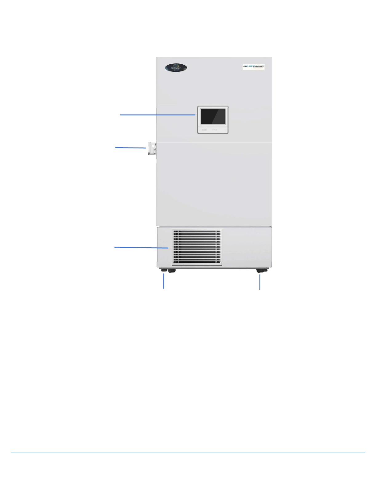
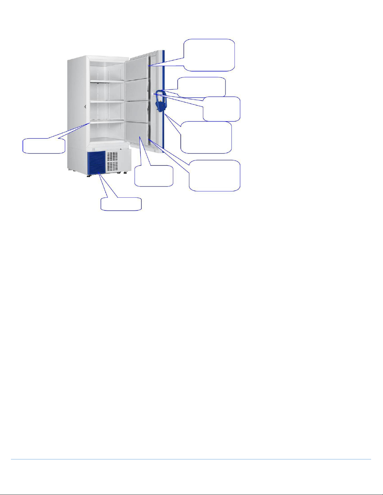
3.0 Parts of the Freezer...................................................................................................................... 5
3.1 Freezer Overview ................................................................................................................................ 5
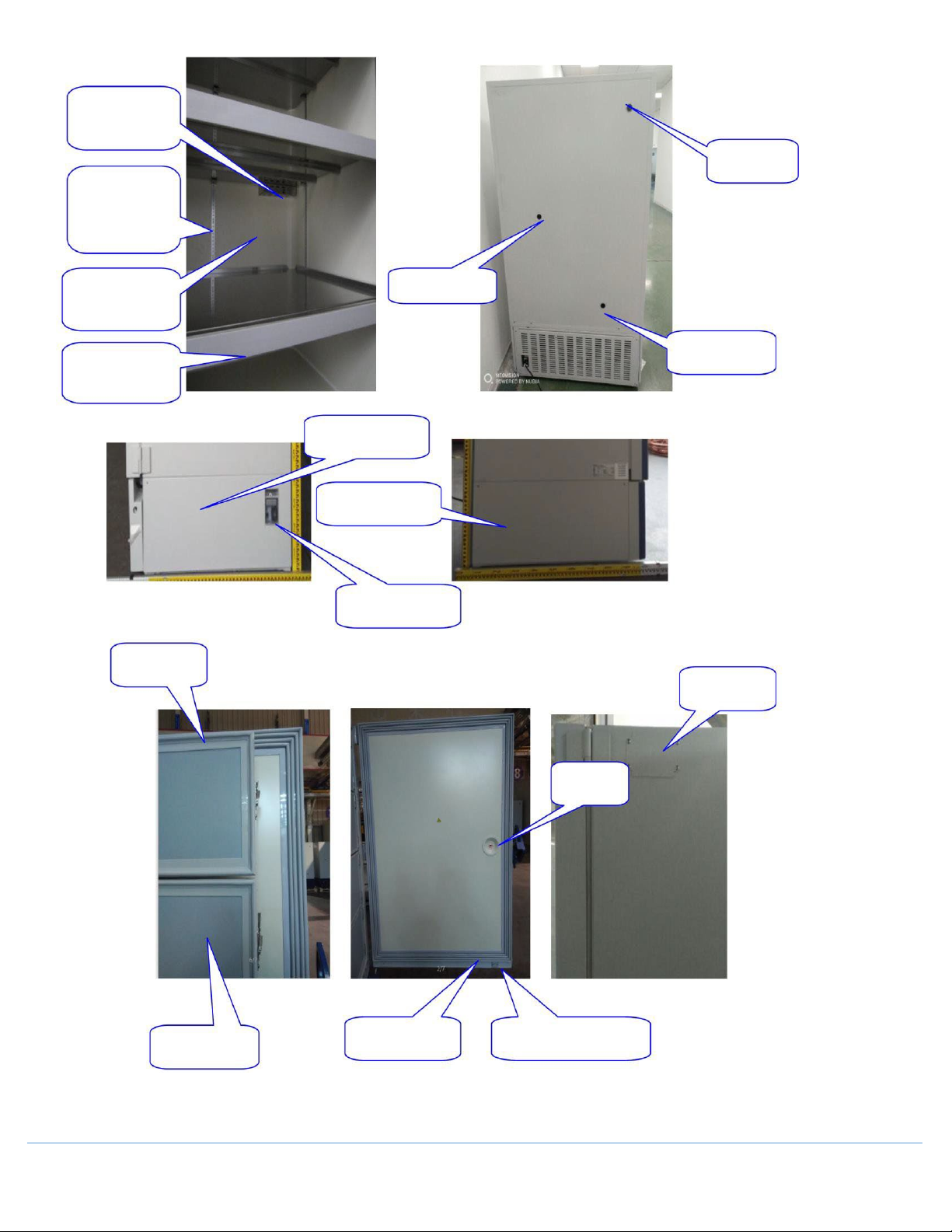
3.2 Inner Door Components ..................................................................................................................... 6
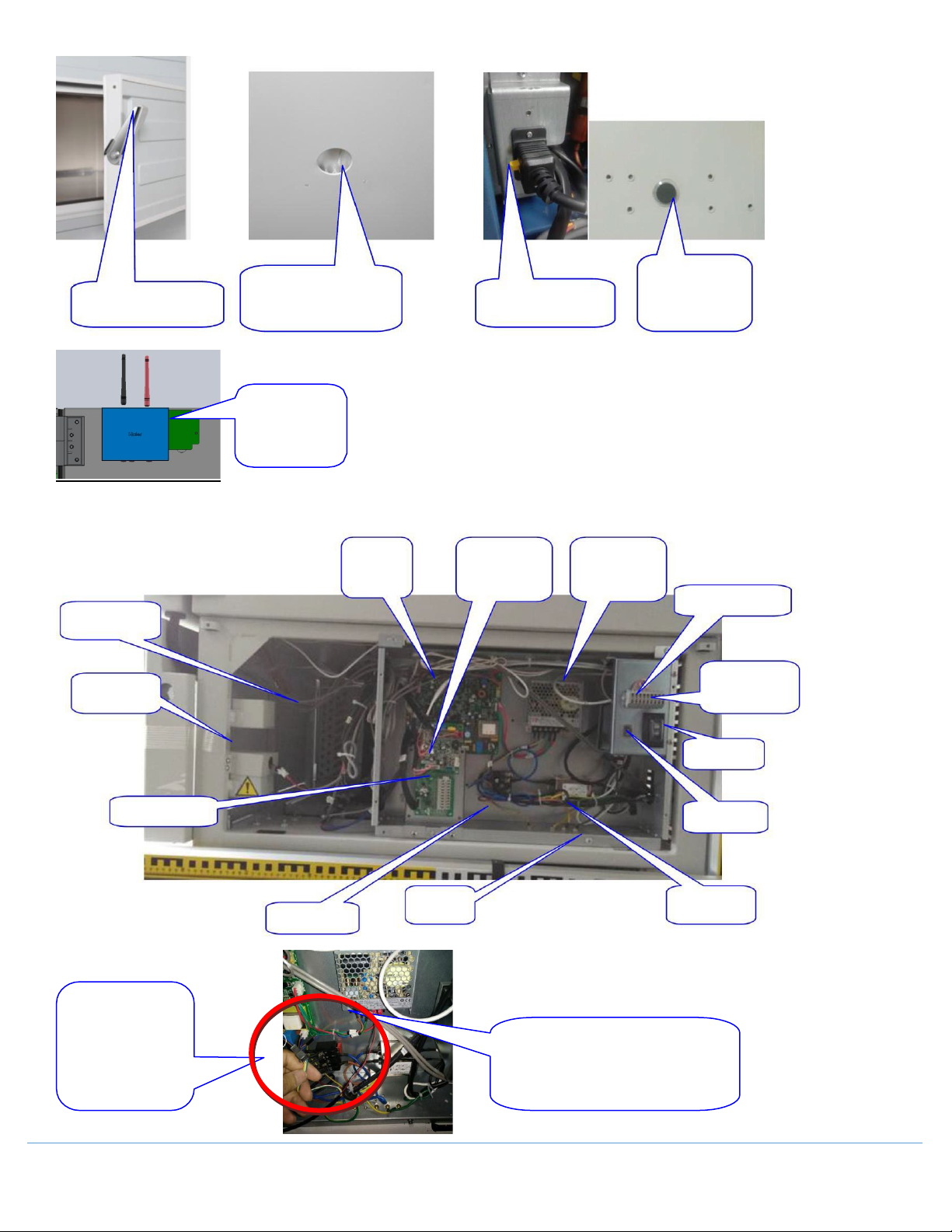
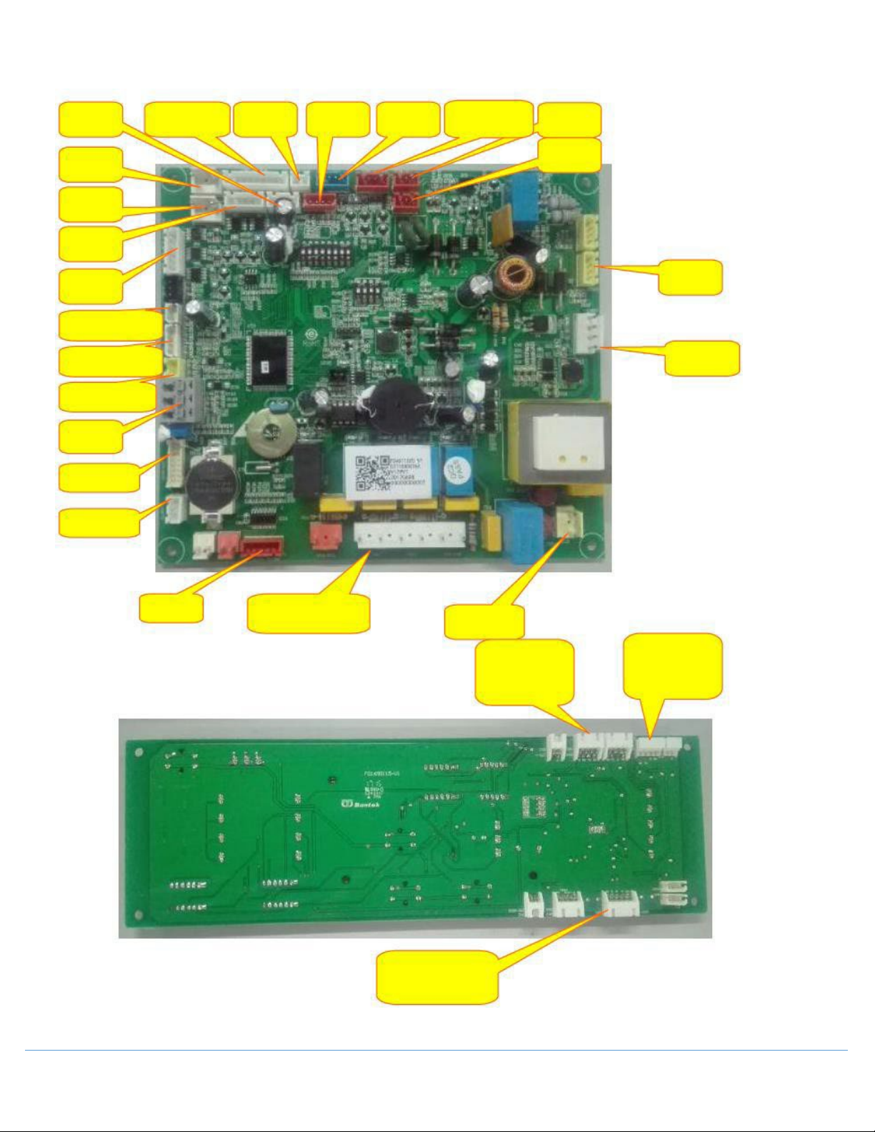
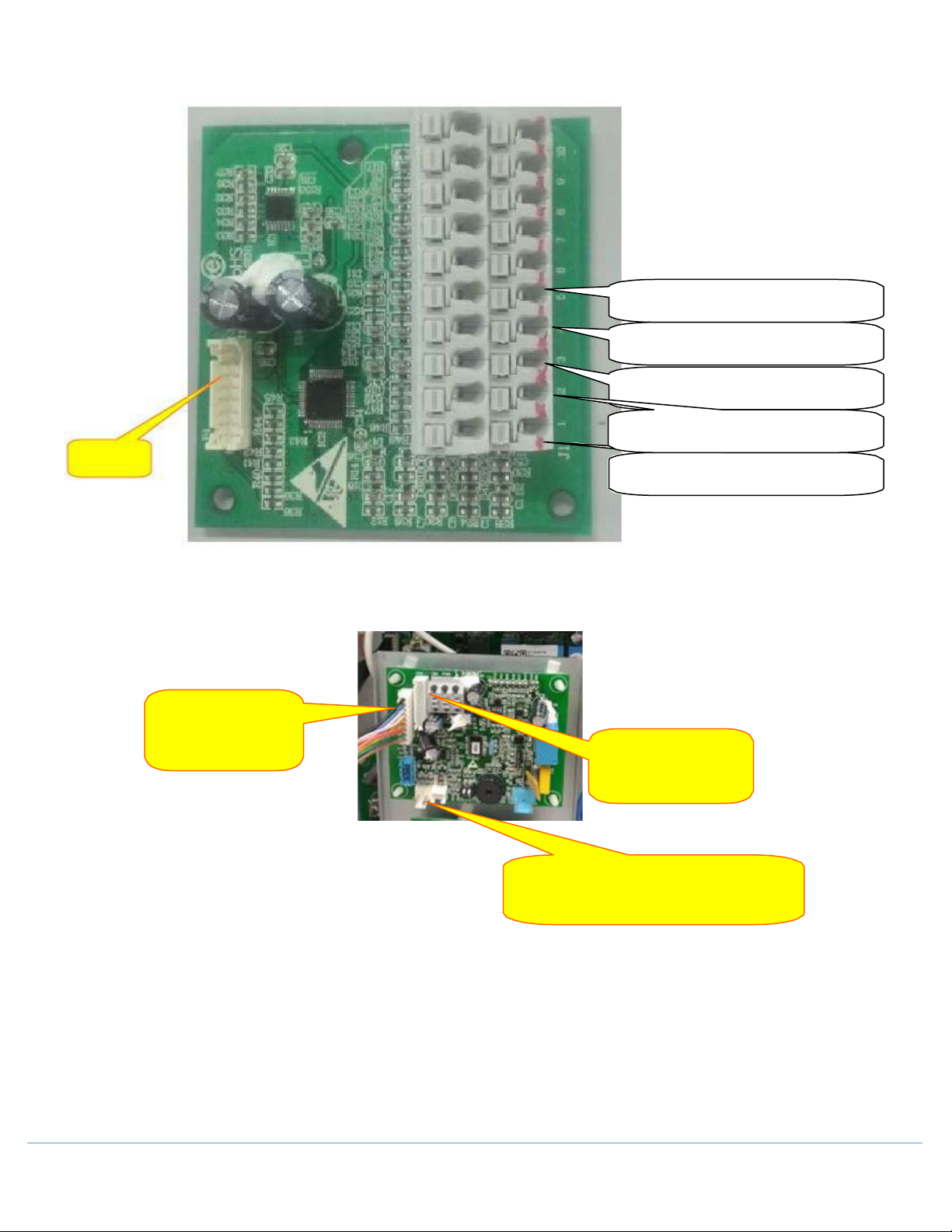
3.3 Electrical Components ........................................................................................................................ 8
3.4 System Structure............................................................................................................................... 12
4.0 Process Overview........................................................................................................................14
4.1 Administrator Permission ................................................................................................................. 14
4.2 Precautions ....................................................................................................................................... 19
5.0 Technical Parameters..................................................................................................................20
6.0 Preventive Measures, Product Use and Daily Maintenance ..........................................................21
6.1 Principle of Ultra-Low Temperature Frequency Conversion Refrigeration ...................................... 21
6.2 Use Method of Ultra-Low Temperature Cabinet .............................................................................. 21
6.3 Working Principle of Pressure Switch ............................................................................................... 22
6.4 Characteristics of Refrigerant ........................................................................................................... 22
6.5 Filling Process of Refrigerant ............................................................................................................ 22
7.0 Refrigeration Schematic and Wiring Diagram...............................................................................25
7.1 Refrigeration Diagram....................................................................................................................... 25
7.2 Wiring Diagram ................................................................................................................................. 26
8.0 Control System ...........................................................................................................................27
8.1 Control of Compressor...................................................................................................................... 27
8.2 Control of Fans.................................................................................................................................. 29
8.3 Battery Control.................................................................................................................................. 29
8.4 Heating Wire Control ........................................................................................................................ 31
8.5 USB Data Download .......................................................................................................................... 31
8.6 Remote Alarm Function .................................................................................................................... 31
9.0 Installation and Disassembly Process...........................................................................................32
9.1 Installation Location.......................................................................................................................... 32
9.2 Handling and Removal of Packaging Materials................................................................................. 32
9.3 Moving the Unit ................................................................................................................................ 33
9.4 Removal of Display Cover ................................................................................................................. 34
10.0 Troubleshooting and Frequently Asked Questions .......................................................................35
10.1 Problems and Possible Solutions ...................................................................................................... 35
10.2 Troubleshooting Table ...................................................................................................................... 36
10.3 High Alarm Processing Method ........................................................................................................ 39
10.4 Low Alarm Processing Method ......................................................................................................... 40
11.0 Diagram and Spare Parts List .......................................................................................................41

OM0300 PAGE 3OF 42 REV 2APRIL/2022
1.0 Features of the Product
1.1 Main Functions and Features of the Product
1. The application range of the ultra-low temperature cabinet is -40℃to -86℃.
2. The freezer is designed to balance the internal and external pressure of the cabinet, allowing ease of opening
and closing the door.
3. The Microprocessor, 10-inch LCD screen, and the digital display screen can simultaneously display the
temperature inside the cabinet, the setting temperature, the ambient temperature, and the input voltage.
4. Users can set high and low temperature alarm, temperature inside the cabinet, ambient temperature alarm,
user login, inquiry and download data of temperature curve, event record, alarm record, and running status.
5. Multiple fault alarms (high and low temperature alarm, sensor alarm, condenser dirty alarm, excess ambient
temperature alarm, door opening alarm, low battery power alarm, power outage alarm).
6. Two alarm modes (beep alarm, light flashing alarm) and start-up delay protection (start-up delay time can be set
by user's requirement).
7. Network functionality as well as an RS-485 data interface to connect to a computer to display the temperature
inside the cabinet and the alarm information through the computer, and can control the temperature and
monitor whether the equipment is normal.
8. 5V power supply output function, which allows the user to directly supply power to the cold chain module.
9. Remote alarm functions and can connect the alarm to other rooms.
10. The standard USB data storage module supplied with the product can store high and low temperature set, actual
temperature, ambient temperature, and voltage inside the cabinet for more than 10 years.
11. The freezer is supplied with 2 standard 25.5mm test ports.
12. Equipped with casters which are flexible, movable, lockable, supported, and can be adjusted as required.
13. Available options include: a chart recorder, network monitoring system, electromagnetic lock, card punching
module.
14. The LCD screen comes with Wi-Fi module and can connect wireless network to entry sample library function
(optional) to manage sample easily.
2.0 Product Details
2.1 Temperature Control
Computer controlled, temperature digital display, regulating unit of 0.1 ℃, and the application temperature
range of -40 to -86 ℃.
2.2 Safety Control
1. Multiple fault alarms (high and low temperature alarm, sensor alarm, condenser dirty alarm, excess ambient
temperature alarm, door opening alarm, low battery power alarm, power outage alarm).
2. Two alarm modes (buzzing alarm, light flashing alarm and prompt box alarm), start-up delay protection (start-up
delay time can be set by user's requirement).
3. All independent components have safe grounding.
2.3 Refrigeration system
1. Intelligent frequency conversion cascade refrigeration technology, imported brand compressor, strong
refrigerating capacity, environment-friendly refrigerant, no fluorine, zero emission.
2. High-density insulated combined cabinet body design, made of VIP special thermal insulation material, with
good thermal insulation effect.

OM0300 PAGE 4OF 42 REV 2APRIL/2022
3. Independent multi-layer sealing structure and thermal insulation system design, which can effectively eliminate
frosting phenomenon.
4. Specially designed computer control, which can automatically select the optimal compressor start-stop scheme
according to the set temperature and the use environment to reduce the noise and improve the efficiency.
2.4 Practical design
1. LCD display screen, which can display the temperature inside the cabinet, set temperature, ambient
temperature, input voltage, can set high and low temperature alarm and the temperature inside the cabinet,
and have the function of fault prompt and early warning.
2. Adjustable shelf design to facilitate access of goods.
3. Safety door lock, designed with double locks (one padlock and one key built-in lock), to prevent the opening
without permission.
4. Integrated innovative handle design and compact caster design, flexible and convenient.
5. With the function of network and remote alarm, advanced and practical.
6. Unique 5V power supply module, which solves the user's trouble in pulling-down the power supply separately
and is directly powered by 5V output of the whole machine.
2.5 VIP
PU foaming layer + VIP vacuum thermal insulation material is adopted, which reduces the floor area of
equipment to the maximum extent at the time of thermal insulation.
2.6 Temperature monitoring function
1. The alarm information of the equipment can be sent to the registered mobile phone users in the form of short
messages.
2. The actual operating temperature inside the cabinet can be downloaded through the USB data storage module;
2.7 Noise
Unique intelligent compressor start-stop control, enabling lower noise, leading in the world and comfortable
working environment.

OM0300 PAGE 5OF 42 REV 2APRIL/2022
3.0 Parts of the Freezer
3.1 Freezer Overview
LCD Touchscreen
Door Handle
(With Lock)
Component
Access Panel
Leveling Leg
Caster

OM0300 PAGE 6OF 42 REV 2APRIL/2022
3.2 Inner Door Components
Inner door handle: When
replacing, remove the side
screws of the handle.
Outer door handle
Balance valve
Integrated cabinet
opening
Sealing strip of outer
door: take
out from the
retaining groove when
replacing.
Inner door: PU
foaming structure
Sealing strip of inner
door: take out from the
retaining groove when
replacing.
Air-inlet grill

OM0300 PAGE 7OF 42 REV 2APRIL/2022
Fixed cover for main
internal temp.
sensor.
Mounting clip for
stainless-steel shelf.
Zinc-coated inner
liner.
Trim strip of cabinet
shelf.
Back threaded
hole
Test port 1
Test port 2
Engine compartment
guard plate, right side
Power switch cover
plate
Inner door
gasket seal
5V cold chain
Pressure
balancer
Foam core inner
door.
Outer door gasket
seal
Magnetic open door alarm
switch box
Engine compartment
guard plate, left side

OM0300 PAGE 8OF 42 REV 2APRIL/2022
3.3 Electrical Components
Inner door handle
Threaded hole at back of cabinet
body, four-way structure
Test port
Power cord plug
loT module
Main control
panel
Backup system
board
Switching power
supply
Remote alarm wiring
Condenser fan
Lithium battery
485 communication
module port
Power switch
Thermocouple plate
Battery switch
Electric control
box
Filter
Line bank
Signal wire of loT
module, connected to
signal wire terminal of
control board
Power supply cable of IOT module,
connected with switching power supply, red
wire connect with +V, black wire connect
with -V

OM0300 PAGE 9OF 42 REV 2APRIL/2022
Main Control Panel
5V cold
chain
Backup system
Electro-
magnetic lock
Electro-
magnetic lock
Display
panel
Balancing
hole
Condenser sensor
Condenser sensor
Ambient temp.
sensor
Master
sensor
Remote alarm
Loading
plate
Fan/heating wire at
cabinet opening
Strong electric
power supply
CN2:
Punch-card board
CN5:
USB driven board
Switching
power supply
Battery
Networking
Networking
Variable frequency
signal line
3-color
lamp
Printer
Door
switch
Thermocouple
plate
CN1:
Display panel signal line
connector
Display Panel

OM0300 PAGE 10 OF 42 REV 2APRIL/2022
Thermocouple Board
exit of low stage evaporator
entrance of low stage evaporator
exit of low stage condenser
exit of high stage condenser
Main control
panel
entrance of high stage condenser
Connect Main board
Main sensor
Backup system power supply line(option)

OM0300 PAGE 11 OF 42 REV 2APRIL/2022
The antenna
Tricolor board
The main control board and
the HUB board connecting line
Screen control line
Screen control line
HUB board
Main control board
USB line,connect CN5
USB board
Fingerprint Line
(optional)
Fingerprint
module (Optional)
Card reading board
Connect CN2
Speaker

OM0300 PAGE 12 OF 42 REV 2APRIL/2022
3.4 System Structure
Blowing fan
High temperature
compressor
Condensate fan
Low temperature
compressor
Oil separator
Condenser
Condensate Fan
Condenser Sensor
Low Pressure Switch
Low Temperature Drying
Filter
Oil Separator
High Temperature
Drying Filter

OM0300 PAGE 13 OF 42 REV 2APRIL/2022
4 wide-voltage
condensate fan
Oil Separator
High temperature
Low temperature
re
inverter
Low-temperature
inverter
re
油分
e
inverter
The long line of frequency converter signal line connects to the
low-temperature frequency converter, with the short-line
connected to high-temperature frequency converter

OM0300 PAGE 14 OF 42 REV 2APRIL/2022
4.0 Process Overview
4.1 Administrator Permission
Entry method: press “login”, input password 8888888888 to enter the administrator interface.
Connect the thermocouple sensor to the corresponding position on thermocouple board in electrical box,
①Suction line of high stage compressor: corresponding position is No.1 on thermocouple board, it states
temperature of this thermocouple sensor, help to look up cause when fault repair.
①-⑤is for frequency conversion models
⑦-⑧is for dual system models.
[Sensors of History]
Input start time and end time, press “inquiry” to view temperature record of all sensors in this period time;
press “download” to download temperature data. If press download without inputting time period, it will
download temperature data for all time period.

OM0300 PAGE 15 OF 42 REV 2APRIL/2022
[Setting Records]
Input start time and end time, press “inquiry” to view setting records in this period time, press “download” to
download setting record data. If press download without inputting time period, it will download setting record
data for all time period.
[Setting]
Model: the model information for this unit, system self-determination
Temperature calibration of tank: when real measured temperature of tank deviates from temperature
displayed on display panel, calibrate sensor temperature of tank, default value is 0, adjust range is -10℃ ~ 10℃,
displayed temperature doesn’t change after calibration. Example : -80℃is displayed on the machine, but the
user measures that the temperature in the freezer is just -78℃, In order to lessen the difference, the
temperature deviation can be adjusted by +2℃. Thus, the -78℃is displayed.
Calibration of ambient temp: when displayed ambient temperature deviates from real measured ambient
temperature, calibrate the display panel value, default value is 0, adjust range is -10℃~10℃, displayed ambient
temperature changes after calibration. Example : 30℃is displayed on the machine, but the user measures that
the ambient temperature is 35℃, In order to lessen the difference, the temperature deviation can be adjusted
by +5℃. Thus, the 35℃is displayed.

OM0300 PAGE 16 OF 42 REV 2APRIL/2022
Calibration if voltage: when displayed voltage value deviates from real measured voltage value, calibrate the
display panel value, default value is 0, adjust range is -9V~9V, displayed value changes after calibration.
Example: 215V is displayed on the machine, but the user measures that the voltage is 220V, in order to lessen
the difference, the voltage deviation can be adjusted by +5℃. Thus, 220V is displayed.
Temperature recording interval: Temperature recording interval of U disk, default value is 6min, adjustable
range is 1~30min
Backup system temperature calibration: When the temperature value of backup system PT100 sensor deviates
from temperature value of main control board PT100 sensor, calibrate the backup system PT100 sensor value,
default value is 0, adjust range is -10℃~10℃, temperature value of backup system sensor changes after
calibration.
Sample library function: To use this program, first must enable sample library function Fingerprint function: To
use fingerprint lock (optional), first enable fingerprint function, or it displays fingerprint is not available when
pressing the screen.
Card reading function (Optional): To use solenoid lock, first must enable card reading function, or it displays
card is not available when press the screen.
[Next Page]
This page displays compressor protection temperature, compressor run time and design life expectancy, fan
motor run time and design life expectancy, reference only for maintenance.

OM0300 PAGE 17 OF 42 REV 2APRIL/2022
[Input serial no.]
To replace display panel, input the serial no. to produce bar code, in order to use a scanning gun and serial no.
inquiry operation.
Shielding function: if select one fault shielding and save, when this alarm occurs, it will not display on the
screen.
Ambient temperature alarm shielding – shield the ambient temperature alarm
Condenser sensor error shielding - shield the condenser sensor error
Cabinet main sensor error shielding - shield the cabinet main sensor error
Heat exchange sensor error shielding - shield the heat exchange sensor error
Backup control sensor error shielding - shield the backup control sensor error
Battery disconnected error shielding - shield the battery disconnected error

OM0300 PAGE 18 OF 42 REV 2APRIL/2022
[Update]
Press “update” to update program with U disk
[Alarm record]
View and delete alarm record, can delete individual record, or delete all records
[Factory reset]
Factory reset: Clear all data and factory reset
Alarm record clearance: wipe all alarm record, can’t recover
Event record clearance: wipe all event record, can’t recover

OM0300 PAGE 19 OF 42 REV 2APRIL/2022
4.2 Precautions
1. After the first installation or moving of the equipment, rotate the horizontal support clockwise to support and fix
the storage box on the ground, and then power on the freezer and use it 24h after its installation and fixing.
2. Room temperature should be kept below 28 ℃,as cooling efficiency rapidly decreases when the ambient
temperature is higher than 32 ℃. If the ambient temperature is higher than 32 ℃for an extensive amount of
time, it will likely damage or reduce service life of the compressor; therefore, it is recommended to install air
conditioning in the usage environment of the freezer.
3. A single equipment shall use a separate socket, and the power socket shall be able to withstand the current of
over 16A and reliably grounded.
4. First, turn on the battery switch on the machine electric cabinet when powering on, and power off the switch if
it is necessary to shut down for a long time.
5. The door of cryogenic refrigerator shall be opened for not more than 1 minute each time, and any water on the
door seal shall be wiped clean before closing the door to ensure proper sealing effect.
6. To extend the lifetime and reduce the energy of the equipment, provided that the safety of storage items is
ensured, it is suggested that the freezer temperature is appropriately to be set within the range of -50℃~ -80℃.
7. The equipment is used to store articles at low temperature and should not be used as a quick-freezing box, so it
should not force it to quickly freeze large quantities of hot items or large-volume liquid items.
8. If the equipment cannot refrigerate after power on for 2~3 hours, please disconnect the power supply and
contact with the local after-sales service provider as soon as possible.
9. When an alarm fault or other faults occurs, please read the instruction book, and remove the fault according to
the prompts on the display screen. Do not dismantle the equipment without approval if there are no prompts or
the fault cannot be removed. Please contact with the local after-sales service provider to send professional
maintenance personnel to remove it.

OM0300 PAGE 20 OF 42 REV 2APRIL/2022
5.0 Technical Parameters
Model
NU-99729VFT
Technical Parameters
Orientation
Vertical
Climate type N
Control mode Microcomputer control
Display LED display (minimum
display accuracy 0.1℃)
Temperature sensor PT100
Basic Parameters
Volume (L) 729
Voltage Frequency (V/
Hz) 100~230/50/60
Power (W) 460
Current (Stable) (A)
7 (4.6)
Internal dimensions
(W*D*H)
766*716*1310 (mm)
External dimensions
(W*D*H) 1046*998*1980 (mm)
Net Weight/ Gross
Weight (kg)
350/385
Materials of Construction
Outer Material Electric plated zinc
Internal Material
Electric plated zinc
Insulation VIP + fluoride-free PU foam
Door Thickness
90mm
Box Thickness 90mm
Outer Door Sealing
Material
Four-layer silica gel sealing
strip
Inner Door Sealing
Material
Independent inner door
single-layer silica gel sealing
strip
Door lock
Y/1
Product Accessories
Number of separating
plates/ inner doors 3 / 4
Size of separator
(W x D)
752 x 650
Castor/ Test Holes
4 / 2
Compressor Brand
and Type Fully closed /SECOP/2
Compressor
NLV12.6CN
Refrigerant Type
HC-Free/R290/R170
Other manuals for BLIZZARD NU-99729VFT
1
Table of contents
Other NuAire Freezer manuals