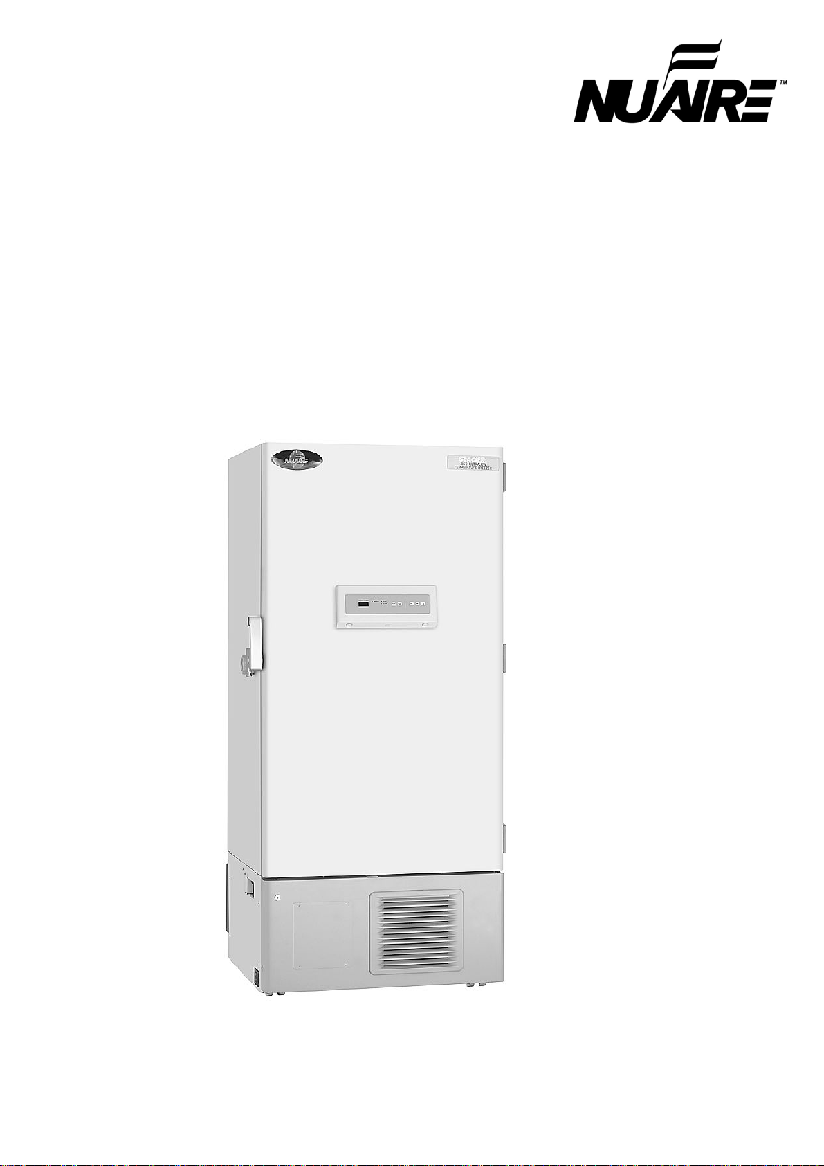
NuAire NU-9483E User manual

NU-9483E
NU-9483GC
NU-9483GA
NU-9668E
NU-9668GC
Ultra-Low Temperature Freezer
INSTRUCTION MANUAL
NU-9483GA

1
CONTENTS
INTRODUCTION P. 2
PRECAUTIONS FOR SAFE OPERATION P. 3
ENVIRONMENTAL CONDITIONS P. 7
FREEZER COMPONENTS P. 8
Control panel P.10
INSTALLATION SITE P.11
INSTALLATION P.12
START-UP OF UNIT P.13
CHAMBER TEMPERATURE SETTING P.14
KEY LOCK FUNCTION P.14
ALARM TEMPERATURE SETTING P.15
SETTING OF ALARM RESUME TIME P.16
REMOTE ALARM TERMINAL P.17
CHANGE OF COMPRESSOR DELAY TIME P.18
ALARMS & SAFETY FUNCTIONS P.19
ROUTINE MAINTENANCE P.20
Cleaning of cabinet P.20
Cleaning of condenser filter P.20
Defrosting of inside wall P.21
Cleaning of air intake port P.21
TROUBLESHOOTING P.22
DISPOSAL OF UNIT P.23
Recycle of battery P.23
Decontamination of unit P.23
DISPOSAL OF BATTERY P.28
TEMPERATURE RECORDER (OPTION) P.29
Setting of MTR-G85A and MTR-G85C P.29
Installation of MTR-G85A and MTR-G85C P.30
BACKUP COOLING KIT (OPTION) P.31
INVENTORY RACK P.32
SPECIFICATIONS (NU-9483E/9483GC/9483GA) P.33
SPECIFICATIONS (NU-9668E/9668GC) P.34
PERFORMANCE P.35
SAFETY CHECK SHEET P.36

2
INTRODUCTION
Read this manual carefully before using the appliance and follow the instructions for safety operation.
Never guarantee any safety if the appliance is used for any objects other than intended use or used by
any procedures other than those mentioned in this manual.
Keep this manual in an adequate place to refer to it as necessary.
The contents of the manual will be subjected to change without notice due to the improvement of
performance or functions.
Contact our sales representative or agent if any page of the manual is lost or page order is incorrect.
Contact our sales representative or agent if any point in this manual is unclear or if there are any
inaccuracies.
No part of this manual may be reproduced in any form without the expressed written permission of
NUAIRE.

3
PRECAUTIONS FOR SAFE OPERATION
It is imperative that the user complies with this manual as it contains
important safety advice.
Items and procedures are described so that you can use this unit correctly and safely.
If the precautions advised are followed, this will prevent possible injury to the user and
any other person.
Precautions are illustrated in the following way:
WARNING
Failure to observe WARNING signs could result in a hazard to personnel
possibly resulting in serious injury or death.
CAUTION
Failure to observe CAUTION signs could result in injury to personnel and
damage to the unit and associated property.
Symbol shows;
this symbol means caution.
this symbol means an action is prohibited.
this symbol means an instruction must be followed.
Be sure to keep this manual in a place accessible to users of this unit.
Some warning and/or caution labels are attached on the unit. Following shows the description of such
labels.
This label is on the cover in which the electrical components of high voltage are enclosed
to prevent the electric shock. The cover should be removed by a qualified engineer or a
service personnel only.
This symbol means attention or refer to document.
This symbol means earth.
This symbol means power switch “ON”.
This symbol means power switch “OFF”.
WARNING
As with any equipment that uses CO
2
gas, there is a likelihood of oxygen depletion in the
vicinity of the equipment. It is important that you assess the work site to ensure there is
suitable and sufficient ventilation. If restricted ventilation is suspected, then other methods of
ensuring a safe environment must be considered. These may include atmosphere monitoring
and warning devices.

4
PRECAUTIONS FOR SAFE OPERATION
Do not use the unit outdoors.
Current leakage or electric shock may result if the unit is exposed to
rain water.
Only qualified engineers or service personnel should install the unit.
The installation by
unqualified personnel may cause electric shock or fire.
Install the unit on a sturdy floor and take an adequate precaution to prevent the unit from
turning over.
If the floor is not strong enough or the installation site is not adequate, this may result
in injury from the unit falling or tipping over.
Never install the unit in a humid place or a place where it is likely to be splashed by water.
Deterioration of the insulation may result which could cause current leakage or electric shock.
Never install the unit in a flammable or volatile location.
This may cause explosion or fire.
Never install the unit where acid or corrosive gases are present
as current leakage or electric
shock may result due to corrosion.
Always ground (earth) the unit to prevent electric shock.
If the power supply outlet is not
grounded, it will be necessary to install a ground by qualified engineers.
Never ground the unit through a gas pipe, water main, telephone line or lightning rod.
Such
grounding may cause electric shock in the case of an incomplete circuit.
Connect the unit to a power source as indicated on the rating label attached to the unit.
Use of
any other voltage or frequency other than that on the rating label may cause fire or electric shock.
Never store volatile or flammable substances
in this unit if the container cannot be sealed. These
may cause explosion or fire.
Do not insert metal objects such as a pin or a wire into any vent, gap or any outlet
on the unit.
This may cause electric shock or injury by accidental contact with moving parts.
Use this unit in safe area when treating the poison, harmful or radiate articles.
Improper use
may cause bad effect on your health or environment.
Turn off the power switch (if provided) and disconnect the power supply to the unit prior to any
repair or maintenance
of the unit in order to prevent electric shock or injury.
Do not touch any electrical parts (such as power supply plug) or operate switches with a wet
hand.
This may cause electric shock.
WARNING

5
PRECAUTIONS FOR SAFE OPERATION
Ensure you do not inhale or consume medication or aerosols
from around the unit at the time of
maintenance. These may be harmful to your health.
Never splash water directly onto the unit
as this may cause electric shock or short circuit.
Never put containers with liquid on the unit
as this may cause electric shock or short circuit when
the liquid is spilled.
Never bind, process, or step on the power supply cord, or never damage or break the power
supply plug.
A broken supply cord or plug may cause fire or electric shock.
Do not use the supply cord if its plug is loose.
Such supply cord may cause fire or electric shock.
Never disassemble, repair, or modify the unit yourself.
Any such work carried out by an
unauthorized person may result in fire, or electric shock or injury due to a malfunction.
Disconnect the power supply plug if there is something wrong with the unit.
Continued
abnormal operation may cause electric shock or fire.
When removing the plug from the power supply outlet, grip the power supply plug,
not the cord.
Pulling the cord may result in electric shock or fire by short circuit.
Disconnect the power supply plug
before moving the unit. Take care not to damage the power
cord. A damaged cord may cause electric shock or fire.
Disconnect the power plug when the unit is not used for long periods.
Keeping the connection
may cause electric shock, current leakage, or fire due to the deterioration of insulation.
If the unit is to be stored unused in an unsupervised area for an extended period,
ensure that
children do not have access and that doors cannot be closed completely.
The disposal of the unit should be accomplished by appropriate personnel.
Remove doors to
prevent accidents such as suffocation.
Do not put the packing plastic bag within reach of children
as suffocation may result.
WARNING

6
PRECAUTIONS FOR SAFE OPERATION
Use a dedicated power source
(a dedicated circuit with a breaker) as indicated on the rating label
attached to the unit. A branched circuit may cause fire resulting from abnormal heating.
Connect the power supply plug to the power source firmly after removing the dust on the plug.
A dusty plug or improper insertion may cause a heat or ignition.
Never store corrosive substances such as acid or alkali
in this unit if the container cannot be
sealed. These may cause corrosion of inner components or electric parts.
Check the setting when starting up of operation after power failure or turning off of power
switch.
The stored items may be damaged due to the change of setting.
Be careful not to tip over the unit
during movement to prevent damage or injury.
Prepare a safety check sheet
when you request any repair or maintenance for the safety of service
personnel.
CAUTION

7
ENVIRONMENTAL CONDITIONS
This equipment is designed to be safe at least under the following conditions (based on the IEC 61010-1):
Indoor use;
Altitude up to 2000 m;
Ambient temperature 5
o
C to 40
o
C
Maximum relative humidity 80% for temperature up to 31
o
C decreasing linearly to 50% relative humidity
at 40
o
C;
Mains supply voltage fluctuations not to exceed
±
10% of the nominal voltage;
Transient overvoltages up to the levels of OVERVOLTAGE CATEGORY II;
Temporary OVERVOLTAGES occurring on the mains supply;
Applicable pollution degree of the intended environment (POLUTION DEGREE 2 in most cases)
EC Regulation No. 842/2006 on Certain Fluorinated Greenhouse Gases
Do not vent R-404A, R508B into the atmosphere:
These are fluorinated greenhouse gases, covered by the KYOTO PROTOCOL, With global warning
potential (GWP) = 3920, 11950.

8
16
17
18
19
FREEZER COMPONENTS
14
2
3
5 4
9
1
NU-9668E
6
7
8
11
10
15
12
14
13

9
FREEZER COMPONENTS
1.
Outer door:
To open the door, grip the handle. On closing, lock two door latches completely.
2. Control panel:
Temperature set key, buzzer key and alarm lamp etc. are installed on the panel.
Digital temperature display is also provided on it. See page 10 “Control panel”.
3. Condenser filter (behind the grille):
This filter prevents the dust from accumulating on the
condenser. The dusty filter may cause failure of refrigerating device. Clean the filter once a month.
See page 20 “Routine maintenance” for the cleaning.
4. Space for temperature recorder:
A temperature recorder (optional part) can be attached here. See
page 29 “Temperature recorder (OPTION)”.
5. Key hole:
Turn counterclockwise to 180 degree and the outside door can be securely locked.
6. Leveling foot:
2 feet are provided on the front side (right and left). Keep the unit in level by
adjusting these feet at the installation.
7. Caster:
4 casters are provided to facilitate moving of the cabinet.
8. Air intake port:
After closing the outer door, if used to open soon. See page 17
9. Door latch:
Always lock the latches when the outer door is closed.
10. Magnetic door gasket:
This provides a tight door seal and prevents cold air leak. Keep clean.
11. Inner door latch:
Always lock the inner door latch when the inner door is closed.
12. Inner door:
Composed of separated door flaps for minimizing temperature rise when putting in and
taking out refrigerated articles. Lock the door latch completely when the door is closed. The door is
removable for cleaning or defrosting. See page 21 “Routine maintenance”.
13.
Shelf:
Use to store the materials in the freezer. It is recommended to store the items on the shelf.
The maximum load is 50 kg.
Note:
Never touch the storage items with wet hands. Touching with the wet hands may cause frostbite.
Take care when handling shelves, as you may be injured if shelves drop on your leg.
14. Setting spot for temperature sensor:
The sensor of temperature controller is set at this spot. Be
careful not to contact any refrigerated articles directly with the spot.
15. Access port:
This is used for leading the measuring cable from the freezing chamber to the outside.
16.
Remote alarm terminal:
This is used to notice an alarm condition of the unit to remote location.
Refer to page 17 “Remote alarm terminal”.
17. Battery switch:
This is a switch for a battery for power failure alarm. Normally, turn on this switch.
Be sure to turn off this switch if the freezer is not in operating for the long period (over one month).
18. Power switch:
This is for turning ON/OFF the power to the unit. ON – “I” OFF – “
○
”
19. Fuse:
AC 250 V, 5 A is attached.

10
FREEZER COMPONENTS
Control panel
1. Digital temperature indicator:
This indicator shows the present chamber temperature or set
temperature.
2. Battery check lamp (BATTERY):
This lamp flickers to recommend the battery replacement. For the
replacement, consult our sales representative or agent.
3. Alarm lamp (ALARM):
This lamp is flashed during alarm condition.
4. Filter check lamp (FILTER):
This lamp lights when the excessive dust is accumulated on the
condenser filter. When this lamp lights, clean the condenser filter following the procedure on page 20.
5. Numerical value shift key ( ):
Pressing this key in the setting mode causes the numerical value to
shift. ON-OFF of key lock can be selected by pressing this key in the key lock mode. By pressing this
key for more than 5 seconds in the temperature display mode leads setting mode for alarm temperature
and alarm resume time. Refer to page 15 and 16 for details respectively.
6. Digit shift key ( ):
Pressing this key in the setting mode causes the changeable digit to shift. Key
lock is available by pressing this key for more than 5 seconds in the temperature display mode. Refer to
page 14 for details.
7. Set key (SET):
Temperature setting mode is led by pressing this key and the changeable digit is
flashed. By pressing this key again, the setting is memorized. The set mode returns to the temperature
display mode automatically when 90 seconds has passed without any key operation. Refer to page 14
for details.
8. Alarm test key (ALARM TEST):
To check the alarm system. Pressing this key with the battery
switch ON gets the alarm lamp to flash, the remote alarm to operate, and the buzzer to sound.
9. Alarm buzzer stop key (BUZZER):
To silence the audible alarm under alarm condition, press this
key. The buzzer during alarm test cannot be silenced by this key.
9 87 6
4
5
2
1 3

11
INSTALLATION SITE
To operate this unit properly and to obtain maximum performance, install the unit in a location with the
following conditions:
A location not subjected to direct sunlight
Do not install the unit under direct sunlight. Installation in a location subjected to direct sunlight cannot
obtain the intended performance.
A location with adequate ventilation
Leave at least 10 cm around the unit for ventilation. Poor ventilation will result in a reduction of the
performance and consequently the failure.
A location away from heat generating sources
Avoid installing the unit near heat-emitting appliances such as a heater or a boiler etc. Heat can
decrease the intended performance of the unit.
A location with little temperature change
Install the unit under stable ambient temperature. The allowable ambient temperature is between +5 and
+30
o
C.
A location with a sturdy and level floor
Always install the unit on a sturdy and level floor. The uneven floor or tilted installation may cause failure
or injury. Install the unit in stable condition to avoid the vibration or noise. Unstable condition may
cause vibration or noise.
WARNING
Install the unit on a sturdy floor.
If the floor is not strong enough or the installation site is not adequate,
this may result in injury from the unit falling or tipping over.
Select a level and sturdy floor for installation.
This precaution will prevent the unit from tipping.
Improper installation may result in water spillage or injury from the unit tipping over.
A location not prone to high humidity
Install the unit in the ambient of 80% R.H. or less humidity. Installation under high humidity may cause
current leakage or electric shock.
WARNING
Do not use the unit outdoors.
Current leakage or electric shock may result if the unit is exposed to rain
water.
Never install the unit in a humid place or a place where it is likely to be splashed by water.
Deterioration of the insulation may result which could cause current leakage or electric shock.
A location without flammable or corrosive gas
Never install the unit in a flammable or volatile location. This may cause explosion or fire or may result in
the current leakage or electric shock by the corrosion of the electrical components.
A location without the possibility of anything fall
Avoid installing the unit in the location where anything can fall down onto the unit. This may cause the
breakdown or failure of the unit.
Wire gage to the outlet from distribution box (NU-9483GA only)
The recommended wire gage to the outlet from distribution box (breaker box from electrical supply to
receptacle unit is plugged into) is dependant on *length of wire*, the following information is a good rule of
thumb to follow:
・
60ft or less 12ga
・
60ft - 100ft 10ga
・
100ft - 150 ft 8ga
・
150ft - 250ft 6ga

12
INSTALLATION
1.
Removing the packaging materials and tapes
Remove all transportation packaging materials and tapes. Open the doors and ventilate the unit. If the
outside panels are dirty, clean them with a diluted neutral dishwashing detergent. (Undiluted detergent
can damage the plastic components. For the dilution, refer to the instruction of the detergent.) After the
cleaning with the diluted detergent, always wipe it off with a wet cloth. Then wipe off the panels with a dry
cloth.
Note:
Remove the cable tie banding the power supply cord.
Prolonged banding may cause the corrosion of the
cord coating.
2.
Adjusting the leveling foot
Extend the leveling feet by rotating them
counterclockwise to contact them to the floor.
Ensure the unit is level. (Fig.1)
3.
Fixing the unit
Two fixtures are attached to the rear of the frame.
Fix the frame to the wall with these fixtures and rope
or chain. (Fig. 2)
4. Power source (NU-9483GA only)
For stable and reliable cooling operation, check the
following items before connecting the freezer to a
power source. (Fig. 3)
Voltage of the power source: 115 V, 60 Hz
Receptacle of the power source: NEMA reference
5-20R
(The equipment has a NEMA 5-20P plug.)
If not, it is necessary to install 5-20R receptacle by
qualified engineers.
Current capacity of the power source: 20 amperes
Rating amperage of the circuit breaker or fuse used in
the power line: 20 amperes
(Use item delay type in case of fuse.)
Do not connect the other equipment.
5.
Ground (earth)
The ground (earth) is for preventing the electric shock in the case of the electrical insulation is somehow
degraded. Always ground the unit at the time of installation.
WARNING
Use a power supply outlet with ground (earth)
to prevent electric shock. If the power supply outlet is
not grounded, it is necessary to install a ground by qualified engineers.
Never ground the unit through a gas pipe, water main, telephone line or lightning rod.
Such
grounding may cause electric shock in the case of an incomplete circuit.
6. Installing the earth leakage breakers
This product is to connect a earth leakage breaker to the power supply side of the product.
Contact our sales representative or agent at the time of installation of the
earth leakage
breaker.
Leveling foot Fig.1
Fixture Fig. 2
Fig. 3
5-20P 5-20R

13
START-UP OF UNIT
Follow the procedures for the initial and consequent operations of the unit.
1.
Turn off the switch of the backup cooling kit (optional component) if it is installed.
2.
Connect the power cord to the dedicated outlet having appropriate rating with the chamber empty, and
turn on the power switch on the freezer.
3.
Turn on the battery switch.
4.
Set the desired chamber temperature. See page 14 for the temperature setting.
5.
Check that the chamber temperature reaches the desired temperature.
6.
Turn on the switch of backup cooling kit (optional component) if it is installed.
7.
Make sure that the alarm lamp blinks and the buzzer sounds by pressing the alarm test key (ALARM
TEST). The remote alarm is also operated. E09 is displayed on the digital temperature indicator if the
battery switch is OFF. Make sure to turn on the battery switch.
8.
After confirming the above, you can put articles into the freezer chamber in a small batch to prevent the
temperature rise.
CAUTION
Do not put too many warm articles in the chamber. The temperature rise may cause the damage
to the articles in the chamber.
WARNING
Fix the shelf supports and shelves securely. Incomplete installation may cause injury or damage.
Operation after power failure
The set value is memorized by nonvolatile memory. Accordingly, the freezer resumes the operation with
setting before power failure.
When the freezer is recovered from power failure with the chamber temperature higher than the preset
temperature, then the high temperature alarm is activated and the buzzer sounds and the remote alarm is
also activated. Push the buzzer stop key (BUZZER) to silence buzzer and take appropriate actions if
needed.
WARNING
When this product operates at the first start-up or after no use for long period, the built-in battery capacity
may be lowered or completely zero because of discharge of the battery. After installation the product, the
freezer should operate for more than 3 days (72 hours) to charge the battery.
Note:
When the power is turned on, it may take 30 up to 60 minutes (depending on the ambient temperature) to
start the compressor in order to reduce stress after being idle for extended periods of time.
This is an intended operation therefore please keep the power on until the freezer actually starts
running.
(NU-9483GA only)

14
CHAMBER TEMPERATURE SETTING
Table 1 shows the basic procedure for setting the chamber temperature. Perform key operations in the
sequence indicated in the table. The example in the table is based on the assumption that the desired
temperature is -75
o
C.
Note:
The unit is set at the factory that the chamber temperature -80
o
C.
Table 1. Basic operation sequence (Example: Chamber temperature -75
o
C, Ambient temperature 20
o
C
)
Description of operation Key operated Indication after operation
1
Turn the power switch ON.
---- The current chamber temperature is
displayed.
2 Press set key. SET The second digit is flashed.
3 Set to -75 with the numerical value
shift key and digit shift key.
When pressed, the figure of settable
digit changes.
When pressed, the settable digit
is shifted.
4 Press set key. SET Set temperature is memorized and the
current chamber temperature is
displayed.
Note:
• The temperature set mode returns to the temperature display mode automatically when 90 seconds has
passed without any key operation.
• Although the value of the chamber temperature setting can range from -50
o
C to -90
o
C, the guaranteed
temperature when there is no load is -86
o
C when the ambient temperature is 30
o
C.
KEY LOCK FUNCTION
This unit is provided with the key lock function. When the key lock is ON, change of temperature setting
through the key pad is not available. The key lock is set in OFF at the factory.
Display Mode Function
L 0 Key lock is OFF Enable to change of temperature setting
L 1 Key lock is ON Disable to change of temperature setting
Table 2. Procedure for key lock setting (change from key lock OFF to key lock ON)
Description of operation Key operated Indication after operation
1 ---- The current chamber temperature is
displayed.
2 Press digit shift key for 5 seconds.
The first digit is flashed.
3 Press numerical value shift key
and scroll the figure to 1. When pressed, the figure of settable
digit changes.
4 Press set key. SET The key lock is set to ON.
The current chamber temperature is
displayed.
• The key lock set mode returns to the temperature display mode automatically when 90 seconds has
passed without any key operation.

15
ALARM TEMPERATURE SETTING
This unit is provided with the high and low temperature alarm and the temperature at which the alarm is
activated is changeable.
The following procedure shows the setting of alarm temperature according to the condition below:
High temperature alarm: activates at the temperature 5
o
C higher than the set temperature
Low temperature alarm: activates at the temperature 5
o
C lower than the set temperature
Note:
The alarm temperature is set at the factory 10
o
C higher and lower than the set temperature.
The available range of alarm temperature is between 5
o
C and 40
o
C higher or lower than the set
temperature.
Table 3. Procedure for setting high temperature alarm
Description of operation Key operated Indication after operation
1 ---- The current chamber temperature is
displayed.
2 Press numerical value shift key for
about 5 seconds.
The first digit is flashed.
3 Press numerical value shift key
and scroll the figure to 1. When pressed, the figure of settable
digit changes.
4 Press set key. SET The current setting is displayed and
the first digit is flashed.
5 Scroll the figure to 005 by using
digit shift key and numerical value
shift key.
When pressed, the figure of settable
digit changes.
When pressed, the changeable digit
is shifted.
6 Press set key. SET Alarm temperature is memorized and
the current chamber temperature is
displayed.
Table 4. Procedure for setting low temperature alarm
Description of operation Key operated Indication after operation
1 ---- The current chamber temperature is
displayed.
2 Press numerical value shift key for
about 5 seconds.
The first digit is flashed.
3 Press numerical value shift key
and scroll the figure to 2. When pressed, the figure of settable
digit changes.
4 Press set key. SET The current setting is displayed and
the first digit is flashed.
5 Scroll the figure to -05 by using
digit shift key and numerical value
shift key.
When pressed, the figure of settable
digit changes.
When pressed, the changeable digit
is shifted.
6 Press set key. SET Alarm temperature is memorized and
the current chamber temperature is
displayed.
• The alarm temperature set mode returns to the temperature display mode automatically when 90
seconds has passed without any key operation.

16
SETTING OF ALARM RESUME TIME
The alarm buzzer is silenced by pressing alarm buzzer stop key (BUZZER) on the control panel during
alarm condition (The remote alarm is not silenced).
The buzzer will be activated again after certain suspension if the alarm condition is continued. The
suspension time can be set by following the procedure shown in the Table 5 below.
The example in the table is based on the assumption that the desired duration is 20 minutes.
Note:
The duration is set in 30 minutes at the factory.
Table 5. Setting procedure for alarm resuming time (change from 30 minutes to 20 minutes)
Description of operation Key operated Indication after operation
1 ---- The current chamber temperature is
displayed.
2 Press digit shift key for 5 seconds.
The first digit is flashed.
3 Set the figure to F25 with the digit
shift key and numerical value shift
key.
The settable digit is shifted.
When pressed, the figure of settable
digit changes.
4 Press set key. SET The current resume time is displayed.
The second digit is flashed.
5 Scroll the figure to 020 with the
numerical value shift key. When pressed, the figure of settable
digit changes.
6 Press set key. SET The setting is memorized and
the current chamber temperature is
displayed.
• The settable alarm resume time is 10, 20, 30, 40, 50, or 60 minutes (The setting is 010, 020, 030, 040,
050, or 060). The buzzer would not resume if the resume time is set in 000.
• It is recommended to set the alarm resume time when the freezer is not under alarm condition. The
setting during alarm condition is effective on the next alarm condition.
• The setting cannot be changed during power failure.
• The remote alarm during power failure or buzzer and remote alarm during alarm test cannot be silenced.
• The alarm resume time set mode returns to the temperature display mode automatically when 90
seconds has passed without any key operation.

17
REMOTE ALARM TERMINAL
The terminal of the remote alarm is installed at the lower left side of the unit. The alarm is outputted from
this terminal.
Contact output:
between COM. and N.O. between COM. and N.C.
At normal Open Close
At abnormal Close Open
Note:
• The alarm buzzer is silenced by pressing alarm buzzer stop key (BUZZER) on the control panel during
alarm condition. (A remote alarm is continuing the operation.)
The buzzer will be activated again after certain suspension if the alarm condition is continued.
• The alarm is actuated when the power supply plug is disconnected from the outlet or the power switch is
OFF.
AIR INTAKE PORT
When the outer door is closed and opened soon, a outer door
sometimes does not open.
The warm air which went into the chamber is cooled down rapidly, and
this is because air inside the chamber contracted.
Follow the procedure below when the outer door is closed and opened
soon:
1.
Turn the cap of the left side counterclockwise, about two laps. (or
remove the cap.)
2.
Allow about twenty seconds before open the outer door.
3.
Close (or replace) the cap when the door operation is completed.
The outer door may not open in the above method when there are frost and ice in the air intake port. In
that case, open the cap and check the frost inside the air intake port. Remove the frost inside the air
intake port. Clean the air intake port every month even when there is no frost in the air intake port.
Refer to page 21 for the cleaning.
WARNING
For removing the frost of the air intake port, do not use a tool with sharp edge such as a knife or a screw
driver.
Replace the cap when the air intake port is not used. Improper replacement may cause rise of chamber
temperature or condensation around the air intake port.
Cap

18
CHANGE OF COMPRESSOR DELAY TIME
The delay time of high and low stage side compressor can be changed to reduce the load on the power
line and to facilitate the start-up (reset) of the freezer after power failure.
The example in the table is based on the assumption that the delay time is changed to 4 minutes.
(The delay time is set in 2 minutes at the factory.)
Note:
• The delay time should be the same for high stage side and low stage side compressors.
• The setting range for delay time is between 2 and 15 minutes. The cool down of chamber temperature
may be slow when the setting of delay time is over 5 minutes, depending on the installation environment.
There is no need of changing the delay time when the capacity of power source is adequate.
Table 6. Changing procedure for delay time (change from 2 minutes to 4 minutes)
Description of operation Key operated Indication after operation
1 ---- The current chamber temperature is
displayed.
2 Press numerical value shift key for
5 seconds.
The first digit is flashed.
3 Set the figure to F05 with the
numerical value shift key. When pressed, the figure of settable
digit changes.
4 Press set key. SET The current delay time is displayed.
The first digit is flashed.
5 Set the figure to 004 with the
numerical value shift key. When pressed, the figure of the first
digit changes.
6 Press set key. SET The delay time is memorized and
the current chamber temperature is
displayed.
• The compressor starts to operate with the delay time set by the above procedure at the time of power on
or after power failure. However, the start up of the low stage side compressor is affected by the chamber
temperature and the cascade condenser temperature. The delay time varies depending on how they
meet the start up conditions.
• The compressor delay time set mode returns to the temperature display mode automatically when 90
seconds has passed without any key operation.

19
ALARMS & SAFETY FUNCTIONS
This unit has the alarms and safety functions shown in Table 7, and also self diagnostic functions.
Table 7. Alarms and safety functions
Alarm & Safety Situation Indication Buzzer Safety operation
High temperature
alarm
If the chamber temperature is higher
than the temperature at which the
high temperature alarm is activated. Alarm lamp is flashed.
Temperature indicator is
flashed.
Intermittent tone with
15 minutes delay. Remote alarm with 15
minutes delay.
Low temperature
alarm
If the chamber temperature is lower
than the temperature at which the
low temperature alarm is activated.
Power failure alarm When the power to the unit is
disconnected. Alarm lamp is flashed. Intermittent tone Remote alarm.
Filter check When the condenser filter is clogged. Filter check lamp lights. Intermittent tone -----
Battery check When about 3 years has passed with
power switch ON. Battery check lamp blinks. ----- -----
Auto-return When there is no key pressing in
each setting mode for 90 seconds. Chamber temperature is
displayed. ----- Finishing of each
setting mode.
Key lock When the key lock is ON. ----- ----- Change of setting is
disable.
Sensor abnormality
If the thermal sensor is disconnected. Alarm lamp is flashed.
E01 and chamber temp.
are displayed alternately.
Intermittent tone Remote alarm.
Unit keeps continuous
running.
If the thermal sensor is short-circuited. Alarm lamp is flashed.
E02 and chamber temp.
are displayed alternately. Intermittent tone Remote alarm.
Unit keeps continuous
running.
If the cascade sensor is disconnected. Alarm lamp is flashed.
E03 and chamber temp.
are displayed alternately.
Intermittent tone Remote alarm.
If the cascade sensor is short
circuited.
Alarm lamp is flashed.
E04 and chamber temp.
are displayed alternately.
Intermittent tone Remote alarm.
If the filter sensor is disconnected. Alarm lamp is flashed.
E05 and chamber temp.
are displayed alternately. Intermittent tone Remote alarm.
If the filter sensor is short-circuited. Alarm lamp is flashed.
E06 and chamber temp.
are displayed alternately. Intermittent tone Remote alarm.
If the ambient temperature sensor is
disconnected.
Alarm lamp is flashed.
E07 and chamber temp.
are displayed alternately. Intermittent tone Remote alarm.
If the ambient temperature sensor is
short-circuited.
Alarm lamp is flashed.
E08 and chamber temp.
are displayed alternately. Intermittent tone Remote alarm.
Battery switch
check When the battery switch is OFF during
alarm test. Alarm lamp is flashed.
E09 is flashed.
----- -----
Condenser temp.
abnormality In the event of failure of fan motor for
cooling the compressor E10 and chamber temp.
are displayed alternately. Intermittent tone Remote alarm.
Compressor of high
stage side stops.
Note:
• When the operation is started in high ambient temperature, the filter check lamp is sometimes flashed.
In this case, the lamp is off automatically when the chamber temperature is getting lower.
• The freezer resumes the operation after power failure with the temperature setting before power failure
as the chamber temperature setting and alarm temperature setting are memorized in the volatile memory.
• The battery for power failure alarm is an article for consumption. It is recommended that the battery will
be replaced about every 3 years. Contact NUAIRE sales representative or agent at the time of
replacement of the battery for recycling.
• Fan motors are expendable supplies. Exchange it for about every 6 years. Contact NUAIRE sales
representative or agent at the time of replacement of the fan motor.
• A compressor may repeat on-off by the program when product start after suspend operation long time.
A program functions and a compressor may repeat on-off even if it is turn on the power when it is stop a
product for a long time.(Ex: In such cases as the battery exchange)
This manual suits for next models
4
Table of contents
Other NuAire Freezer manuals
Popular Freezer manuals by other brands

Samsung
Samsung RZ32T Series user manual

Zanussi
Zanussi ZFU20200WA user manual

Baumatic
Baumatic BRCI7031 instruction manual

Tricity Bendix
Tricity Bendix U28025 TBUL 140 Operating and installation instructions

Zanussi
Zanussi ZF 56/45 Instructions for the use and care

Frigidaire
Frigidaire FFR32GFELT user manual