NueTec AT4K Specification sheet
Operation and Installation Manual
AT4K
HDMI 2.0 Generator/Analyser
NueTec is a division of Nue World Ltd.
Copyright Nue World Ltd. 2017

The AT4K HDMI 2.0a Generator / analyser has been tested certified and conforms to all
safety regulations and requirements.
Please take time to carefully read the safety instruction and advise given below.
●Follow all instructions and warnings marked on this unit.
●Do not attempt to service this unit yourself, except where explained in this manual.
●Provide proper ventilation and air circulation and do not use near water.
●Ensure that objects, chemical or materials that might damage the device kept away from
it.
●Please ensure that this devise will be kept well away from dump or wet surfaces and envi-
ronments.
●Use only the power supply power cords and connection cables designed and supplied
for this unit.
●Do not use liquid or aerosol cleaners to clean this unit. Always unplug the power to the
device before cleaning.
SAFETY INSTRUCTIONS
Please read carefully
Table Of Content
1. General Description/Main Features/In The Box/Prior To Use
2. Specifications
3. HDMI LLC Bandwidth and Colour Depth Chart
4. Front Panel/Panel’s Connections Applications
5. Operations/Functions
6. Selecting Signal Format
7. Selecting Signal Format (Cont.)
8. Rendering Test Pattern On A Display
9. Users Defined Patterns And Moving Blocks
10. Receiver And Analyser Function
11. HDCP Tester
12. HDCP Tester (Cont.)
13. EDID Analyser
14. Loop Test
15. Firmware/Software Upgrade
16. Firmware/Software Upgrade
17. Firmware/Software Upgrade
18. Unit’s Eye Patterns Tests

The AT4K HDMI 2.0 Generator / Analyzer is one of the most cost effective HDMI 2.0 tools ever launched. It
is a versatile HDMI 2.0 toolbox with full bandwidth and HDCP 2.2 analytical capabilities.
The AT4K is equipped with both HDMI 2.0 pattern generator as well as a signal analyser. The model is a
portable battery operated tool.
General Description
Main Features
• 1x AT4K
• 1x DC 12V 5A charger
In The Box
P1
• 4K 3840x2160 4:4:4 8bit, 4:2:0-4:4:4 10-16bit HDR pattern generator
4.3” touch panel
Supports mouse control
Firmware update through USB Flash Drive
Supports user defined pattern up to 2GB
Embedded LINUX KERNAL system with limitless extension
Scrambler support for videos output over 340MHz
Loop test capability providing statistics analysis for connection stability
Supports HDMI loop-through function
HDCP test allows verification of HDCP of a given HDMI source and transmission of HDCP
encrypted video
Qualify physical layer performance to ensure the best compatibility
Battery powered, portable. Extend operation, full charge providing up to 4 hours
Rechargeable battery design with short charging time of about 2 hours
Prior to using the AT4K it is necessary to ensure that the unit is disengaged from its
“Shipping Mode”. Please folow the steps below:
1. Connect the power supply/charger to an active wall outlet
2. Connect the power supply to the AT4K
3. Power the AT4K

Specifications
Technical
Model Name AT4K
Main use Generator / Analyzer
Video bandwidth Single link 600MHz [18Gbps]
HDMI compliance HDMI 2.0 and all previous versions
HDCP compliance HDCP 2.2 and all previous version
Video Support Up to 3840x2160 24-60Hz 4:4:4 8bit, 4:2:0 10-16bit (HDR)
Video Format Support HDMI
Audio support 8ch LPCM up to 192K
Control USB mouse / touch panel / Ethernet
ESD protection Human body model — ±15kV [air-gap discharge] & ±8kV [contact discharge]
Input 1x HDMI + 1xUSB + 1x RJ-45(Ethernet)
Output 1x HDMI + 1x 3.5mm(Stereo)
USB Support USB 2.0
HDMI connector Type A [19-pin female]
USB Connector Type A
RJ-45 connector WE/SS 8P8C with 2 LED indicators
Mechanical
Chassis Metal enclosure
Dimensions (L x W x H)
Model 1 05 x 166 x 42mm[4.1" x 6.6" x 1.7"]
Package 371 x 170 x 77mm[1'5" x 6.7" x 3"]
Carton 410 x 368 x 393mm[1'3" x 1'4" x 1'5"]
Weight
Net 765g [27oz]
Gross (inc. Box) 1294g [2.8 lbs]
Power supply/ Charger 12V 5A DC / Battrery
Power Consumption 15 Watts
Operation temperature 0~40°C [32~104°F]
Storage temperature -20~60°C [-4~140°F]
Relative humidity 20~90% RH [no condensation]
P2

HDMI LLC Bandwidth and Colour Depth Charts
Hz/Fps 8bit Bandwidth re-
quired (Gbps)
WGC
supported
10Bits
Bandwidth
required WGC supported
24 4:4:4 8.9 REC 709 4:4:4 Not supported REC 2020
25 4:4:4 8.9 REC 709 4:4:4 Not supported REC 2020
30 4:4:4 8.9 REC 709 4:4:4 11.1 REC 2020
50 4:2:0 8.9 REC 709 4:2:0 11.1 REC 2020
60 4:4:4 17.8 REC 709 4:4:4 Not supported REC 2020
P3
Please note:
The AT4K is built to measure and analyse HDMI connections, sources and sinks.
The unit stores a set of pre determined parameters that adhere to HDMI LLC standards and features.
●Resolutions
●Colour depth
●Colour sub-sampling
●Refresh rate /fps
All adhere to HDMI own standards. Please review the chart below.
Chart courtesy of HDMI LLC
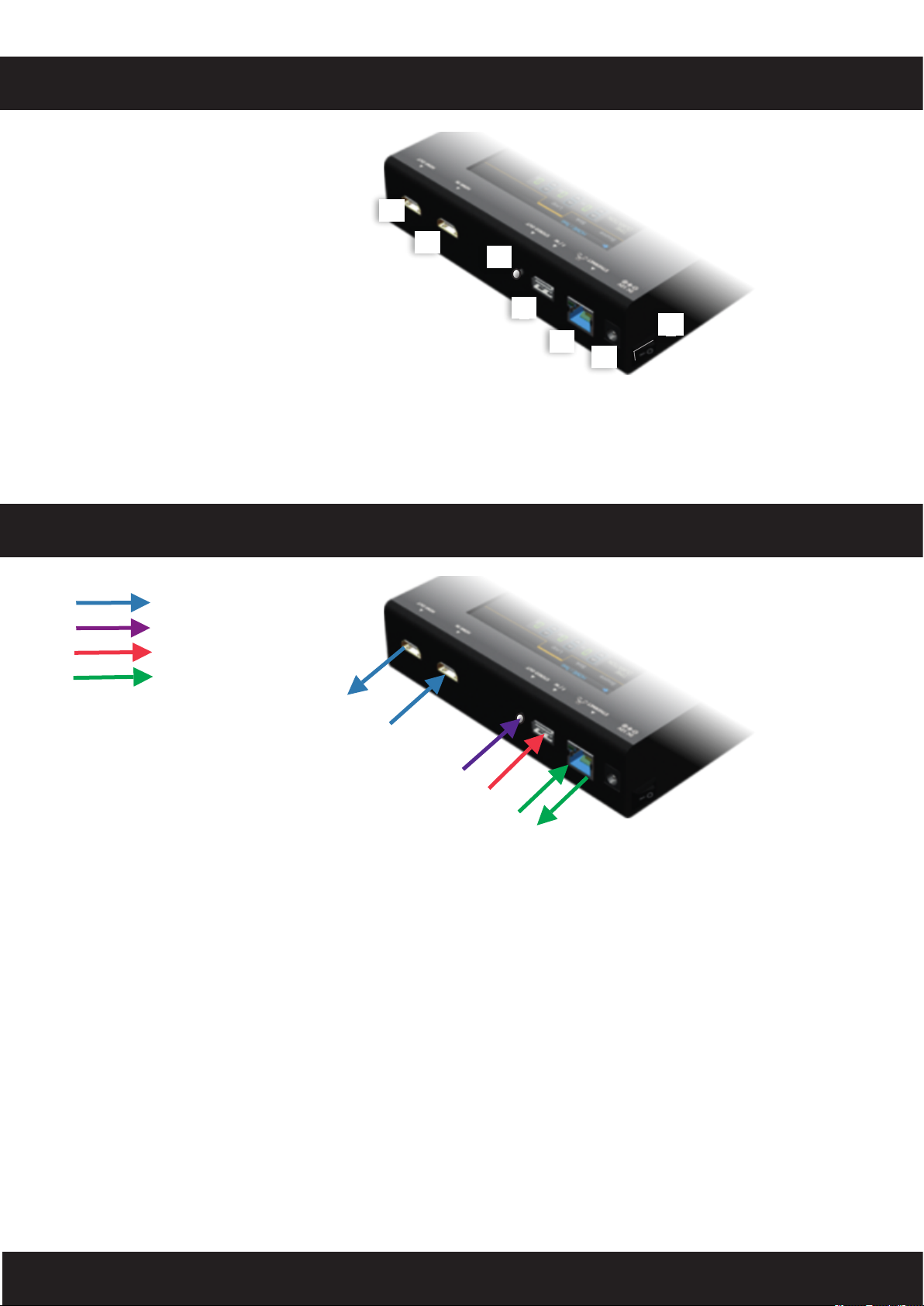
Front Panel
1. OUTPUT: HDMI output
2. INPUT: HDMI input
3. Stereo Out: 3.5mm Analogue audio output
4. USB: Connect to USB device for control or firmware update
5. Ethernet: Ethernet control
6. +12V DC: 12V 5A DC power jack
7. Power Switch: Power ON/OFF switch
8. Touch Panel: Touch screen for control
2
3
1
4
5
P4
Panel’s Connections applications
6
7
HDMI signal
Analogue audio
USB/mouse connection
Ethernet/router/cloud

P5
Operation / Functions
The major functions of the device are listed below
▪HDMI Generator
▪HDMI Receiver
▪HDCP Test
▪EDID Test
▪Loop Test
Please refer the table below and the following section for correct operations functions and instructions.
OUTPUT SETTINGS
Menu Items Instruction
TYPE select the HDMI/DVI signal type infor-
mation (color space and colour depth)
Signal Format
RESOLUTION setting the display resolution and fre-
quency
DEFAULT
multiple patterns to test HDMI devices,
it also provides installers timer and
moving squares
VIDEO Pattern
ALBUM
MUTE mute / un-mute the PCM audio
PCM Audio Tone
TONE Used for installer's setting the audio
information to test audio from AV
receiver/processors
Setting SCRAMBLER For installer's real-time information of
signal encode message status
TEST SETTING
Menu Items Instructions
FORMAT Read format information from source
Source
VIDEO Provides AT4K’s screen and installer
broadcast information and broadcast
pass through to a display
AUDIO
Reads audio information
PACKET Reads packet
HDCP Enables HDCP function (1.4-2.2)
Sink EDID Analyse EDID or acquire EDID from RX
or display
HDCP HDCP test
Loop Evaluates the quality of cables link and
connections
SYSTEM SETTING
Menu Items Action
SCREEN BRIGHTNESS
Adjust the screen brightness
Preference BEEP Switch system sound ON/OFF
Ethernet DHCP
STATIC IP
Firmware FIRMWARE UPGRADE
Battery BATTERY STATUS
ALL MENU’S ITEMS ARE SUBJECT TO CHANGE WITHOUT NOTIFICATION
P6
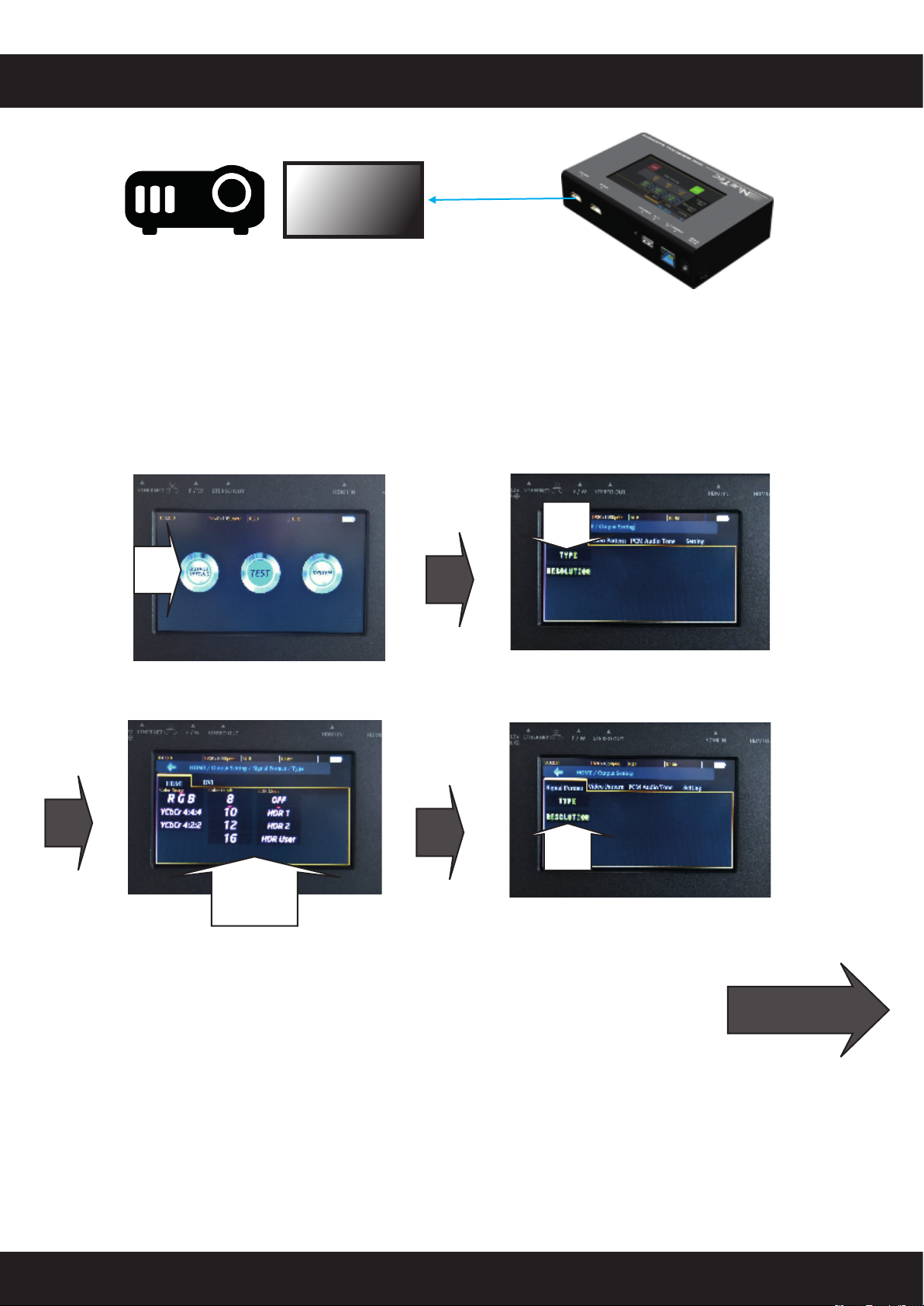
SELECTING SIGNAL FORMAT
1. Selecting the Signal Format
The AT4K provides different signal resolutions and types for installers to select from. Installers can
choose the Signal Format Tab to select the signal type desired (HDMI / DVI) and signal resolu-
tion (Flat screens/projector).
AV flat screens/projector resolution choices include resolution of up to 4096x2160 60Hz.
PC screens resolution choices include resolution of up to 1920x1200 60Hz.
Tap
Tap
Choose
Tap
Next page
Tap

P7
SELECTING SIGNAL FORMAT
1. Selecting the Signal Format
The AT4K provides different signal resolutions and types for installers to select from. Installers can
choose the Signal Format Tab to select the signal type desired (HDMI / DVI) and signal resolu-
tion (Flat screens/projector).
Flat screens/projectors resolution choices include resolution of up to 4096x2160 60Hz.
PC screens resolution choices include resolution of up to 1920x1200 60Hz.
Choose
Tap
Tap
Tap
Choose
Tap
P8
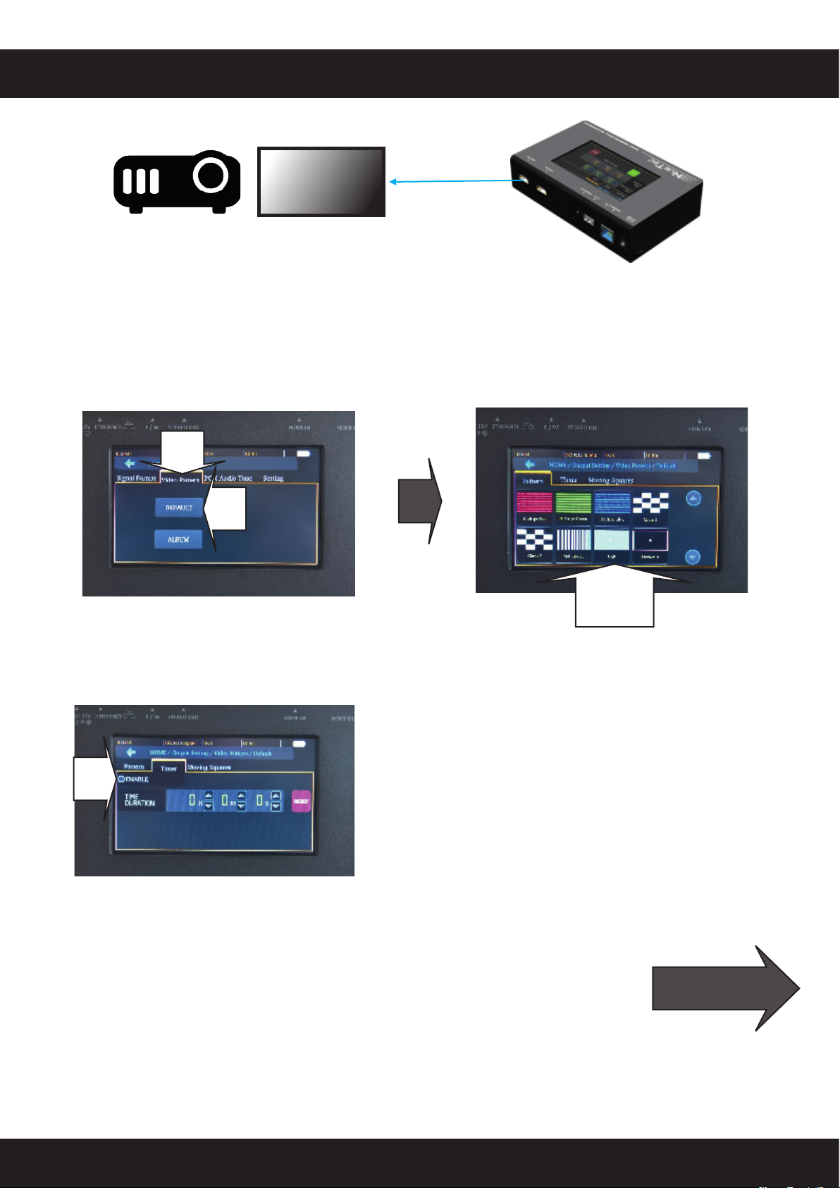
RENDERING TEST PATTERNS ON A DISPLAY
2. Rendering Test Patterns On A Display
The AT4K provides multiple test patterns for to select for testing AV flat screens/projectors. Install-
ers can select the desired test pattern from the Video Pattern menu.
3. User Defined Pattern
The AT4K also provides users defined patterns function for installer wishing to embed and use
custom test image. For more details please see the Upgrade section.
Next page
Tap
Tap
Timer Function (for optional use)
When enabled timer will be displayed on pattern
and will be displayed on screen.
To enable time please tap on ENABLE
Tap
Choose
Tap
Table of contents


