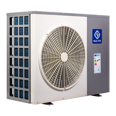
Nulite NE-C3BZ-B2F Owner's manual

DC INVERTER HEAT PUMP
Installation And Operation Instruction

1
CONTENT
I. Prologue...................................................................................................... 2
II. Feature ....................................................................................................... 3
1.Parameter .............................................................................................. 3
2.Dimensions............................................................................................ 4
3.The unit technical parameters................................................................ 7
III. Installation................................................................................................. 8
1. Operating Instruction............................................................................ 8
2.Heat pump installation......................................................................... 10
3.Circuit connection ............................................................................... 12
4. Trial running....................................................................................... 13
IV. Control system instruction....................................................................... 14
V. Daily Maintenance & Repair ..................................................................... 15
1. Maintenance....................................................................................... 15
2. Common problem............................................................................... 15
3. Error information code ....................................................................... 16
VI. Wiring drawing........................................................................................ 18

2
Please read this manual carefully before installation
◆The heat pump must be installed by the professional technician.
◆Please install the heat pump and connect the water pipe in accordance with this manual strictly.
◆For safety, please make sure to recheck everything before power on.
◆If the machine has any improvement, the content is subject to change without notice.
I. Prologue
Thanks for using heat pump water heater! Please read this manual carefully before installation and
operation! This manual contains the information about installation, commissioning, operation, and
maintenance. The following items should be focused:
1. Before installation, please confirm if your local voltage is match with the voltage showed on the
machine's nameplate and if the carrying capacity of the power supply, wires and sockets are suitable
for this machine's input power.
2. Users are not allowed to change the power cord or socket. Wiring work must be carried out by a
qualified electrician and ensure that the metal part of the machine has a good grounding. Changing the
ground mode is strictly forbidden.
3. After the completion of the construction of all wiring work, please make sure to recheck everything
is well before power on.
4. Installing the machine in the place which the combustible gas may leak is strictly forbidden.
5. Do not put your hands or foreign objects into the air outlet of heat pump unit, otherwise, it will be
dangerous to the people and equipment.
6. In order to obtain a better energy-saving effect, the unit should be installed in a place with
well-ventilated.
Read the Manual before Operation

3
ATTENTIONS:
1. Please make sure the water systems should be filled with water before the machine start working.
2. When the machine is operating, all the valves of the water systems must be in the open position.
3. If without inlet water or stop using for a long time, when re-boot the machine, please according to
the item of attentons 1.
4. A removable filter must be installed at the water inlet and please clean the valve periodically depend
on your locate water quality (every 2 or 3 months).
5. The maximum water temperature is 55C .When you use the water, please adjust the water
temperature to a appropriate temperature (The most comfortable water temperature for shower is
38~42 , if the water temperature above 50C , there will be danger of burns!)
6. The maintenance of the machine must be carried out by the professional personnel.
7. If the unit power off,please discharge all the water inside.Otherwise,the heat exchanger will be
frozen in winter.
II. Feature
1.Parameter
Model
Size(L*W*H mm)
Net Weight(KG)
Power Source
NE-C3BZ-B2F
1119*340*912
100
220V~50Hz
NE-C5BZ-B2F
1119*347*1249
135
220V~50Hz
NE-C6BZ-B2F
1119*347*1249
138
220V~50Hz
NE-C8BZ-B2IIF
1211*568*1496
155
380V~50Hz
NE-C10BZ-B2IIF
1211*568*1496
165
380V~50Hz

4
2.Dimensions
NE-C3BZ-B2F

5
NE-C5BZ-B2F/ NE-C6BZ-B2F

6
NE-C8BZ-B2IIF/ NE-C10BZ-B2IIF

7
3.The unit technical parameters
The Unit working parameters
Product Series
DC Inverter Heating and cooling machine series
Model
NE-C3BZ-B2F
NE-C5BZ-B2F
NE-C6BZ-B2F
Power Specifications(V~Hz)
220V~50Hz
220V~50Hz
220V~50Hz
Rated cooling capacity (W)
7500W
12500W
15000W
Rated refrigerating input power /
current (A)
2560W / 11.6A
4300W / 19.5A
5260W / 23.8A
Rated hot water heating capacity
(W)
8450W
14000W
16800W
Rated heating input power /
current (A)
2500W / 11.4A
4180W / 19.0A
5060W / 23.2A
Rated floor heating capacity(W)
5390W
9300W
10770W
Rated heating input power /
current (A)
2300W / 10.5A
4130W / 18.4A
4780W / 21.7A
Maximum input power / current
(A)
3250W / 14.8A
5400W / 24.5A
6500W / 29.5A
Refrigerant / weight
R410A/2200g
R410A/3000g
R410A/3300g
Specification for control panel
fuse wire
T6.3AL/250V
T6.3AL/250V
T6.3AL/250V
Ring temperature working range
(℃)
-25~43
-25~43
-25~43
Water temperature working
range(℃)
7~60
7~60
7~60
Water pressure working range
(MPa)
≤0.45
≤0.45
≤0.45
Rated water flow (m³/h)
1.29
2.15
2.58
outline dimension (mm)
1119*340*912
1119*347*1249
1119*347*1249
Water pipe diameter
G3/4"(inner)
G1"(inner)
G1"(inner)
Product Series
DC Inverter Heating and cooling machine series
Model
NE-C8BZ-B2IIF
NE-C8BZ-B2IIF
NE-C10BZ-B2IIF
Power Specifications(V~Hz)
220V~50Hz
380V 3N~50Hz
380V 3N~50Hz
Rated cooling capacity (W)
20000W
20000W
25000W
Rated refrigerating input power /
current (A)
7140W / 32.5A
7140W / 12.7A
8920W / 15.9A
Rated heating capacity(W)
22500W
22500W
28100W

8
Rated heating input power /
current (A)
7030W / 31.5A
7030W /12.5A
8460W / 15.1A
Ratedhot water heating
capacity(W)
14500W
14500W
18600W
Rated floor heating input power /
current (A)
6500W / 29.5A
6500W / 11.5A
8340W / 14.9A
Maximum input power / current
(A)
9280W / 42.2A
9280W / 16.6A
12030W / 21.5A
Refrigerant / weight
R410A/4800g
R410A/4800g
R410A/5000g
Specification for control panel
fuse wire
T6.3AL/250V
T6.3AL/250V
T6.3AL/250V
Ring temperature working range
(℃)
-25~43
-25~43
-25~43
Water temperature working
range(℃)
7~60
7~60
7~60
Water pressure working range
(MPa)
≤0.45
≤0.45
≤0.45
Rated water flow (m³/h)
3.44
3.44
4.3
outline dimension (mm)
1211*568*1496
1211*568*1496
1211*568*1496
Water pipe diameter
G1-1/2"(inner)
G1-1/2"(inner)
G1-1/2"(inner)
III. Installation
1. Operating Instruction
1. Safety Warning
(Not following the operation below, it may cause user injury or damage to the unit)
The heat pump
must be installed
by a professional
Installation or
maintenance of
the unit, must
ensure that the
grounding wire is
grounded safely
and reliably, and
is strictly
prohibited.
When powered off
or cannot be used,
the water of the
heat pump unit
must be released,
otherwise the
warranty will not
be guaranteed after
the damage.
Do not use mobile
outlets, damaged
power cords and
outlets
The inner tank is
forbidden to be
energized before
filling full of water

9
Prohibit the
placement of
flammable and
explosive
materials near the
unit
It is forbidden to
repair, maintain,
disassemble or
modify the unit
without
authorization
Do not touch the
plug with wet
hands
Do not place your
hand or any item
near the air outlet
and the fan blades
If a unit
abnormality
occurs, please cut
off the power
immediately and
contact our staff.
2. safety attention
(Not following the operation below, it may cause user injury or the unit is not working well)
Stop using for a
long time, please
cut off the power
and let the water
of the heat pump
unit
When using,
please adjust the
water
temperature to
the appropriate
temperature (the
human body
suitable water
temperature
38~42 ℃)
Do not drink
water directly
from the heat
pump unit
Children must
take a bath under
the guidance of an
adult.
A detachable filter
must be installed
at the inlet of the
unit
For better energy
saving, the main
unit should be
installed in a place
with good air
circulation.
It is forbidden to
directly unplug
the power plug
and cut off the
heat pump unit.

10
2.Heat pump installation
(1).Installation location
◆Provide sufficient space for installation and maintenance.
◆Inlet and outlet accessibility, strong wind cannot reach
◆Unit installed in ventilation place where can bear the weight of the unit, can mount the
unit horizontally, also will not increase the mechanical noise and vibration.
◆Exhausting air won’t affect the neighbors, no combustible gas leakage.
◆Should have the snow shed in winter.
◆Around the unit need drainage channel to drain condensate out.
◆Installation location should be easy to install, repair and connect.
◆If installed on the roof, it needs to increase measures against typhoons and lightning.
◆Do not install the control panel in the bathroom, in order to avoid moisture to affect the unit
Operation.
(2).Installed in the following locations may cause the machine to malfunction.
◆Places such as cutting oil and other mineral oils.
◆Places with salted air near the sea.
◆Places which contains gas such as sulfur, acidic or alkaline and other corrosive gases
in the spa area.
◆The place is with seriously voltage fluctuations and have strong electromagnetic waves.
◆Kitchen and other places which are full of oil odor, and oil trace.
(3).Unit infrastructure installation
Units can be installed base of concrete structures, and steel brackets can also be used to install, basic
surface is roughness (basic is designed according to the operational quality and according to the
technical performance parameters table). Under the unit, should install the vibration damping rubber,
and fix with bolts. Adjust the unit installation level, tilt <2 degrees. On the ground should have the
drains for unit's condensate.
Air out
≥300mm
≥2000mm ≥300mm
≥300mm
Air in
Air in

11
(4).Selection circulation pipeline.
Circulation pipeline of inverter heat pump can not be smaller than the inlet and outlet pipeline,
circulation pipe should use the same diameter as inlet and outlet pipes.
(5).Connection of pipeline
◆Don't let the dust and other debris into piping system.
◆Doing the plumbing work after fixing the unit firmly.
◆A removable filter (40~60mesh)must be installed at the water inlet and please regular clean the
valve depend on your local water quality.
◆Install a drain valve in the lowest point of the pipe, for convenient cleaning, Ensure smooth access
level, Can not alternately up and down, for discharge the air and draining the water in the pipe out.
◆Install the union valve at the water inlet/outlet, for convenient maintaining. Should fix the valve on
water pipe of the unit. Rotating the water pipe, water connecting can’t withstand rotation torsion
directly.
◆Outlet and inlet water pipes should do thermal insulation well, the distance of outlet and inlet need
to apart, for first time to use, should add the appropriate amount of antifreeze and anti corrosive into
the warming water pipes, the input water pipe and water tank can do water replenishment according
to the actual situation.
◆Do not shut off the power in winter. If do not use for a long time, should drain off the water in the
unit and water pipes, to prevent heat exchanger or water pipe freeze and crack.
◆Select pipe material, can choose stainless steel, copper, aluminum hot water pipes, hot water PPR
pipes, etc., with pipes in national health and safety standards, heat-resistant, rust-proof, not easy to
scale.
◆Reasonable pipe layout, to minimize bending and reduce the pressure loss of the water system.
◆After the circulating water system connected, must do pipeline connection rigidity and add water
pressure inspection, and sewage, to ensure the system clean. Past the inspection,no leakage, then pack
insulation for pipeline and valves.
◆Metal pipe must use with more than 50mm thick glass fiber or high density, fire-retardant insulation
sponge. (PPR hot water pipes can be used 30mm thickness of glass fiber or high density fire-retardant
sponge rubber insulation.)
◆Must install thermometer and water pressure gauge on Inlet and outlet water pipes,to inspect
during operation.

12
3.Circuit connection
Attentions
◆Construction wiring must be installed by a professional technician for construction in accordance
with the circuit diagram.
◆Appliance installation wiring should be installed in accordance with national wiring rules.
◆Before installation, please confirm whether your local voltage is match with the voltage showed on
the machine’s nameplate and whether the carrying capacity of the power supply, wires and sockets are
suitable for this machine’s input power.
◆The power source wire diameter is selected by the nameplate maximum current.
◆The regulation of insurance tube: according to the reality.
◆Users are not allowed to change the power cord, wiring work must be carried out by qualified
electricians, and to ensure that the machine metal parts has a good connection with grounding, the
machine shall not be allowed to change the grounding method.
◆The power connection must be equipped with the unit matching and at least 3mm contact with the
power from the all-pole disconnect device and leakage protection device.
◆If the power soft wire is damaged, it must be replaced by the manufacturer, its service department,
or similar professional to avoid danger.
◆Do not insert hands or foreign objects into the outlet of the unit, which will lead to the danger of
personnel and equipment.
◆The remote controller is fixed by screw and installed indoor with the height above 1.5M. It is
forbidden to install in the environment where the humidity, rain, acidity, corrosivity and light illuminate
directly.
◆The water quality of the unit must meet the national standard of domestic water consumption,
otherwise it will cause the machine damage, the company does not bear any responsibility.
◆When the power supply is connected, it must be equipped with an all-pole disconnect device and
leakage protection device that matches the unit and has a distance of at least 3mm from the power
supply; if the power cord is damaged, in order to avoid danger, it must be repaired by the
manufacturer and its maintenance department. Or a professional replacement in a similar department;
◆After all the wiring work is completed, the power can be turned on after careful inspection.
◆Unit wiring diagram (the connection between the unit and the power supply and the
interconnection of each individual component is based on the wiring diagram attached to the machine)

13
4. Trial running
1.Trial running must after all the installation completed.
2.Please confirm the following matters before the trial operation, put “√”in the boxes after
confirmation
▲Unit is installed correctly
▲Power supply meets unit’s rated power source need
▲Piping and wiring are correctly installed
▲Unit air inlet/outlet well-ventilated
▲Drain off water is done well
▲Leakage protective device act effectively
▲Pipe thermal insulation
▲Grounding wire connected correctly
Heat pump unit power distribution unit and wire
Heat pump unit
maximum current (A)
Wire cross-sectional
area (mm2)(mm²)
Switch nominal
specification (A)(A)
Fuse nominal
specification (A)(A)
≤16
≥2.5
32
25
≤25
≥4
63
50
≤32
≥6
63
50
≤40
≥10
100
80
≤63
≥16
125
125
3.After check and ensure correct, then power on. If the control panel display nothing, that should
recheck and tight the line of control panel. The control panel should display time, setting temperature
and the current temperature.
4.Discharge the air out of the pipelines , and then press ON/OFF button, the unit work under the
setting temperature, unit’s trial running would check the following:
▲First time to run the device, check the current normal or not;
▲Operation panel’s function keys are normal or not;
▲The indicator light is normal or not;
▲The whole circulating hot water system whether has water leakage;
▲The condensed water discharge is normal or not;
▲System’s pressure is normal or not (according to the high water temperature or low

14
pressure);
▲Whether there is abnormal sound and vibration when unit running;
▲The wind, sound and condensed water from unit whether effect neighborhood;
▲Whether there is leakage of refrigerant.
IV. Control system instruction
1). Control panel
DH HT
2). Keys explanation
Operation Key
explanation
On/off Button:switch on/off the unit.
Heating Mode Button
Mode Button:select the working mode
Cooling Mode Button
Timer Setting:Long press to enter the timer
setting.
Defrosting mode Button
Up button:up-regulated parameter
Lock button
down button:Down-regulate parameter
Timing Button
3). Controller Operation
No.
State
Operation method

15
1
unlock
Press“ ”and “ ”to lock or unlock the controller;When in lock status,the
display ,when in unlock status,the hide;
2
On/off
Button
Press“ ”,If the panel is power on, it will be turned off. If the panel is turned off, it will
turn on.
3
Check
temperatu
re
The left side of the main interface shows the set temperature, and the right side shows
the return water temperature;
4
Selection
mode
Press“ ”,to cycle select unit woking mode
5
Temperat
ure
Setting
Press“ ”and“ ”,to set the temperature.
6
Clock
setting
Press“ ”for 3 seconds ,to set the real time.
7
Timer
Setting
Press“ ”,to set the unit on/off time.
V. Daily Maintenance & Repair
1. Maintenance
1). External cleaning: The heat pump unit must be turned off, and wiped with a small amount of
neutral detergent with a damp cloth. Do not use gasoline or acidic solutions, alcohol, and finally dry
with a dry cloth.
2). Waterway cleaning: emptying every 3 months, descaling material: cleaning with organic acids such
as formic acid, citric acid, acetic acid;
3). Evaporator cleaning: The evaporator fins can be cleaned with a hard nylon brush. It must be
cleaned with a vacuum cleaner before brushing. If there is compressed air, the fin heat exchanger can
be cleaned with a high pressure air tube.
2. Common problem
Phenomenon
Reason
Solution
The unit does not work
1. Power cut
2. The power switch is not connected
3. Power switch fuse blown
1. Please wait to resume power supply
2. Power on
3. Replace the fuse

16
4. Timing time has not arrived
4. Please wait or cancel the timing setting
After booting, the
machine does not work
1. Compressor protection interval has
not arrived
2. The unit water temperature does
not reach the starting water
temperature value
3. Linkage function, no power on at
the end of the machine
1. Please be patient and wait for the end of the
protection time
2. Normal phenomenon, waiting for the water
temperature to reach itself
3. Waiting for end of the machine demand or
canceling linkage
After shutting down,
the machine continues
to run
1、Down frequency, water pump
process
1、Please be patient and wait for the
downtime process to stop
Automatic operation of
the unit
1. Timed boot time
2. Prompt "E44", enter frost
protection
1. If you do not need to turn on, please
manually shut down or cancel the timing.
2. When the water temperature is too low,
prevent the unit water circuit from freezing
and exploding, and automatically start to turn
on and protect the machine. After the water
temperature rises, the automatic shutdown is a
normal phenomenon.
The fan does not work
1. Fan relay is bad
2. Motor burned down
1. Replace fan relay
2. Replace the fan motor
The unit has an
abnormal sound
1. There is too much dust or foreign
matter in the air inlet of the unit
evaporator, which hinders the wind
channel from producing strong and
weak winds.
2. Refrigerant flow sound when the
unit is started or stopped
3. There is no tick sound when the
unit is turned off
1. Clean dust or foreign matter on the
evaporator of the unit
2. Belong to normal phenomenon
3. The reset action of the electromagnetic
components of the unit is a normal
phenomenon.
3. Error information code
While the machine working, if the following code is displayed, the unit may be faulty.
please turn off the unit's power switch. After 10 seconds, re-close the unit's power switch. The code will no longer be
displayed. You can continue to use it. If error code still exist , please contact us for checking.
No.
Code
Fault Description
No.
Code
Fault Description
1
E01
Outdoor unit current protection
2
E18
Exhaust temperature sensor failure

17
3
E02
Water flow protection
4
E21
Exhaust temperature too high
protection
5
E03
EEPROM error indication (indoor
main control board) / EEPROM error
indication (wired controller)
6
E25
Evaporator coil temperature too
high protection
7
E04
Heating supply return water
temperature too high protection or
cooling water temperature too low
protection,
8
E31
System high pressure switch
disconnected protection
9
E05
DC bus voltage is too high / too low
protection
10
E32
Communication failure between
wired controller and indoor unit
main board
11
E06
IPM (module board) fault protection
12
E33
communication failure between
Outdoor board and IPM (module
board)
13
E07
DC fan stall failure protection
14
E41
System low pressure switch
disconnected protection
15
E08
Temperature difference between
inlet &outlet water too large
protection
16
E45
Return gas temperature sensor
failure
17
E10
Return water temperature sensor
failure
18
E46
Refrigeration tube temperature
sensor failure
19
E11
Outlet water temperature sensor
failure
20
E48
Antifreeze switch
disconnectedfailure
21
E12
Water tank temperature sensor
failure
22
E49
Enhanced Vapor temperature
sensor failure
23
E13
Outdoor ambient temperature
sensor failure
24
E14
Evaporator coil temperature sensor
failure

18
VI. Wiring drawing
NE-C3BZ-B2F

19
NE-C5BZ-B2F,NE-C6BZ-B2F
This manual suits for next models
4
Table of contents
Other Nulite Heat Pump manuals
Popular Heat Pump manuals by other brands

Ingersoll-Rand
Ingersoll-Rand 4WCA4024A1000A Installer's guide

Ouellet
Ouellet OTP-B09000D owner's manual

Nordyne
Nordyne DT4BE user manual

Carrier
Carrier COMFORT SERIES 25HCR installation instructions

Econar
Econar GeoSource Vara GV Series Installation and operating instructions

Hitachi
Hitachi YUTAKI S Series Installation and operation manual