Nulite PB25Y/32 User manual


Table of contents
1. Preface
2. Specications
2.1 Performance Data
2.2 Dimensions
2.3 Exploded view
3. Installation and Connection
3.1 Heat Pump Location
3.2 Installation space requirements
3.3 Piping installation illustration
3.4 Installation of a check valve
3.5 Electrical Wiring
3.6 Initial Start-up of the Unit
3.7 Condensation
4.
4.1
4.2 Operating instructions
4.3 Error codes and troubleshooting
5.
5.1
Error codes and troubleshooting
6.
6.1
7.
7.1
8.
Operation and Use(for NL-PB25Y~75Y/32)
Display interface introduction
Wiring diagrams
Wire control interface diagram and denition
Maintenance and Inspection
Appendix
9. Warranty
Operation and Use(for NL-PB80Y/32)
Display interface introduction
5.2 Operating instructions
5.3
Wi-Fi Module
03
04
04
06
07
09
09
09
10
10
10
11
11
12
12
12
16
17
17
18
23
24
24
24
25
25
25

1. Preface
In order to provide our customers with quality, reliability and versatility, this product has been made to
strict production standards. This manual includes all the necessary information about installation,
debugging, discharging and maintenance. Please read this manual carefully before you open or maintain
the unit. The manufacture of this product will not be held responsible if someone is injured or the unit is
damaged, as a result of improper installation, debugging, or unnecessary maintenance. It is vital that the
instructions within this manual are adhered to at all times. The unit must be installed by qualied personnel.
The unit can only be repaired by qualied personnel or an authorized dealer.
Maintenance and operation must be carried out according to the recommended time and frequency, as
stated in this manual.
Use genuine standard spare parts only.
Failure to comply with these recommendations will invalidate the warranty.
Swimming Pool Heat Pump Unit heats the swimming pool water and keeps the temperature constant.
Our heat pump has following characteristics:
Durable
The heat exchanger is made of PVC & Titanium tube which can withstand prolonged exposure to
swimming pool water
Installation exibility
The unit can be installed outdoors or indoors.
Quiet operation
The unit comprises an efcient rotary/ scroll compressor and a low-noise fan motor, which guarantees
its quiet operation
Advanced controlling
The unit includes micro-computer controlling, allowing all operation parameters to be set. Operation
status can be displayed on the LCD wire controller. Remote controller can be chosen as future option.
03

2. Specications
2.1 Performance data
Model
Advised pool volume
Refrigerant type
Power supply
Function
Casing type
Control
Operating ambient temp.
Max current
Circuit breaker
Power cord
Sound pressure
Sound pressu re
Compressor type
Condenser
Evaperator
Fan type
Fan qty.
Advised water ow
Water connection
Unit dimensions (W*D*H)
Packing dimensions
Net weight
Gross weight
Color
@
@
* *
1m
2m
(W D H)
Heating: (Air 26°CWater 26°C
Humidity 80%)/
m³
℃
(KW)
COP
(KW)
COP
A
A
mm2
dB(A)
dB(A)
m³ h
mm
mm
mm
kg
kg
Capacity
Power input
Capacity
Power input
/
15~40
7.3
0.13~1.05
16.16~6.98
5.2
0.14~5.63
7.62~5.63
8.0
9.0
3*2.5
36~46
20~26
2~3
832*338*586
990*430*705
33
39
20~50
10.2
0.20~1.63
14.50~6.26
7.2
0.22~1.42
6.84~5.06
10.0
12.0
3*2.5
38~49
21~30
3~4
832*338*586
36
42
35~70
16.4
0.32~2.65
14.50~6.19
11.9
0.37~2.46
8.26~4.84
18.0
16.0
3*4.0
41~50
23~31
5~7
935*370*656
995*435*710
56
66
R32
50
-12~43
1
50
230V~/ 1 Ph/ Hz
ABS
LCD digital display
Twin-rotary DC Inverter
Spiral titanium tube in PVC
Cooling & Heating
Plastic
White Black
Hydrophilicaluminium ns &copper tubes
DC motor fan -Horizontal
/
*The above data is for reference only. For more specic data, check the appliance's characteristics plate.
Heating: (Air 15°CWater 26°C
Humidity 70%)/
04
NL- PB25Y/32 PB35Y/32 PB50Y/32
990*430*705

Advised pool volume
Refrigerant type
Power supply
Function
Casing type
Control
Operating am bient temp.
Max current
Circuit breaker
Power cord
Sound pressu re
Sound pressu re
Compressor type
Condenser
Evaperator
Fan type
Fan qty.
Advised wate r ow
Water connection
Unit dimensions
Packing dime nsions
Net weight
Gross weight
Color
@
@
1m
2m
* *
* *
(W D H)
(W D H)
40~80
18.2
0.35~2.85
14.98~6.38
13.8
0.44~2.89
8.26~4.78
18.0
20.0
3*4.0
42~51
24~32
6~8
932*370*656
995*435*710
61
71
45~90
21.2
0.41~3.41
14.70~6.22
21.2
0.49~3.25
8.25~4.86
22.0
24.0
3*6.0
43~53
25~36
7~9
1118*415*749
1172*513*833
76
85
50~100
25.2
0.48~3.98
14.62~6.33
25.2
0.58~3.87
8.27~4.81
26.0
28.0
3*6.0
44~55
26~37
8~10
1118*415*749
1172*513*833
84
93
R32
50230V~/ 1 Ph/ Hz
Cooling & Heating
ABS Plastic
White/ Black
LCD
-12~43
Twin-rotary DC Inverter
Spiral titanium tube in PVC
Hydrophilicaluminium ns &copper tubes
DC motor fan -Horizontal
1
digital display
50
Heating: (Air 26°CWater 26°C
Humidity 80%)/
Heating: (Air 15°CWater 26°C
Humidity 70%)/
m³
℃
(KW)
COP
(KW)
COP
A
A
mm2
dB(A)
dB(A)
m³ h
mm
mm
mm
kg
kg
Capacity
Power input
Capacity
Power input
/
*The above data is for reference only. For more specic data, check the appliance's characteristics plate.
05
Model NL- PB60Y/32 PB70Y/32 PB80Y/32

2.2 Dimensions
NL-PB25Y/32 & NL-PB35Y/32
338
325 846
341
338
325
341
G2"
361
370
350
935
32
534
370
350 89.5
415
465
1118
32
598
415
465 86 5.
G2"
G2"
06
NL-PB50Y/32 & NL-PB60Y/32
NL-PB70Y/32 & NL-PB80Y/32

2.3 Exploded view
NL-PB25Y-35Y-50Y-60Y-70Y/32
Lett panel
Air outlet grill
Front panel
Right panel
Terminal block cover
Controller cover
Top cover
Chassis components
Centre wall
Compressor
Titanium heat exchanger
Low pressure switch
High pressure switch
Filter
Electronic expansion valve
1
2
3
4
5
6
7
8
9
10
11
12
13
14
15
Four-way valve, pipcline assembly
Reactor
Check valve
Clip
Terminal block
Frame assembly
Electric control box cover
Electric control box
Electric control components
Sponge strip
Finned coil heat exchanger
Motor bracket
DC fan motor
A xial fan blade
16
17
18
19
20
21
22
23
24
25
26
27
28
29
NameNumber
21
20
19
18
17
16
15
14
13
12
11
10
9
8
7
6
5
4
3
2
1
NameNumber
07

1
2
3
4
5
6
7
8
9
10
11
12
13
14
15
16
17
18
19
20
21
22
23
24
25
26
27
28
29
NL-PB80Y/32
21
20
19
18
17
16
15
14
13
12
11
10
9
8
7
6
5
4
3
2
1
NameNumber NameNumber
Lett panel
Air outlet grill
Front panel
Right panel
Terminal block cover
Controller cover
Top cover
Chassis components
Centre wall
Compressor
Titanium heat exchanger
Low pressure switch
High pressure switch
Filter
Electronic expansion valve
Four-way valve, pipcline assembly
Reactor
Check valve
Clip
Terminal block
Frame assembly
Electric control box cover
Electric control box
Electric control components
Sponge strip
Finned coil heat exchanger
Motor bracket
DC fan motor
A xial fan blade
08

3. Installation and Connection
3.1 Heat Pump Location
The unit will perform well in any outdoor location provided that the following three factors are presented:
1. Fresh Air - 2. Electricity - 3. Pool lter piping
The unit may be installed virtually anywhere outdoors. For indoor pools please consult the supplier.
Unlike a gas heater, it has no draft or pilot light problem in a windy area.
DO NOT place the unit in an enclosed area with a limited air volume, where the units discharge air will be
re-circulated.
DO NOT place the unit to shrubs which can block air inlet. These locations deny the unit of a continuous
source of fresh air which reduces its efciency and may prevent adequate heat delivery.
Normally, the pool heat pump is installed within 7.5 meters of the pool. The longer the distance from the
pool, the greater the heat loss from the piping. For the most part, the piping is buried. Therefore, the heat
loss is minimal for runs of up to15 meters(15 meters to and from the pump= 30 meters total), unless the
ground is wet or the water table is high. A very rough estimate of heat loss per 30 meters is 0.6 kW-hour,
(2000BTU)for every 5°C difference in temperature between the pool water and the ground surrounding
the pipe, which translates to about 3% to 5% increase in run time.
3.2 Installation space requirements
09

Remarks:
The factory only provides the heat pump. Other parts, including a contingent by-pass are to be
provided by the user or installer.
Attention:
Please take the following steps when installing the heat pump:
Each addition of chemicals has to be performed through the conduits located AFTER the heat pump.
Install a by-pass for easy maintenance
Always place the heat pump on a solid base and use the supplied silent blocks in order to avoid
vibrations and noise.
Always keep the heat pump in upright position. If the unit has been tilted, you should wait for at least
24 hours before turning it on.
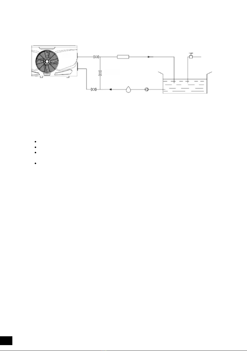
3.3 Piping Installation illustration
Outlet valve Chlorinator Water Valve
Sand lter or other type lter
Water pumpWater inletInlet valve
Water supply
Swimming pool
Bypass valve
3.4 Installation of a check valve
When using automatic chlorine and pH dosage systems, it is of uttermost importance to protect the heat
pump from high concentrations of these chemicals that could corrode the heat exchanger Therefore,
such systems should add the chemicals in the conduits located DOWNSTREAM of the heat pump and
it is recommended to install a check-valve in order to prevent back-ow when there is no water circulation.
Damage to the heat pump caused by disregarding any of these recommendations will invalidate the warranty.
3.5 Electrical Wiring
Important - Although the heat pump is electrically isolated from the rest of the unit, this only
prevents the passage of electricity to or from the pool water. Grounding the unit is still required
to protect yourself from short circuits inside the unit. Make for adequate ground connection.
Check if the electrical mains voltage corresponds with the operating voltage of the heat pump prior to
.
hooking up the unit. It is recommended to use a separate fuse (C-curve) as well as adequate wiring
(see table below). Connect the electrical wires with the terminal block labeled 'TO POWER SUPPLY'
Next to this connection, there is a second terminal block labeled 'TO PUMP', to which the lter pump
(max. 5A/240V) or an electrical relay for a ltration pump can be connected. This connection makes it
possible to control lter pump operation with the heat pump.
However, we do not recommend that you wire the pool circulation pump to the heat pump.Run separate
power supplies to the heat pump and the pool circulation pump. This allows the pool circulation pump to
be put on a time clock and operated for the required time to give adequate ltration for the pool and also
the pool circulation pump can be manually operated when required to backwash the lter etc.
10

PB25Y/32 10
12
20
20
22
25
7.2
9
16
17.5
19
21.5
2.5mm2
2.5mm2
2
2
2
2
4mm
4mm
4mm
4mm
*M inimal fuse
230V~/ 1 Ph/ 50Hz
230V~/ 1 Ph/ 50Hz
230V~/ 1 Ph/ 50Hz
230V~/ 1 Ph/ 50Hz
230V~/ 1 Ph/ 50Hz
230V~/ 1 Ph/ 50Hz
3.6 Initial start-up of the Unit
NOTE- In order for the unit to heat the pool or spa, the lter pump must be running to circulate water
through the heat exchanger.
Start up Procedure - After installation is completed, you should follow these steps:
Turn on your lter pump. Check for water leaks and verify ow to and from the pool.
Turn on the electrical power supply to the heat pump, then press the key ON/OFF of wire controller, It
should start in several seconds.
After running a few minutes make sure the air leaving the fan opening of the unit is cooler (between 5-10°C)
With the unit operating turn the lter pump off. The unit should also turn off automatically,
Allow the unit and pool pump to run 24 hours per day until desired pool water temperature is reached.
When the desired pool water temperature reaches the setting, the unit just shuts off. The unit will now
automatically restart (as long as your lter pump is running) when the pool temperature drops more than
2°C below set temperature.
Time Delay- The unit is equipped with a 3-minute built-in solid state restart delay included to protect
control circuit components and to eliminate restart cycling and contactor chatter.
This time delay will automatically restart the unit approximately 3 minutes after each control circuit
interruption. Even a brief power interruption will activate the solid state 3 minute restart delay and prevent
the unit from starting until the 5 minute countdown is completed. Power interruptions during the delay
period will have no effect on the 3 minute countdown.
3.7 Condensation
Since the Heat pump cools down the air about 5°C, water may condense on the ns of the evaporator.
If the relative humidity is very high, this could be as much as several liters an hour. The water will run
down the ns into the base pan and drain out through the barbed plastic condensation drain tting on the
side of the base pan.
This tting is designed to accept 20mm clear vinyl tubing which can be pushed on by hand and run to a
suitable drain. It is easy to mistake the condensation for a water leak inside the unit.
TIP:
A quick way to verify that the water is condensation is to shut off the unit and keep the pool pump running.
If the water stops running out of the base pan it is condensation
AN EVEN QUICKER WAY IS TO TEST THE DRAIN WATER FOR CHLORINE if there is no chlorine
present then it's condensation
,
.
.
-
,
Model NL- Voltage (V) Fuse (C-curve) Max current (A) Cable section*
11
PB35Y/32
PB50Y/32
PB60Y/32
PB70Y/32
PB80Y/32

4 Operation and Use(for ).
4 Display interface introduction.1
Num Meaning
1
2
3
4
5
6
7
ON OFF
Set
Time
/
Up
Down
Timer ON/OFF
Temperature display
Heating mode
Cooling mode
Automatic mode
Operating mode
Lock
Fan status
Time diasplay
8
9
10
11
12
13
14
1
2
3
1 2 45
6
7
8
91 0
11
1 2
13
14
Num Meaning
4.2 Operating instructions
1. When there is no key operation for 1min, the key and screen will be locked and the key operation is
invalid at this time
2. After locking, long press the “On/ Off” key to unlock.
,
4 2 1. . Key unlock
lock
12
NL-PB25Y~PB70Y/32

4 2 2. . Power On/ Off
In the unlocked state, press and hold the “On/ Off ” key for 2 seconds to switch “On / Off ”
Standby Interface Main Interface
4 2 3. . Switching the operating mode
In the main interface, press “Set” key to switch the working mode of the machine:
Eco Heating Silent Heating Boost Heating Eco Cooling Silent Cooling
Boost Cooling Auto.
nE: ECO
LO: SILIENT
HI: BOOST
AUTO COOL HEAT
Short press to switch
operation mode
Silent heating mode Boost Heating mode
4 2 4 Temperature adjustment. .
In the main interface of the startup, press the key or key, the set temperature will ash, press
the key or adjust the gure, press the key to conrm, and press the key back to home
page.
“ ” “ ”▲ ▼
“ ” “ ” “ ” “ ”▲ ▼
On the setting temperature setting interface, if there is no key operation for 30 seconds, the current
setting temperature value will be automatically conrmed and the screen will return to the main interface.
Setting
Set temperature
13

Parameter Code
T1
T2
T3
T4
T5
T6
T7
T8
T9
T10
T11
Ft
Fr
1F
2F
od
Pr
dF
OIL
r2
STF
Pu
AH
Ad
AL
dcU
dcC
AcU
AcC
HE1
HE2
HE3
HE4
Pr
Sr
RemarksParameter name
Exhaust gas temperature
Return air tempera ture
Inlet water temper ature
Water temperature
Outdoor coil temperature
Outdoor a mbient temperature
Reserved, please ignore
Actual fr equency
Opening d egree of main EEX valve
Reserved, please ignore
Reserved,
please
ignore
Reserved, please ignore
DC bus voltage
Inverter compressor current (A)
Reserved, please ignore
15

4 2 5 Time adjustment. .
Long press for 3 seconds
icker icker icker
Short press to switch hour /minute setting Adjust numbers
In the main interface, press the key to enter the real-time clock setting interface. The clock hour and
minute ash together.
In the real-time clock setting interface, press the key once, the digits in the hour part will ash, and
the minute part will stop ashing. At this time, press the key or key to set the hour of the real-
time clock
After setting the hour part, press the key again, the digits in the minute part will ash, and the hour
part will stop ashing. At this time, press the key or key to perform the minutes of the real-
time clock Settings.
“ ”
“ ”
“ ” “ ”▲ ▼
“ ”
“ ” “ ”▲ ▼
“ ”
“ ”
After the minute part is set press the key again to conrm the real-time clock setting and return to
the main
In the real-time clock setting interface press the key once to conrm the current real-time clock
setting value and return to the main interface
In the real-time clock setting interface, if there is no key operation for 30 seconds then conrm the
current real-time clock setting value and return to the main interface.
,
,
,
.
4 2. .6 Running parameter query
Press and hold the key for 3 seconds to enter, and then press the and keys to scroll up and
down through the pages.
“ ” “ ” “ ”▲ ▲ ▼
Press and hold for 3 seconds to enter the query status parameters
Short press to query other parameters
① ②
①
②
14

4.3 Error codes and troubleshooting
When the machine displays the following code, the machine may be in a protected or faulty state. You
can troubleshoot according to the following suggestions.
Code
E01
E05
E09
E13
E17
E18
E19
E20
E21
E22
E23
E24
E25
E26
E27
E28
P01
P02
P06
P10
P11
P15
Code
P23
P24
P25
P26
P27
r01
r02
r03
r04
r05
r06
r07
r08
r09
r10
r11
r14
r15
r16
r17
r18
r19
Fault description
Exhaust temperature failure
Coil temperature failure
Return air temperature failure
Cooling coil temperature failure
Return water temperature failure
Water temperature failure
Inlet water temperature failure
Hot water tank temperature failure
Communication fail
Ambient temperature failure
Limited time lock
Indoor temperature failure
Water ow switch failure
EEPROM error indication
Water protection
High pressure protection
Low pressure protection
Phase sequence protection
Exhaust temperature protection
Fault description
Compressor failed to start
Compressor speed feedback abnormal
Emergency stop
IPM module overheating protection
Overcurrent protection
U-phase overcurrent protection
Phase V overcurrent protection
W-phase overcurrent protection
DC voltage overvoltage protection
Low temperature protection during defrosting
Fan overload protection
Module board failure
DC voltage under voltage protection
W-phase phase error protection
U-phase phase shift fault
V-phase phase shift fault
W-phase phase shift fault
Compressor stall protection
Compressor speed abnormal protection
Communication failure between the adapter board
and the outdoor board
Heating return water temperature is too high
protection
Communication failure between outdoor board and
driver board
Excessive temperature difference between inlet
and outlet water
Low ambient temperature protection or low
ambient temperature reduced cooling
Refrigeration outdoor coil temperature is too
high for shutdown protection
16

Low temperature protection during defrosting
Fault description
Cooling undercooling protection
Standby frost protection
Electric heating overheating protection
Press current protection
Code
P16
P17
P18
P19
P23
Code
r20
r21
r22
r23
r24
Fault description
Compressor rotor stuck
Partial PFC overcurrent protection
Partial PFC overvoltage protection
Partial PFC undercurrent protection
Partial PFC check AC voltage frequency error
2 The compressor does not start
When the compressor does not start, it may be due to the following reasons:
The machine is not turned on, please press the key to start the machine.
The water temperature has reached the set temperature, and the machine stops working. Wait for the
water temperature to change to a certain value and then restart the work automatically.
The machine is not enough for 3 minutes. Due to the compressor's own protection requirements, after
the shutdown, it is necessary to wait at least 3 minutes before restarting the compressor. This is a normal
protection measure.
The machine is in a fault or other protection state. For details, see the description in the table at point 3.
The fan is not running
3. The fan is not running
When the fan does not start, it may be due to the following reasons:
The machine is not turned on, please press the key to start the machine
If the water temperature has reached the set temperature or above, the machine stops heating. After
the water temperature drops, heating can be resumed automatically.
The machine is in a fault or other protection state. For details, see the description in the table at point 1.
.
5 Operation and Use(for ) .
5.1 Display interface introduction
SET R 00M WAT ER
1
2
3
3
1 2 4 5
6
7
9
12
14
1 3
15
11
10
8
1 6
1. Main interface
17
NL-PB80Y/32

Num Meaning Num Meaning
ON OFF/
Set
Time
Up
Down
Time display
Timer ON/OFF
Temperature display
Wi indicator
1
2
3
4
5
6
7
8
9
10
11
12
13
14
15
16
17
18
Automatic mode
Cooling mode
Heating mode
Cooling mode
Water pump indicator
Set temperature
Fan indicator
Lock
Fault indicator
5.2 Operating instructions
5.2.1 Key unlock
1. When there is no key operation for 1min, the key and screen will be locked, and the key operation is
invalid at this time .
2. After locking, long press the "On/ Off" key to unlock.
lock
S ET
5.2.2 Power on / off
In the unlocked state, press and hold the on/off key for 2 seconds to switch on / off.“ ”
S ETS ET
18

5.2.3
In the main interface, press “ Set key to switch the working mode of the machine:
Switch the operating mode
”
Cooling
Heating Heating
heating cooling
S ET S ET
5.2.4 Temperature adjustment
In the main interface of the startup, press the ▲ key or ▼ key, the set temperature will ash, press
the ▲ key or ▼ key to adjust the size, press the "function" key to conrm, and press the on/off key
Back to Home page.
On the setting temperature setting interface, if there is no key operation for 30 seconds, the current
setting temperature value will be automatically conrmed and the screen will return to the main interface.
“ ” “ ”
“ ” “ ” “ ”
SET
setting inlet
5.2.5 Time adjustment
In the main interface, press the “Timer” key to enter the real-time clock setting interface. The clock hour
and minute ash together.
In the real-time clock setting interface, press the "Timer" key once, the digits in the hour part will ash,
and the minute part will stop ashing. At this time, press the “ ▲” key or “ ▼” key to set the hour of the
real-time clock .After setting the hour part, press the “Timer” key again, the digits in the minute part will
ash, and the hour part will stop ashing. At this time, press the “ ▲” key or “ ▼” key to perform the minutes
of the real-time clock Settings. After the minute part is set, press the “Timer” key again to conrm the
real-time clock setting and return to the main interface.
In the real-time clock setting interface, press the on/off key once to conrm the current real-time clock
setting value and return to the main interface.
“ ”
19

SET SET S ET
icker
icker
Short press Short press to switch
hour /minute setting
Adjust numbers
5.2.6 Timer setting
on/off
On the main interface, press and hold the “ ” key for 5 seconds to enter the setting of the group timer.
When entering the group timer interface, group 1 ashes, and there are total 3 timer groups.
When the group 1 ashes, press the “ ” key to enter the hour setting of “Timer On”, and the hour
digits ashes,press the “ ▲” key or “ ▼” Key, you can set the hour of “Timer On”.
After setting the hour of “Timer On”, press the “ ” key again to enter the minute setting of “Timer On”,
the minute digits ashes. Press the“ ▲” key or “ ▼” key to set the minute of “Timer On”.
After setting the hour and minute of “Timer On”, press the “ ” key again to enter the setting of “Timer
Off”. The setting method is the same as above. Press the “ ” key again to conrm the “Timer On/ Off”
of current group.
Press the “ ▲” key or “ ▼” key to enter the next group of “Timer On/ Off”. The same setting method as
above group 1.
If the timer group is valid, the group number will display on the main interface. In one timer group, it’s
invalid if “Time On” and “Timer Off” are the same. In the group timer interface, currently setting will be
saved and return to the main interface automatically, if there is no key operation for 30 seconds, In the
group timer interface, press the “ ” key once to conrm current setting and return to main interface.
① ②
SE T
1
2
3
SE T
1
icker
In the real-time clock setting interface, if there is no key operation for 30 seconds, then conrm the
current real-time clock setting value and return to the main interface.
20
This manual suits for next models
5
Table of contents
Other Nulite Heat Pump manuals
Popular Heat Pump manuals by other brands

DeDietrich
DeDietrich AWHP 4 MR user manual

Mitsubishi Electric
Mitsubishi Electric EHST20C- VM2C Operation manual

Mitsubishi Electric
Mitsubishi Electric Mr.SLIM PLA-A-BA6 Operation manual

Trane
Trane WSHP-DS-6 user manual

Ingersoll-Rand
Ingersoll-Rand A4AC4018A1000A Installer's guide

Northern Heatpump
Northern Heatpump NorthStarRA-WE-036 Installation & operating instructions