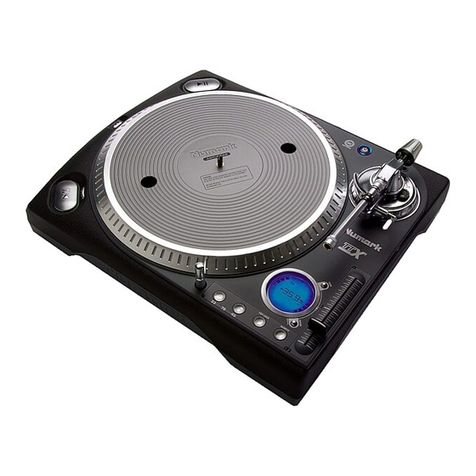
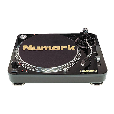
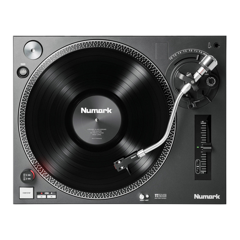
Numark TTX USB Technical document

Quick Start Owner’s Manual
ENGLISH (3-11)
Manual de inicio rápido del usuario
ESPAÑOL (12-20)
Guide d’utilisation simplifié
FRANÇAIS (21-29)
Schnellbedienungsanleitung
DEUTSCH (30-38)
Manuale rapido di utilizzazione
ITALIANO (39-47)


3
Quick Start Owner’s Manual
BOX CONTENTS
1. TTXUSB with Straight Tonearm
2. Anti-Drag Aluminum Platter
3. Slipmat
4. Headshell
5. 2.5g Weight for Headshell
6. Target Light
7. 45 RPM Adapter
8. S-Shaped Tonearm
9. Counter Weight
10. Additional Counter Weight for
S-Shaped Tonearm
11. IEC Power Cable
12. RCA Cord
13. USB Cord
14. Service Tool

4
Quick Assembly Instructions
PLEASE READ THE SAFETY INSTRUCTION BOOKLET BEFORE USING THIS PRODUCT
1. Notice the locking pins shown. BE SURE THAT THE TURNTABLE IS NOT PLUGGED IN.
2. Match the inner motor to Figure 2.
3. Carefully place platter with holes aligned to base as shown
Connections
1. Tilt turntable upright as shown.
2. Connect R-RCA (red) audio cable from mixer or amplifier.
Connect L-RCA (white) audio cable from mixer or amplifier.
3. Connect only the supplied power cord and ensure that power setting switch is in the correct position
for your region.
4. If you would like to record audio directly to your computer, connect the included USB cord from the
TTXUSB to your computer’s USB port.
Note: Be sure not to pinch wiring under base.

5
Bottom Panel Features
1. Adjustable Rubber Dampening Feet:
When all of the feet of the turntable are completely tightened, the top flat surface of the turntable will
be at 85mm. Unscrewing these feet raises the turntable up to compensate for unleveled surfaces.
2. Carrying Handles:
These handles provide a secure grip so that the turntable may be comfortably transported.
3. Voltage Selector:
This switches the internal voltage transformer between 115V, 230V and 240V. The turntable should be
shipped with the proper voltage setting for your region. Check that the switch is in the proper voltage
before connecting the power cord to prevent damage to the turntable.
4. IEC Power Terminal:
This IEC Power Terminal can be used with any IEC power cable, but it is recommended that the
supplied IEC power cable be used. Be sure that any IEC power cable attached has proper clearance
underneath the unit not to pinch cable or break power jack.
5. RCA Output:
These stereo output jacks allow the turntable to be connected to a compatible device with a PHONO or
LINE level input.
6. Phono/Line Selector:
This switch should be set to the proper level depending on the type of input the turntable is connected
to. PHONO is used with traditional turntable inputs on older receivers or where PHONO is stated. LINE
level allows the TTXUSB to directly connect to modern electronic inputs such as computers, home
stereos, and mixers.
7. Gain:
This knob sets the level of the audio signal going through the USB port to your computer. Please
adjust the gain to a suitable level so the meters in your software application never hit the clip meter
(red).
8. USB Audio Output:
Use the included USB Cable to connect your turntable to your computer. Refer to the software
instruction guide for more information.

6
Tonearm Assembly
1. Counterweight/Ring and S-Weight:
The Counterweight is used to balance the head
shell and cartridge assembly so that the proper
amount of stylus pressure is applied to the
record. The S-Weight should be used in most
cases when the S-Shaped tube is used. It is
not needed for the straight arm and can be
stored below the counterweight in the top
cabinet while not in use.
2. Height Adjust Ring:
Turning this ring counter-clockwise raises the
tonearm up to 6mm to accommodate for
different slipmat thicknesses. This ring can not
be adjusted unless the Height Lock Lever (3) is
unlocked.
3. Height Lock Lever:
Turning this lever towards the direction of the
arrow (clockwise) unlocks the Height Adjust
Ring (2) so that the tonearm height can be
adjusted.
4. Anti-Skate Adjustment:
This knob is used to compensate for inward
tracking forces. See Tonearm Setup for more
details on its settings.
5. Secondary Tube Lock Collar:
This collar is used to secure the tonearm tubes
(straight or s-shaped) to the tonearm
assembly.
6. Arm Clip:
This specially designed arm clip secures the
tone arm while it is being transported or not in
use.
7. Tonearm Cueing System:
This feature allows the tone arm to be
positioned at a certain point above the record
and slowly engaged. When the lift lever is in
the up position the tone arm should rest on the
armrest. When the lift lever is lowered, the
tone arm is slowly lowered until the stylus is
resting on the record.
8. Tone Arm Lock Nut:
This aluminum nut is used to secure the head
shell and cartridge assembly to the tone arm
tube. See cartridge setup for more details.
WARNING: DO NOT OVERTIGHTEN LOCK COLLAR (5) OR THE LOCK NUT (8)!
CONNECTING ANYTHING OTHER THAN NUMARK ARMS TO THIS COLLAR MAY DAMAGE THE
INTERNAL PIN HEIGHTS OF THE CONTACTS!

7
Tonearm Setup
1. Install cartridge and raise the arm lift for cartridge/stylus protection.
2. Notice how the counterweight can be moved.
3. With the cueing system lift lever down, adjust the weight so entire tonearm assembly is freely
balanced.
4. Zero the scale on the weight by moving the black ring until “0” is aligned with the slot. The tonearm
assembly should still be balanced as shown in Figure 2.
5. Turn the counterweight until the desired weight in grams is met. (Most DJ cartridge specifications
range from 2.0g to 4.0g. Check cartridge manual for details)
Setting the Anti-Skate Adjustment
The Anti-Skate control is the knob shown on the last figure.
In most cases, the Anti-Skate should be set to its minimum setting. Anti-Skate compensates for inward
tracking forces that occur with certain cartridges when the stylus nears the center of the record. If the
turntable is experiencing excessive skipping during back-cueing and scratching while nearing the center
spindle, try increasing the Anti-Skate in the increments indicated on the dial. Start by adding small
increments; test its performance, then increase it as necessary.
The Anti-Skate control is primarily used for high quality recordings in conjunction with the tonearm cuing
system.
OPERATION NOTES
This turntable was designed to accommodate a variety of different mixing styles. Here are some general
operation guidelines to optimize the performance of the turntable.
•Use the included Slip Mat during record playback. This Slip Mat was designed to reduce friction
between the platter and the record to allow for rapid back cueing and efficient scratch play.
•Do not place the turntable on or near a speaker or subwoofer. This may cause unwanted noise
depending on the environment conditions.
•Always secure the tone arm using the Arm Clip when not in use. This can prevent stylus damage
and accidental tone arm engagement.
•To reduce needle skipping, follow the guidelines in the Tone Arm Setup section of this manual. Too
much weight on a cartridge may cause erratic skipping or stylus damage.

8
General Controls
1. Power Button: Turns on the turntable when pressed. It illuminates blue when the turntable is
switched on.
2. Start/Stop Buttons: Start and stop the turntable motor. Both buttons have the same function.
3. Platter: This turntable has a special edge design that has been optimized for "dragged" platter slow
downs. The pattern will appear to stand still when the Pitch Range is set to 0% and the Target Light
is being used.
4. Forward/Reverse Toggle: Switches the motor direction between forward and reverse.
5. Start Time Adjuster: Rotate to increase or decrease the startup time of the platter.
6. Braking Time Adjuster: Rotate to increase or decrease the stopping time of the platter.
7. Strobe Target Light and Power Jack: This aluminum light can be rotated depending on the head
shell position and the amount of light required on the vinyl record surface. The light strobes against
the platter edge making the pattern appear to stand still when the Pitch Range is at 0%.
8. Pitch Fader: This slide control allows the pitch of the playback to be changed. In the center position
the pitch is at 0%
9. Key Lock: This button locks the key of the music at the relative position of the Pitch Fader. This
processing effect is only available when the LINE output is used.
10. Quartz Button: This button locks the pitch at 0% (regardless of pitch fader position) using Quartz
Motor Control when engaged.
11. Torque Adjustment: Lightly press buttons 9 and 10 simultaneously to adjust the torque settings of
the platter. There are three settings for torque. “L” is low, “M” is medium, and “H” is high.
12. 33 and 45 RPM Buttons: These buttons control the RPM of the turntable platter. When both of the
33 and 45 RPM buttons are pressed simultaneously, the 78 RPM mode will engage.

9
Display Controls
The Display of the TTXUSB was developed to instantly provide usable feedback regardless of the turntable
orientation. Understanding its functions may improve your skill level.
1. Platter Direction Sensors: Whether the turntable platter is turning or stopped, these segments
indicate the direction of rotation. They move in pairs on opposite sides of the display.
NOTE: If the platter is removed while the turntable is powered on, the entire ring of
segments will flash indicating that the drive magnets have been pulled apart and the
motor has entered PROTECTION MODE. It is recommended that the turntable be powered
off after it enters PROTECTION MODE before replacing the platter.
2. Multi-Function Segment Indicators: Depending on the display mode, these Indicators may
provide pitch, BPM or motor settings. See the independent functions of the PITCH, BPM and MOTOR
CONTROLS for additional information.
3. BPM Button: Pressing this button will toggle the center section of the display between the current
pitch setting and an estimated beats per minute (BPM) reading. If this button is pressed and held for
2 seconds, the BPM counter will recalculate the BPM estimation. If the display is indicating a steady
"---" this means that the TTXUSB is calculating the BPM range OR it is unable to distinguish an
estimate. If the BPM estimation is a flashing "---" then this indicates that there is no audio being
processed.
4. Pitch versus BPM indicators: The
word PITCH and the PERCENTAGE
symbol are both active while the
display indicates the pitch setting. The
BPM indicator is only active when the
display is set to provide BPM
estimations.
5. Pitch Range Button: This button
toggles the pitch range between 10,
20 and 50% when pressed in
succession. If this button is pressed
and held for 2 seconds, the pitch
range will be set to 8% until the
button is pressed again. If this button
is pressed and held together with the
BPM Button (3), then the contrast of
the Display will be reduced until the
buttons are released.
6. Pitch Range Indicators: Depending
on the pitch range (8, 10, 20, 50%)
these indicators will be active. When
the pitch range is set to 8%, none of
these indicators are active.
7. RPM settings: The 33, 45 or 78
segments will be active for the
respective motor RPM mode.
8. Key Lock Indicator: This symbol
indicates that the onboard digital signal processors are correcting the KEY of the playback source.
NOTE: The KEY LOCK function can only be used while the output is set to LINE level.
9. Quartz Lock Indication: If the QUARTZ LOCK function (General Controls) is engaged, this
segment becomes active and the display will flash "- Q -" if the PITCH FADER is adjusted until the
QUARTZ LOCK function is deactivated.
10. Start Time Indicator: If this indicator is active while the motor is starting, it means that the
startup time has been adjusted using the Start Time Adjuster (General Controls)
11. Brake Time Indicator: If this indicator is active while the motor is stopping, it means that the stop
time has been adjusted using the Braking Time Adjuster (General Controls)
12. Contrast: Press both (3) and (5) simultaneously to cycle through contrast levels on the display.

10
Interchanging the Pitch Fader and
Button Cartridges
The TTXUSB unique design allows the
configuration of the PITCH FADER and BUTTON
CONTROLS to be interchanged depending on the
orientation of the turntable. In the event of
damage or excessive wear, these components
should only be replaced with NUMARK
COMPATIBLE PARTS. Check the nearest NUMARK
DEALER for additional information.
1. Turn the turntable off or unplug it from its
power source.
2. Remove the PITCH FADER KNOB and store
it in a safe place.
3. Use the included SERVICE TOOL to remove
the two screws that secure the PITCH
FADER CARTRIDGE PLATE. Once removed,
place these screws in a safe place.
4. Use the flat side of the SERVICE TOOL to
pry off the PITCH FADER CARTRIDGE PLATE
by inserting it into the cutaway at the
center of the plate and prying upwards
5. Use the included SERVICE TOOL to remove
the two screws that secure the BUTTON
CARTRIDGE PLATE. Once removed, place
these screws in a safe place.
6. Using the flat side of the SERVICE TOOL
again, pry off the BUTTON CARTRIDGE
PLATE by inserting it underneath the plate
and prying upwards (see picture.)
7. The cartridges may now be safely removed.
Begin this process by using the flat side of
the SERVICE TOOL to pry the PITCH FADER
CARTRIDGE out of the turntable (see
picture.) Once removed, detach the wiring
clip from the bottom of the cartridge.
8. Remove the Button Cartridge now by using
the SERVICE TOOL to pry out the cartridge
from the turntable. Once removed, detach
the wiring clip from the bottom of the
cartridge (see picture.)
9. The cartridges may now be safely
interchanged. Find the WIRING CLIP for the
PITCH FADER CARTRIDGE and connect it to
the bottom of the cartridge (see picture.)
10. Reinsert the PITCH FADER CARTRIDGE into
the desired bay of the turntable. Take
utmost care NOT to pinch the unused
harness underneath the cartridge. If
inserted correctly, the cartridge should rest
firmly in the bay.
11. Find the WIRING CLIP for the BUTTON
CARTRIDGE and connect it to the bottom of
the cartridge (see picture.)
12. Reinsert the BUTTON CARTRIDGE into the
desired bay of the turntable. Take utmost
care NOT to pinch the unused harness
underneath the cartridge. If inserted
correctly, the cartridge should rest firmly in
the bay.
13. Re-secure the BUTTON CARTRIDGE PLATE
and the FADER CARTRIDGE PLATE by
inserting the tabbed sides into the turntable
first.
14. Use the included SERVICE TOOL to tighten
the four screws that secure the plates to the
turntable body. Do not over tighten these
screws.
15. Reinstall the PITCH FADER knob and power
the turntable on.
11
OTHER IMPORTANT NOTES
Please read these precautionary notes to insure a complete understanding and long life of this DJ turntable.
•Unnecessarily removing the platter may cause damage to the magnet mounting structure, the motor or the
platter resulting in undesired performance. The turntable should ALWAYS be powered off before the
turntable platter is removed for any reason.
•Unnecessarily "interchanging" tonearm tubes may cause premature wear to components of the tonearm
assembly or the tonearm tubes. Interchange tubes only on an "as needed" basis.
•Turning off the turntable while the output is set to LINE level or while the SPDIF output is in use will result in
an absence of audio. Keep this in mind during use - if the "motor off" effect is desired effect, it is
recommended that the BRAKE MOTOR CONTROL be adjusted.
•Do not attempt to adjust or tighten any tonearm components. Undesirable performance may be a result of an
improperly adjusted tonearm or worn cartridge.
•Never interchange tonearm tubes while the turntable is powered on.
•Any attempt to "customize" your turntable beyond interchanging the tonearm tubes is not recommended and
may result in PERMANENT DAMAGE to the turntable and/or a VOIDED WARRANTY.
SOFTWARE
The TTXUSB connects directly to your computer to turn your treasured vinyl recordings into digital music. We have
included several software packages to aid you in converting your vinyl recordings. You should install one of the
following applications to take advantage of computer recording:
EZ Vinyl/Tape Converter* (PC only) is the quickest and easiest way
to turn your recordings into digital media. EZ Vinyl/Tape Converter
conveniently saves your recordings in your iTunes** library. Novice
users may find this application preferable. On the CD, we have included
a handy Software Quickstart Guide with step-by-step instructions on
software installation and operation.
EZ Audio Converter (Mac only) is a basic converter application for Mac
OS X and is ideal for novice users. Please refer to the included Software
Quickstart Guide for step-by-step instructions on software installation
and operation.
Audacity (PC and Mac) is intended for the advanced user. This application allows for advanced audio editing
and processing, such as normalization, noise removal, 78 RPM speed conversion, and automatic track
separation. The Audacity Software Guide can be found on the included CDs – please refer to this guide as
you are working with Audacity.
To install the software: simply insert the included CD into your computer and follow the on-screen instructions.
After you finish converting your vinyl, you can then burn to CD or load onto portable media devices.
TTXUSB Specifications
Turntable Section:
Motor:
Start Time:
Braking System:
Platter:
Speeds:
Wow & Flutter:
Pitch Range:
Rumble:
Torque:
Direct Drive – 16 Pole, 3 phase
0-33.33 RPM in 0.2 seconds
9 Step Electronic Servo Brake
Dampened Aluminum Die-cast
Low Friction Design.
33.33, 45, and 78 RPM
<0.15% WRMS (JIS C5521)
Digitally controlled by internal
quartz clock.
±8%, ±10%, ±20%, and ±50%
-58dB (IEC 98A Unweighted)
-79dB (IEC 98A Weighted)
H : 4.7 kgfcm
constant torque : 3.7kgfcm
instant torque : 4.7 kgfcm
M : 3.7 kgfcm
constant torque : 2.7kgfcm
instant torque : 3.7 kgfcm
L : 2.5 kgfcm
constant torque : 1.1kgfcm
instant torque : 2.5 kgfcm
Tonearm Section:
Type:
Height Range:
Cue System:
Balance Weight:
General:
Dimensions:
Weight:
Power Consumption:
USB Audio Interface:
Locking collar based
interchangeable tube system. Die-
cast Aluminum
3-Bearing Construction
0.0 – 6.0 mm.
Dampened Lift Lever,
Arm Rest and Arm Clip
7.0 gram S-weight
75 gram Aluminum Plated
Counterweight
w/ 0.0 – 3.5 gram range scale
370mm(W) by 460mm(D) by
135mm(H)
27.7 lbs (12.6 kg)
65 Watts
USB 1.1 compatible
* A version of EZ Vinyl/Tape
Converter with Gracenote
MusicID is available for
download at your product’s
page at www.numark.com.
** iTunes and iPod are
trademarks of Apple, Inc.,
registered in the U.S.A. and
other countries.

12
Manual de inicio rápido del usuario
CONTENIDO DE LA CAJA
1. TTXUSB con brazo de lectura
recto
2. Plato de aluminio anti-arrastre
3. Alfombrilla
4. Portacápsulas
5. Contrapeso de 2.5 g para
portacápsulas
6. Luz de iluminación de cabezal
7. Adaptador de 45 rpm
8. Brazo de lectura en forma de
“S”
9. Contrapeso
10. Contrapeso adicional para el
brazo de lectura en forma de
“S”
11. Cable de alimentación IEC
12. Cordón RCA
13. Cordón USB
14. Herramienta de servicio

13
Instrucciones de ensamblaje rápido
POR FAVOR LEA LAS INSTRUCCIONES DEL FOLLETO DE SEGURIDAD ANTES DE UTILIZAR ESTE
PRODUCTO
1. Observe los pasadores de bloqueo que se muestran. ASEGÚRESE QUE EL GIRADISCOS NO ESTÉ
ENCHUFADO.
2. Haga concordar el motor interior con la Figura 2.
3. Alinee los agujeros del plato cuidadosamente con la base, como se muestra aquí.
Conexiones
1. Incline el giradiscos verticalmente como se muestra aquí.
2. Conecte el cable de audio R-RCA (derecho rojo) del mezclador o amplificador.
Conecte el cable de audio L-RCA (izquierdo blanco) del mezclador o amplificador.
3. Sólo conecte el cable de alimentación incluido y asegúrese que el interruptor de ajuste de
alimentación esté en la posición correcta para su región.
4. Use el cable USB incluido para conectar su giradiscos a su computadora.
Nota: Asegúrese de no apretar el cableado debajo de la base.

14
Características del panel inferior
1. Patas de amortiguación de goma:
Cuando todas las patas del giradiscos estén completamente apretadas, la superficie plana superior del
giradiscos estará a los 85 mm. Cuando destornilla estas patas se eleva el giradiscos para compensar
las superficies desniveladas.
2. Asas de transporte:
Estas asas dan un agarre seguro para que el giradiscos pueda transportarse de manera cómoda.
3. Selector de voltaje:
Este selector hace que el transformador de voltaje interno conmute entre 115 V, 230 V y 240 V. El
giradiscos debe ser despachado con el ajuste de voltaje adecuado para su región. Revise que el
interruptor esté ajustado al voltaje adecuado antes de conectar el cable de alimentación para prevenir
daños al giradiscos.
4. Terminal de alimentación IEC:
Este terminal de alimentación IEC puede usarse con cualquier cable de alimentación IEC, pero le
recomendamos que use el cable de alimentación IEC incluido. Asegúrese de que cualquier cable de
alimentación IEC conectado tenga suficiente espacio debajo de la unidad para que no se apriete el
cable o se quiebre el enchufe de alimentación.
5. Salida RCA:
Estos enchufes de salida estéreo permiten conectar el giradiscos a un dispositivo compatible con una
entrada de nivel fonográfico o de línea.
6. Selector de nivel de línea/fonográfico:
Este interruptor debe ajustarse al nivel correcto dependiendo del tipo de salida al cual esté conectado
el giradiscos. Se usa la entrada fonográfica PHONO con las entradas de giradiscos tradicionales en
receptores más antiguos o donde se requiera PHONO. El nivel de línea LINE permite que el TTXUSB se
conecte directamente a las entradas de equipos electrónicos modernos como computadoras, estéreos y
mezcladores.
7. Perilla de ganancia:
Ajusta el nivel de audio USB.
8. Salida da audio USB
Use el cable USB incluido para conectar su giradiscos a su computadora. Consulte la guía de
instrucciones de software antes de enchufar el giradiscos.

15
Ensamblaje del brazo de lectura
1. Contrapeso/anillo y peso en forma de “S”:
El contrapeso se usa para balancear el
ensamblaje del portacápsulas y la cápsula para
que se le aplique la cantidad adecuada de
presión de la púa al disco. El peso en forma de
“S” se debe usar en la mayoría de los casos
cuando se usa el tubo en forma de "S". No se
necesita para el brazo recto y puede
almacenarse debajo del contrapeso en el
gabinete superior mientras no sea usado.
2. Anillo de ajuste de altura:
Gire este anillo en el sentido opuesto a las
agujas del reloj para elevar el brazo de lectura
hasta 6 mm para acomodar diferentes
espesores de alfombrillas. Este anillo no se
puede ajustar a menos que la manija de
bloqueo de altura (3) esté desbloqueada.
3. Manija de bloqueo de altura:
Gire esta manija en el sentido de la flecha
(sentido de las agujas del reloj) para
desbloquear el anillo de ajuste de altura (2) a
fin de que se pueda ajustar la altura del brazo
de lectura.
4. Ajuste Anti-Skate (anti-deslizamiento):
Este botón se usa para compensar las fuerzas
de tracción hacia adentro. Lea Instalación del
brazo de lectura para conocer más detalles
acerca de este ajuste.
5. Anillo de bloqueo del tubo secundario:
Este anillo se usa para asegurar los tubos del
brazo de lectura (recto o en forma de “S”) al
montaje del brazo de lectura.
6. Clip del brazo:
Este clip diseñado especialmente fija el brazo
mientras se está transportando o mientras no
se usa.
7. Sistema de señalización del brazo de
lectura:
Esta característica permite que el brazo de
lectura sea posicionado en un punto específico
sobre el disco y que descienda lentamente.
Cuando la palanca elevadora está arriba, el
brazo de lectura debe sostenerse en el soporte
del brazo. Cuando baja la palanca, se baja el
brazo de lectura de manera lentamente hasta
que la púa se apoye sobre el disco.
8. Tuerca de fijación del brazo:
Esta tuerca de aluminio se usa para fijar el
ensamblaje del portacápsulas y la cápsula al
tubo del brazo. Consulte la Instalación de la
cápsula para conocer más detalles.
ADVERTENCIA: ¡NO SOBREAPRIETE EL ANILLO DE BLOQUEO (5) O TUERCA DE FIJACIÓN DEL
BRAZO ! (8)
¡SI SE CONECTAN A ESTE ANILLO BRAZOS QUE NO SEAN DE NUMARK PODRÍAN DAÑARSE LAS
ALTURAS DE LOS PASADORES INTERNOS DE LOS CONTACTOS!

16
Instalación del brazo de lectura
1. Instale la cápsula y levante el elevador del brazo para protección de la cápsula/púa.
2. Note cómo se puede mover el contrapeso.
3. Con la palanca elevadora del sistema de señalización, ajuste el peso para que todo el montaje del
brazo de lectura esté equilibrado libremente.
4. Ponga la escala en posición de cero para el peso moviendo el anillo negro hasta alinear el "0" con la
ranura. El montaje del brazo de lectura debe seguir equilibrado como se muestra en la Figura 2.
5. Gire el contrapeso hasta que se alcance el peso deseado en gramos. (La mayoría de las
especificaciones de la cápsula de DJ varían de 2.0 a 4.0 g. Verifique los detalles en el manual de la
cápsula).
Ajuste del Anti-Skate (anti-deslizamiento)
El control de anti-deslizamiento es el botón que se muestra en la última figura.
En la mayoría de los casos, el Anti-Skate debe ser ajustado a su ajuste mínimo. El anti-skate compensa
las fuerzas de tracción hacia adentro que ocurren con ciertas cápsulas cuando la púa se acerca al centro
del disco. Si el giradiscos experimenta excesivos saltos en los retrocesos rápidos y rayaduras cuando se
acerca al eje central, intente aumentar el Anti-Skate en los incrementos indicados en el botón. Empiece
agregando incrementos pequeños; pruebe su rendimiento y luego auméntelos como considere necesario.
El control de anti-deslizamiento se usa mayormente para las grabaciones de alta calidad junto con el
sistema de señalización del brazo de lectura.
NOTAS SOBRE EL FUNCIONAMIENTO
El giradiscos fue diseñado para admitir una variedad de diferentes estilos de mezcla. He aquí algunas
pautas de funcionamiento generales para optimizar el rendimiento del giradiscos.
•Use la alfombrilla incluida durante la reproducción de la grabación. Esta alfombrilla fue
diseñada para reducir la fricción entre el plato y el disco a fin de permitir una señalización
hacia atrás rápida y una reproducción con scratch eficiente.
•No coloque el giradiscos sobre o cerca de un altavoz o altavoz de graves (subwoofer). Puede
causarse un ruido no deseado dependiendo de las condiciones ambientales.
•Siempre asegure el brazo de lectura usando el clip del brazo mientras no se use. Esto puede
prevenir daños a la púa y el funcionamiento accidental del brazo de lectura.
•Para reducir los saltos de la púa, siga las directrices que se incluyen en la sección de
Instalación del brazo de lectura en este manual. Un peso excesivo sobre la cápsula puede
causar que la púa salte irregularmente o que sea dañada.

17
Controles Generales
1. Botón de encendido: Enciende el giradiscos cuando se presiona. Se ilumina de color azul cuando
está encendido el giradiscos.
2. Botones Start/Stop: Inician y paran el motor del giradiscos. Ambos botones tienen la misma
función.
3. Plato: Este giradiscos cuenta con un diseño de vanguardia especial que ha sido optimizado para
desacelerar con “arrastre”. El patrón se verá inmóvil cuando el rango del pitch esté ajustado al 0% y
cuando se use la luz de iluminación.
4. Conmutador de adelante/atrás: Cambia el sentido del motor hacia adelante y atrás.
5. Ajustador del tiempo de inicio (Start): Gírelo para aumentar o disminuir el tiempo de inicio del
plato.
6. Ajustador del tiempo de frenado: Gírelo para aumentar o disminuir el tiempo de parada del
plato.
7. Luz estroboscópica y enchufe de alimentación: Esta luz de aluminio puede girarse
dependiendo de la posición del portacápsulas y la cantidad de luz que se requiere sobre la superficie
del disco de vinilo. La luz parpadea de manera estroboscópica contra el borde del plato haciendo
que parezca detenido cuando el rango del pitch esté al 0%.
8. Pitch Fader: Este deslizador permite que se cambie el pitch de la reproducción. En la posición
central, el pitch está al 0%.
9. Key Lock (bloqueo de tono): Este botón bloquea el tono de la música en la posición relativa del
fader de pitch. Este efecto de procesamiento sólo está disponible cuando se usa la salida de la línea
(LINE).
10. Botón de cuarzo: Este botón bloquea el pitch al 0% (no importa la posición del fader de pitch)
usando el control del motor de cuarzo cuando está acoplado.
11. Ajuste del torque: Presione los botones 9 y 10 ligeramente y simultáneamente para ajustar las
selecciones del torque del plato. Hay tres ajustes del torque. “L” es bajo, “M” mediano y “H” alto.
12. Botones de 33 y 45 RPM: Estos botones controlan las RPM del plato del giradiscos. Cuando
ambos botones de 33 y 45 RPM se presionan simultáneamente, se activará el modo de 78 RPM.

18
Controles de visualización
La visualización del TTXUSB fue desarrollada para brindar una retroalimentación utilizable
instantáneamente independientemente de la orientación del giradiscos. Conocer sus funciones puede
mejorar su nivel de especialización.
1. Sensores del sentido del plato: Aunque el plato del giradiscos esté girando o esté parado, estos
segmentos indican el sentido de giro. Se mueven en pares a los lados opuestos del visualizador.
NOTA: Si se retira el plato mientras el giradiscos está encendido, todos los segmentos
parpadearán indicando que los imanes de transmisión han sido separados y que el motor
ha entrado en el MODO DE PROTECCIÓN. Le recomendamos que apague el giradiscos
después que entre en el MODO DE PROTECCIÓN antes de volver a colocar el plato.
2. Indicadores de segmentos multifunciones: Dependiendo del modo de visualización, estos
indicadores pueden dar los ajustes del pitch, del BPM o del motor. Vea las funciones independientes
de PITCH, BPM y de los CONTROLES DEL MOTOR para más información.
3. Botón de BPM: Presione este botón para conmutar la sección central del visualizador entre el
ajuste actual del pitch y una lectura de los ritmos por minuto (BPM). Si presiona el botón y lo
mantiene presionado por 2 segundos, el contador de BPM recalculará la aproximación de los BPM. Si
el visualizador indica “---“ constante, significa que el TTXUSB está calculando el rango de los ritmos
por minuto (BPM) O que no puede distinguir una aproximación. Si el cálculo de los BPM es un “---“
destellante, indica que no se está procesando ningún audio.
4. Pitch en función los indicadores
de BPM (ritmos por minuto): La
palabra PITCH y el símbolo de
porcentaje (PERCENTAGE) están
ambos activos mientras que el
visualizador indica el ajuste del pitch.
El indicador de BPM está activo
solamente cuando el visualizador está
ajustado para dar estimaciones
aproximadas de los ritmos por
minuto.
5. Botón de rango de pitch: Este
botón alterna el rango de pitch entre
el 10, 20 y 50% cuando se presiona
en sucesión. Si se presiona y
mantiene presionado este botón por 2
segundos, el rango del pitch será
ajustado al 8% hasta que el botón se
presione otra vez. Si se presiona y
mantiene presionado este botón junto
con el botón de BPM (3), se reducirá
el contraste del Visualizador hasta que
se suelten los botones.
6. Indicadores de rango de pitch:
Estos indicadores estarán activos en
función del rango de pitch (8, 10, 20 y
50%). Ningunos de estos indicadores
están activos cuando el rango de pitch
está ajustado al 8%.
7. Ajustes de RPM: Los segmentos de
33, 45 ó 78 estarán activos para el
modo de RPM del motor respectivo.
8. Indicador de bloqueo de tono (Key Lock): Este símbolo indica que los procesadores de señales
digitales instalados están conectando el tono (KEY) de la fuente que se reproduce.
NOTA: La función KEY LOCK se puede usar solamente cuando la salida está ajustada al
nivel de línea (LINE).
9. Indicación de bloqueo de cuarzo (Quartz Lock): Si la función de QUARTZ LOCK (Controles
generales) está activada, este segmento se activa y el visualizador destellará “- Q -" si el PITCH
FADER está ajustado, hasta que la función del QUARTZ LOCK esté desactivada.
10. Indicador de tiempo de arranque: Si este indicador está activo mientras el motor se está
arrancando, significa que el tiempo de arranque ha sido ajustado usando el ajustador de tiempo de
arranque (Controles generales).
11. Indicador de tiempo de frenado: Si este indicador está activo mientras el motor se está parando,
significa que el tiempo de parada ha sido ajustado usando el ajustador de tiempo de frenado
(Controles generales).
12. Contraste: Presione (3) y (5) simultáneamente para realizar un ciclo por los niveles de contraste
en el visualizador.

19
Intercambio de las cápsulas de Pitch Fader
y de botones
El diseño único del TTXUSB permite que las
configuraciones del PITCH FADER y los
CONTROLES DE BOTONES sean intercambiados
en función de la orientación del giradiscos. En el
evento de daños o desgastes excesivos, estos
componentes se deben reemplazar solamente con
PARTES COMPATIBLES CON LAS PARTES DE
NUMARK. Consulte al VENDEDOR DE NUMARK
más cercano para obtener más información.
1. Apague el giradiscos o desenchúfelo de su
fuente de alimentación.
2. Retire la PERILLA DE PITCH FADER y
guárdela en un lugar seguro.
3. Use la HERRAMIENTA DE SERVICIO incluida
para retirar dos tornillos que fijan la PLACA
DE LA CÁPSULA DEL PITCH FADER. Después
de retirarlos, coloque estos tornillos en un
lugar seguro.
4. Use el lado plano de la HERRAMIENTA DE
SERVICIO para extraer la PLACA DE LA
CÁPSULA DEL PITCH FADER insertándola en
la ranura en el centro de la placa y haciendo
palanca hacia arriba.
5. Use la HERRAMIENTA DE SERVICIO incluida
para retirar dos tornillos que fijan la PLACA
DE LA CÁPSULA DE BOTONES. Después de
retirarlos, coloque estos tornillos en un
lugar seguro.
6. Usando el lado plano de la HERRAMIENTA
DE SERVICIO otra vez, extraiga la PLACA
DE LA CÁPSULA DE BOTONES insertándola
debajo de la placa y haciendo palanca hacia
arriba (vea la foto).
7. Ahora puede retirar las cápsulas con
seguridad. Comience este proceso usando el
lado plano de la HERRAMIENTA DE
SERVICIO para extraer la CÁPSULA DEL
PITCH FADER y sacarla del giradiscos (vea
la foto). Después de retirarla, desmonte el
clip de alambre de la parte inferior de la
cápsula.
8. Retire la cápsula de botones usando la
HERRAMIENTA DE SERVICIO para extraer la
cápsula del giradiscos. Después de retirarla,
desmonte el clip de alambre de la parte
inferior de la cápsula.
9. Ahora puede intercambiar las cápsulas con
seguridad. Busque el CLIP DE ALAMBRE
para la CÁPSULA DEL PITCH FADER y
conéctelo a la parte inferior de la cápsula
(vea la foto).
10. Vuelva a insertar la CÁPSULA DEL PITCH
FADER en el compartimiento deseado del
giradiscos. Tome mucho cuidado de NO
apretar el arnés que no se usa debajo de la
cápsula. Si se inserta correctamente, la
cápsula debe apoyarse firmemente en el
compartimiento.
11. Busque el CLIP DE ALAMBRE para la
CÁPSULA DE BOTONES y conéctelo a la
parte inferior de la cápsula (vea la foto).
12. Vuelva a insertar la CÁPSULA DEL BOTÓN al
conector deseado del giradiscos. Tome
mucho cuidado de NO apretar el arnés que
no se usa debajo de la cápsula. Si se inserta
correctamente, la cápsula debe apoyarse
firmemente en el compartimiento.
13. Vuelva a asegurar la PLACA DE LA CÁPSULA
DE BOTONES y la PLACA DE LA CÁPSULA
DEL FADER insertando los lados con
pestañas en el giradiscos primero.
14. Use la HERRAMIENTA DE SERVICIO incluida
para apretar los cuatro tornillos que fijan las
placas al cuerpo del giradiscos. No
sobreapriete estos tornillos.
15. Vuelva a instalar la perilla del PITCH FADER
y encienda el giradiscos.

20
OTRAS NOTAS IMPORTANTES
Por favor lea las notas de precauciones para asegurar un conocimiento completo y una larga vida de este giradiscos
para DJ.
•Retirar el plato sin necesidad puede causar daños a la estructura de montaje del imán, al motor o al plato,
que pueden ocasionar su funcionamiento incorrecto. El giradiscos debe apagarse SIEMPRE antes de retirar el
plato del mismo por cualquiera razón.
•“Intercambiar” los tubos del brazo de lectura sin necesidad puede causar el desgaste prematuro de los
componentes del montaje o de los tubos del brazo de lectura. Intercambie los tubos sólo cuando sea
necesario.
•Apagar el giradiscos mientras la salida está ajustada al nivel de LÍNEA o mientras se está usando la salida
SPDIF producirá la ausencia de audio. Recuerde esto durante el uso —si se desea el efecto de “motor
apagado”, le recomendamos que ajuste el CONTROL DE FRENO DEL MOTOR.
•No intente ajustar o apretar cualquier ningún del brazo de lectura. El funcionamiento incorrecto puede ser el
resultado de un brazo de lectura mal ajustado o de una cápsula desgastada.
•Nunca intercambie los tubos del brazo de lectura mientras el giradiscos está encendido.
•No se recomienda ningún intento de "personalizar" su giradiscos más allá de cambiar los tubos del brazo de
lectura, puesto que puede resultar en DAÑO PERMANENTE al giradiscos y/o en una GARANTÍA INVÁLIDA.
SOFTWARE
TTXUSB se conecta directamente a su computadora para convertir sus valiosos vinilos en música digital. Hemos
incluido varios paquetes de software para ayudarle a convertir sus grabaciones de vinilo. Debe instalar una de las
siguientes aplicaciones para aprovechar la función de grabación de su computadora:
EZ Vinyl/Tape Converter* (sólo PC) es la forma más rápida y
fácil de convertir las grabaciones en medios digitales. Este
software guarda convenientemente sus grabaciones en la
biblioteca de iTunes**. Es posible que los usuarios novicios
prefieran esta aplicación. En el CD, incluimos una práctica Guía de
inicio rápido con instrucciones paso a paso sobre la instalación y la
operación del software.
EZ Audio Converter (Mac únicamente) es una aplicación de
convertidor básica para Mac OS X, ideal para usuarios novicios. Consulte en la Guía de inicio rápido del
software incluida las instrucciones detalladas sobre la instalación y la operación del software.
Audacity (PC y Mac) está previsto para el usuario avanzado. Esta aplicación permite la edición y
procesamiento avanzados de audio, tales como la normalización, la remoción de ruido, la conversión de
velocidad de discos de 78 RPM y la separación automática de pistas. La Guía del software Audacity puede
encontrarse en los CD incluidos —consúltela cuando trabaje con Audacity.
Para instalar el software: inserte simplemente el CD incluido en la computadora y siga las instrucciones de la
pantalla. Después de terminar de convertir su vinilo, puede quemarlo en CD o cargarlo en dispositivos de medios
portátiles.
Sección del
giradiscos:
Motor:
Tiempo de arranque:
Sistema de frenado:
Plato:
Velocidades:
Wow y Flutter:
Rango de pitch:
Rumble:
Torque:
Transmisión directa – 16
Polos, 3 fases
0-33.33 RPM en 0.2 segundos
Freno con servo electrónico de
9 pasos
Diseño de baja fricción de
aluminio fundido amortiguado
33.33, 45 y 78 RPM
<0.15% WRMS (JIS C5521)
Controlado digitalmente por
un reloj interno de cuarzo.
±8%, ±10%, ±20% y ±50%
-58dB (no ponderado IEC
98A)
-79dB (ponderado IEC 98A)
H : 4.7 kgfcm
torque constante: 3.7 kgfcm
torque instantáneo: 4.7 kgfcm
M : 3.7 kgfcm
torque constante: 2.7 kgfcm
torque instantáneo: 3.7 kgfcm
L : 2.5 kgfcm
torque constante: 1.1 kgfcm
torque instantáneo: 2.5 kgfcm
Sección del brazo de
lectura:
Tipo:
Rango de altura:
Sistema de Cue:
Peso de equilibrio:
Generales:
Dimensiones:
Peso:
Consumo de energía:
Interfaz de audio USB:
Sistema de tubos intercambiables
basados en anillos de bloqueo.
Aluminio fundido
Construcción de 3 cojinetes
0.0 – 6.0 mm.
Palanca elevadora amortiguada,
soporte de brazo y clip de brazo
peso en “S” de 7.0 gramos
Plateado en aluminio de 75 gramos
escala de rango de 0.0 – 3.5
gramos
370 mm (ancho por 460 mm (prof)
por 135 mm (alto)
27.7 lbs (12.6 kg)
65 vatios
Compatible con USB 1.1
* Una versión de EZ Vinyl/Tape
Converter con Gracenote MusicID está
disponible para su descarga en la página
de su producto en www.numark.com.
** iTunes e iPod son marcas registradas
de Apple, Inc., registradas en EE.UU. y
otros
p
aíses.
Especificaciones del TTXUSB
Table of contents
Languages:
Other Numark Turntable manuals

Numark
Numark TT200 User manual

Numark
Numark TTXUSB Technical document

Numark
Numark X2 Technical document

Numark
Numark TT1700 User manual

Numark
Numark TT500 User manual

Numark
Numark TT1600 Technical document

Numark
Numark TTUSB User manual

Numark
Numark X2 Technical document

Numark
Numark TT-1520 User manual

Numark
Numark PT-01 Technical document

Numark
Numark TT-100 User manual

Numark
Numark TT200 User manual

Numark
Numark TT1625 User manual

Numark
Numark NS7 User manual

Numark
Numark TT250 USB User manual

Numark
Numark TTX1 User manual

Numark
Numark PT01USB Technical document

Numark
Numark NTX1000 User manual

Numark
Numark PRO TT-2 User manual

Numark
Numark PRO TT-1 User manual