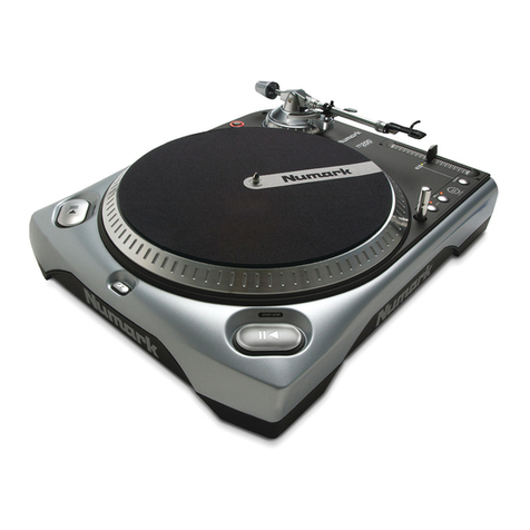
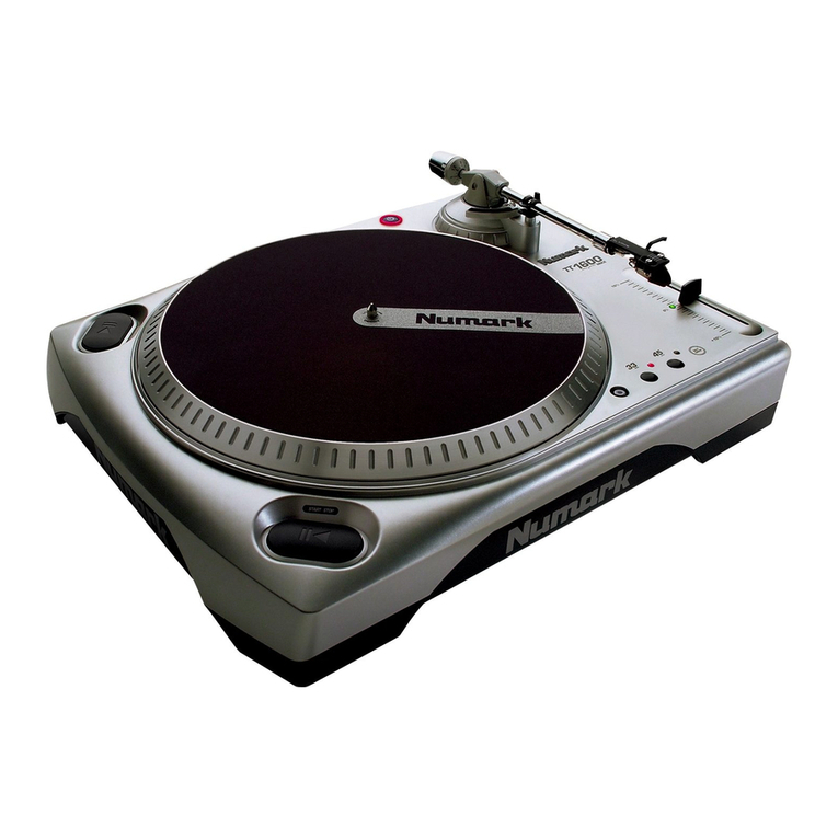
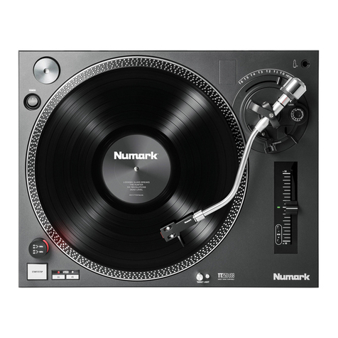
Numark TT1625 User manual

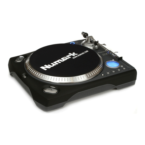
TT1625
PROFESSIONAL DJ TURNTABLE
Quickstart Guide (ENGLISH)
Guía de inicio rápido (ESPAÑOL)
Guide d’utilisation rapide (FRANÇAIS)
Guida rapida (ITALIANO)
Kurzanleitung (DEUTSCH)
SCHACHTELINHALT
-Plattenspieler
-Aluminium-Plattenteller mit Slipmat
-Vorgefertigtes Einbaumodul
-Gegengewicht
-45 RPM-Adapter
-Netzkabel
-RCA-Kabel
CONTENUTO DELLA CONFEZIONE
-Giradischi
-Piatto in Alluminio con slipmat
-Cartuccia Pre-Installata
-Contrappeso
-Adattatore 45 giri (RPM)
-Cavo di alimentazione IEC
-Cavo RCA
Contenu de la boîte
-Platine tourne-disque
-Plateau en aluminium avec tapis
-Cartouche prémontée
-Contrepoids
-Adaptateur 45 tour/minute (RPM)
-Câble d'alimentation CEI
-Câble RCA
CONTENIDOS DE LA CAJA:
-Giradiscos
-Plato de aluminio con alfombrilla
-Cartucho pre-montado
-Contrapeso
-Adaptador de 45 RPM
-Cable de alimentación IEC
-
CabledeRCA(stereo)
BOX CONTENTS
-Turntable
-Aluminum Platter with slipmat
-Pre-mounted cartridge
-Counterweight
-45 RPM adapter
-IEC power cable
-
S
t
e
r
eo
R
C
A
ca
bl
e

(ENGLISH) QUICKSTART GUIDE
1. Make sure all items listed on the front of this guide are included in the box.
2. READ SAFETY INSTRUCTION BOOKLET BEFORE USING THE PRODUCT
3. Go to http://www.numark.com for product registration.
GENERAL CONTROLS
1. Power Cable: This power cable should be plugged into a wall receptacle AFTER all audio connections are
made.
2. RCA Audio Output Cables: These cables are used to connect the turntable to a DJ mixer or amplifier that
has a built in PHONO PREAMP. This RCA type input is a feature that is commonly found on most DJ mixers
and will be labeled PHONO or TURNTABLE. If the RCA Audio Output Cables are not connected to a mixer or
amplifier with a PHONO PREAMP, then the audio output will be very quiet.
3. Ground Wire: This ground wire must be connected to a metal bolt or ground lug that is on the mixer or
amplifier that the turntable is connected to. If the ground wire is not securely fastened to a metal bolt or
ground lug, then the audio output will exhibit a “buzzing” sound.
4. Power Button: Turn on and turn off the machine with this button.
5. Platter: This aluminum platter must be securely fastened to the turntable prior to operation. See SETUP
INSTRUCTIONS for detailed information on installing the platter.
6. Start/Stop Buttons: These buttons start and stop the turntable motor. Both buttons have the same
function. If they seem to not be functioning, check to make sure that the platter is properly installed in the
SETUP INSTRUCTIONS.
7. 33 and 45 RPM Buttons: These buttons control the RPM of the turntable platter. A red LED indicates which
RPM mode has been selected.
NOTE: If the turntable is powered down while in the 45 RPM setting, it will return to 33 RPM when it is
powered up.
8. Pitch LED: This LED illuminates green when the pitch slider is set at 0%. When the pitch slider is moved
away from zero, the LED illuminates red.
9. Pitch Slider: This slide control allows the pitch to be increased or decreased by 10%. In the center position
the pitch is at 0%. When moved away from the center and towards the tone arm decreases the pitch (slows
down the platter) and moving the pitch slider away from the tone arm increase the pitch (speeds up the
platter.)
TONE ARM: Items 10 – 13 are all parts of the Tonearm. Refer to the TONEARM SETUP section for additional details on
these controls. Your model will be equipped with straight arm or S-arm style depending upon model purchased.
10. Counter Weight and Scale Ring: The Counterweight is used to balance the head shell and cartridge
assembly so that the proper amount of stylus pressure is applied to the record.
11. Anti-Skate Adjustment: This knob is used to compensate for inward tracking forces. See TONEARM SETUP
for more details.
12. Arm Clip: This specially designed arm clip secures the tone arm while at rest or when not in use. The arm
clip has been designed to remain in the up position while unlocked.
NOTE: When transporting the turntable, it is always recommended that the headshell be removed and the
arm clip secured to prevent tonearm or turntable damage.
13. Cartridge and Headshell: The cartridge is pre-mounted on a standard headshell. The cartridge is user
replaceable and compatible with a variety of standard cartridges. Be sure to remove the clear plastic cover
from the cartridge before operating the turntable.

PLATTER SETUP
WARNING: Incorrect Platter setup can lead to poor turntable performance, platter instability or permanent motor
damage.
1. Notice the locking pins shown. BE SURE THAT TURNTABLE IS NOT PLUGGED IN.
2. Match the inner motor to Figure 2.
3. Carefully place platter with holes aligned to base as shown.
4. Check to make sure the platter rotates uniformly.
TONEARM SETUP
1. Begin by rotating the counterweight clockwise until it is in the complete forward position (NOTE: this is also
the maximum amount of pressure that can be applied to the cartridge.)
2. Now there should be a feeling of weight and resistance when the head shell is raised and lowered. Begin
rotating the counterweight counter-clockwise (away from the pivot point) until the weight and resistance
feeling is gone. If done properly, the tone arm will pivot with very little resistance back and forth indicating
that there is exactly 0 grams of stylus pressure.
3. With the counterweight in its new position further away from tone arm pivot point, grasp the scale ring of
the counter weight and rotate it until "0" is in the vertical position.
4. Finally, rotate the counterweight (and scale ring) clockwise (towards the pivot point) until the desired
amount of weight is reached. If the scale rotates 360 degrees beyond the zero point, the new scale ring
reading should be added to 3.5.
*The included head shell and cartridge assembly requires a minimum of 3 grams and no more than 5 grams
for optimum performance.
Setting the Anti-Skate Adjustment
In most cases, the Anti-Skate should be set to its minimum setting. Anti-Skate compensates for inward
tracking forces that occur with certain cartridges when the stylus nears the center of the record. If the
turntable is experiencing excessive skipping during back-cueing and scratching while nearing the center
spindle, try increasing the Anti-Skate in the increments indicated on the dial. Start by adding an increment
of 1, test its performance, than increase it more, and so on.

(ESPAÑOL) GUÍA DE INICIO RÁPIDO
1. Asegúrese de que todos los artículos incluidos al inicio de este manual están incluidos en la caja.
2. LEA LAS INSTRUCCIONES DEL FOLLETO DE SEGURIDAD ANTES DE UTILIZAR EL PRODUCTO.
3. Visite http://www.numark.com para registrar el producto.
CONTROLES GENERALES
1. Cable de alimentación: Este cable de alimentación debe ser enchufado a una toma de corriente en la
pared DESPUÉS de que se realicen todas las conexiones de audio.
2. Cables RCA de salida de audio: Estos cables se utilizan para conectar el giradiscos a un mezclador de DJ
o a un amplificador que tiene un PHONO PREAMP instalado. Esta entrada tipo RCA es una característica que
se encuentra en la mayoría de los mezcladores de DJ y estará identificada con PHONO o TURNTABLE. Si los
cables de salida de audio RCA no son conectados a un mezclador o amplificador con PHONO PREAMP, la
salida de audio será muy baja.
3. Cable de conexión a tierra: Este cable de conexión a tierra debe ser conectado a una clavija metálica o a
una lengüeta de tierra del mezclador o amplificador al cual está conectado el giradiscos. Si el cable de
conexión a tierra no está bien ajustado a una clavija metálica o a una lengüeta de tierra, la salida de audio
tendrá un sonido de zumbido.
4. Botón de alimentación: Enciende y apaga la máquina con este botón.
5. Plato: Este plato de aluminio debe estar bien ajustado al giradiscos antes de hacerlo funcionar. Vea las
INSTRUCCIONES DE INSTALACIÓN para más información sobre la instalación del plato.
6. Botones Start/Stop: Estos botones ponen en marcha y detienen el motor del giradiscos. Ambos botones
tienen la misma función. Si parecen no funcionar, revise las INSTRUCCIONES DE INSTALACIÓN para
asegurarse de que el plato esté instalado correctamente.
7. Botones de 33 y 45 RPM (revoluciones por minuto): Estos botones controlan las RPM del plato del
giradiscos. Un LED rojo indica el modo de RPM que ha sido seleccionado.
NOTA: Si apaga el giradiscos mientras que está funcionando a 45 RPM, volverá a las 33 RPM cuando
encienda de nuevo el giradiscos.
8. LED del Pitch: Este LED se ilumina de color verde cuando el deslizador del pitch está fijado al 0%. Cuando
el deslizador del pitch es alejado del cero, el LED se ilumina de color rojo.
9. Deslizador del Pitch: Este deslizador permite aumentar o disminuir el pitch en un 10%. En la posición
central, el pitch está al 0%. Cuando es alejado del centro y se mueve hacia el brazo, esto disminuye el pitch
(baja la velocidad del plato) y cuando el deslizador del pitch es alejado del brazo, esto hace que aumente el
pitch (aumenta la velocidad del plato.)
EL BRAZO: Los artículos 10 – 13 forman todos parte del brazo. Consulte la sección INSTALACIÓN DEL BRAZO para más
detalles sobre estos controles. Su modelo estará equipado con un brazo recto o un brazo en forma de S, dependiendo del
modelo adquirido.
10. Contrapeso y anillo numerado: El contrapeso se usa para balancear el ensamblaje del portacápsulas y
del cartucho con el fin de aplicarle al disco la cantidad adecuada de presión de la aguja.
11. Ajuste Anti-Skate (anti-deslizamiento): Este botón se usa para compensar por las fuerzas de tracción
de entrada. Consulte la INSTALACIÓN DEL BRAZO para más detalles.
12. Clip del brazo: Este clip está diseñado especialmente para fijar el brazo mientras está en el soporte o
mientras no se usa. El clip ha sido diseñado para permanecer hacia arriba mientras no esté fijado.
NOTA: Al transportar el giradiscos, es siempre recomendable retirar el portacápsulas y sujetar con firmeza
el clip del brazo para evitar daños al brazo o al giradiscos.
13. Cápsula y portacápsula: La cápsula está preinstalada en un portacápsula estándar. La cápsula es
reemplazable por el usuario y compatible con una variedad de cápsulas estándar. Asegúrese de retirar la
cubierta plástica transparente antes de hacer funcionar el giradiscos con la cápsula.

INSTALACIÓN DEL PLATO
ADVERTENCIA: La instalación incorrecta del plato puede tener como consecuencia un mal rendimiento del
giradiscos, una inestabilidad del plato o un daño permanente al motor.
1. Observe los pasadores de bloqueo (locking pins) que se muestran. ASEGÚRESE QUE EL GIRADISCOS NO
ESTÉ ENCHUFADO.
2. Haga concordar el motor interior con la Figura 2.
3. Alinee los agujeros del plato cuidadosamente con la base, como se muestra aquí.
4. Compruebe que el plato gira de modo uniforme.
INSTALACIÓN DEL BRAZO
1. Comience por girar el contrapeso en el sentido de las agujas del reloj hasta que esté completamente en
posición hacia delante (NOTA: esta es también la máxima cantidad de presión que se le puede aplicar al
cartucho.)
2. Ahora debería haber una sensación de peso y resistencia al levantar o bajar el portacápsulas. Comience a
girar el contrapeso en el sentido contrario a las agujas del reloj (alejándolo del punto de giro) hasta que la
sensación de peso y resistencia desaparezca. Si esto se hace correctamente, el brazo girará de un lado al
otro con muy poca resistencia indicando que hay exactamente 0 gramos de presión sobre la aguja.
3. Con el contrapeso en su nueva posición, más alejado del punto de giro del brazo, tome el anillo numerado
del contrapeso y gírelo hasta que el “0” esté en la posición vertical.
4. Finalmente, gire el contrapeso (y el anillo numerado) en el sentido de las agujas del reloj (hacia el punto de
giro) hasta que alcance el peso deseado. Si el anillo numerado gira 360 grados más del punto cero, la nueva
cantidad del anillo numerado debería ser agregada a los 3.5.
*El ensamblaje del portacápsulas y del cartucho que se incluye aquí, requiere un mínimo de 3 gramos y un
máximo de 5 gramos para un rendimiento óptimo.
Ajuste del Anti-Skate (anti-deslizamiento)
En la mayoría de los casos, el Anti-Skate debería ser ajustado al mínimo. El anti-skate compensa por las
fuerzas de tracción de entrada que ocurren con ciertos cartuchos cuando la aguja se acerca al centro del
disco. Si el giradiscos experimenta excesivos saltos en los retrocesos rápidos y rayados cuando se acerca al
eje central, intente aumentar el Anti-Skate en los incrementos indicados en el botón. Comience agregando
un incremento de 1, pruebe su rendimiento y auméntelo más, y continúe así.

(FRANÇAIS) GUIDE D'UTILISATION RAPIDE
1. Vous assurer que tous les articles énumérés au début de ce guide sont inclus dans la boîte.
2. LIRE LE LIVRET D’INSTRUCTION DE SÉCURITÉ AVANT DE FAIRE USAGE DU PRODUIT.
3. Allez à http://www.numark.com pour enregistrer le produit.
COMMANDES GÉNÉRALES
1. Câble d’alimentation : Ce câble d’alimentation doit être branché à une prise murale UNIQUEMENT après
que tous les raccordements ont été effectués.
2. Câbles de sortie audio RCA : Ces câbles servent à brancher la platine tourne-disque à une console de
mixage ou à un amplificateur muni d’un préamplificateur phono. La plupart des consoles de mixage
professionnelle sont munies d’une entrée de type RCA étiquetée PHONO ou TURNTABLE. Si les câbles de
sortie audio RCA ne sont pas branchés à une console ou un amplificateur avec un préamplificateur phono la
sortie audio sera très discrète.
3. Fil de mise à terre : Le fil de mise à la terre doit être connecté à un boulon en métal ou à une cosse située
sur la console ou sur l’amplificateur auquel est branché la platine tourne-disque. Si le fil de mise à la terre
n’est pas bien raccordé à la borne métallique ou à la cosse, il peut y avoir un effet de bourdonnement à la
sortie audio.
4. Bouton d’alimentation : C’est le button qui permet d’allumer ou d’éteindre la machine.
5. Plateau : Le plateau en aluminium doit être solidement fixé à la platine tourne-disque avant l’utilisation.
Voir la section « Installation » pour plus de détails sur l’installation du plateau.
6. Interrupteurs Marche/Arrêt : Les interrupteurs servent à mettre le mécanisme d’entraînement du
plateau de la platine tourne-disque en marche ou à l’arrêt. Les deux interrupteurs ont la même fonction. Si
les interrupteurs ne fonctionnent pas bien, vérifiez si le plateau est correctement installé avec l’aide de la
section « Installation ».
7. Sélecteurs de vitesse 33 et 45 tr/min : Ces touches sélectionnent la vitesse du plateau de la platine
tourne-disque. Un voyant rouge indique quelle vitesse (tr/min) a été sélectionnée.
NOTE: Si la platine tourne-disque est mis hors tension en mode 45 tr/min, il reviendra automatiquement en
mode 33 tr/min lorsqu’il sera réactivé.
8. Voyant de la hauteur tonale : Ce voyant devient vert lorsque la commande de la hauteur tonale est
réglée à 0 %. Lorsque la commande de la hauteur tonale s’éloigne du 0, le voyant devient rouge.
9. Commande de la hauteur tonale : Cette commande permet d’augmenter ou de diminuer la hauteur
tonale de 10 %. En position centrale la hauteur tonale est à 0 %. Lorsque la commande est déplacée du
centre vers le bras de lecture, la hauteur tonale est diminuée (ralenti le plateau) et augmente à nouveau
lorsque la commande retourne vers le centre (accélère le plateau).
Bras de lecture : Les items 10 à 13 font partie du bras de lecture. Veuillez vous référez à la section « Réglage du bras
de lecture » pour plus de détails sur ces commandes. Votre modèle sera équipé d’un bras droit ou en S selon le modèle
acheté.
10. Contrepoids et anneaux de pression : Le contrepoids est utilisé pour équilibrer l'ensemble principal de la
coquille et de la cartouche de sorte que la pression de l'aiguille appliquée au disque soit adéquate.
11. Réglage de la commande anti-dérapage : Cette commande sert à compenser pour la force d’appui.
Veuillez vous référer à la section « Réglage du bras de lecture » pour plus de détails.
12. Serre-bras : Le serre-bras est conçu spécialement pour maintenir le bras de lecture en place lorsqu’il n’est
pas utilisé. Le serre-bras est conçu pour demeurer en position relevée lorsqu’il est déverrouillé.
NOTE : Lorsque la platine tourne-disque est déplacé, il est recommandé que la coquille soit enlevée et que
le serre-bras soit verrouillé pour éviter d’endommager le bras de lecture ou la platine tourne-disque.
13. Cartouche et coquille : La cartouche est préinstallée sur une coquille standard. La cartouche peut être
remplacée et est compatible avec les différentes cartouches standards. Assurez-vous de bien retirer le
plastique transparent avant de faire fonctionner le tourne-disque à partir de la cartouche.

Installation du plateau
Mise en garde : Une installation incorrecte du plateau peut occasionner un mauvais rendement de la platine
tourne-disque, une instabilité du plateau ou causer des dommages permanents au moteur.
1. Veuillez porter une attention particulière aux tiges de verrouillage (locking pins) illustrées ci dessus.
VEUILLEZ VOUS ASSURER QUE LE TOURNE DISQUE N’EST PAS BRANCHÉ À UNE PRISE ÉLECTRIQUE.
2. Alignez le moteur interne tel qu'indiqué à la figure 2.
3. Placez le plateau en alignant les trous à la base tel qu’indiqué.
4. Assurez-vous que le plateau tourne uniformément.
INSTALLATION DU BRAS DE LECTURE
1. Tournez le contrepoids dans le sens des aiguilles d’une montre jusqu’à ce qu’il soit complètement penché
vers l’avant (NOTE : C’est également la quantité de tension maximale qui peut être appliquée sur la
cartouche).
2. Il devrait y avoir maintenant un sentiment de tension et de résistance lorsque la coquille est levée et
abaissée. Tournez le contrepoids dans le sens inverse des aiguilles d’une montre (en vous éloignant du point
de pivot) jusqu’à ce que le sentiment de tension et de résistance soit parti. Lorsque fait correctement, le
bras de lecture devrait pivoter avec très peu de résistance indiquant qu’il y a 0 gramme de pression sur
l’aiguille.
3. Avec le contrepoids en sa nouvelle position éloignée du point de pivot du bras de lecture, saisissez l'anneau
de pression du contrepoids et tournez-le jusqu'à ce que « 0 » soit en position verticale.
4. Pour terminer, tournez le contrepoids (et l'anneau de pression) dans le sens des aiguilles d'une montre
(vers le point de pivot) jusqu'à ce que la quantité désirée de pression soit atteinte. Si le contrepoids tourne
360 degrés au-delà du point zéro, 3.5 devra être ajoutée à la nouvelle lecture de l'anneau de pression.
L'assemblage coquille et cartouche inclus avec la platine tourne-disque exige un minimum de 3 grammes et
un maximum de 5 grammes pour un rendement optimal.
Réglage de la commande anti-dérapage
Dans la plupart des cas, la commande anti-dérapage doit être réglée au minimum. L’anti-dérapage
compense pour la force d’appui qui se produit avec certaines cartouches lorsque l'aiguille s'approche du
centre du disque. Si la platine tourne-disque saute excessivement pendant la lecture inversée et le scratch
tout en s'approchant de l'axe central, essayez d’augmenter l'anti-dérapage en utilisant les incréments
indiqués sur le cadran. Commencez par ajouter un incrément de 1, examinez le résultat, ensuite
augmentez-le un peu plus, et ainsi de suite.

(ITALIANO) GUIDA RAPIDA
1. Verificate che tutti gli elementi elencati sul frontespizio di questo manuale siano inclusi nella confezione.
2. PRIMA DI UTILIZZARE IL PRODOTTO LEGGETE IL LIBRETTO DELLE ISTRUZIONI DI SICUREZZA.
3. Andate sul sito http://www.numark.com per la registrazione del prodotto.
COMANDI GENERALI
1. Cavo di Alimentazione: Il cavo di alimentazione va inserito in una presa a muro DOPO aver effettuato i
collegamenti audio.
2. Cavi di Uscita Audio RCA: Questi cavi vengono impiegati per collegare il giradischi ad un DJ mixer o ad un
amplificatore che presentino un PHONO PREAMP incorporato. Questo ingresso di tipo RCA è una
caratteristica che si trova comunemente nella maggior parte dei DJ mixer, e viene indicato come PHONO o
TURNTABLE. Se i Cavi di Uscita Audio RCA non sono collegati ad un mixer o ad un amplificatore dotato di
PHONO PREAMP, l’uscita audio sarà molto silenziosa.
3. Capocorda di Terra: Il capocorda di terra deve essere collegato ad un bullone metallico o ad un filo di terra
situato sul mixer o sull’amplificatore a cui è collegato il giradischi. Se il capocorda di terra non viene fissato
saldamente ad un bullone metallico o ad un filo di terra, l’uscita audio emetterà un suono “ronzante”.
4. Tasto di Accensione: Questo è il pulsante che permette di accendere e di spegnere l’apparecchio.
5. Piatto: Questo piatto in alluminio dev’essere fissato saldamente al giradischi prima della messa in funzione.
Per istruzioni dettagliate sull’installazione del piatto, vedi ISTRUZIONI D’IMPOSTAZIONE.
6. Tasti Start/Stop: Questi tasti avviano e arrestano il motore del giradischi. Entrambi i tasti hanno la stessa
funzione. Se questo non sembra funzionare, consultare le ISTRUZIONI D’IMPOSTAZIONE per assicurarsi che
il piatto sia installato correttamente.
7. Tasti 33 e 45 giri (RPM): Questi tasti regolano il numero di giri al minuto (RPM) del piatto del giradischi.
Un LED rosso indica la modalità di giri RPM selezionata.
ATTENZIONE: Se il giradischi viene spento con impostazione a 45 giri, al momento dell’accensione tornerà
a 33 giri.
8. LED del Pitch : Questo LED si illumina di verde quando il cursore del pitch viene impostato allo 0%.
Quando il cursore del pitch viene allontanato dallo zero, il LED si illumina di rosso.
9. Cursore del Pitch: Questo comando a cursore consente un aumento o una diminuzione del pitch del 10%.
In posizione centrale il pitch è impostato allo 0%. Quando viene allontanato dal centro e mosso verso il
braccio dimunuisce il pitch (rallenta il piatto), mentre il movimento del cursore lontano dal braccio aumenta
il pitch (accelera il piatto).
BRACCIO: Gli accessori 10 – 13 sono tutti componenti del Braccio. Per ulteriori dettagli su questi comandi fare
riferimento al paragrafo IMPOSTAZIONE DEL BRACCIO. A seconda del modello acquistato, l’apparecchio sarà
equipaggiato con un braccio dritto oppure a S.
10. Contrappeso e Anello Graduato: Il Contrappeso viene utilizzato per equilibrare il fonorivelatore e la
cartuccia in modo tale che venga applicata la giusta pressione della puntina sul disco.
11. Dispositivo Anti-Skating: Questa manopola viene impiegata per compensare la forza centrifuga di
rotazione del disco. Per maggiori dettagli vedi IMPOSTAZIONE DEL BRACCIO.
12. Fermabraccio: Questo fermabraccio dal design specifico, mantiene il braccio fissato quando è a riposo o
non in uso. Il fermabraccio è stato progettato in modo tale da rimanere sollevato quando è sganciato.
ATTENZIONE: Durante il trasporto del giradischi, è sempre raccomandato di rimuovere il fonorivelatore e di
fissare il fermabraccio per evitare danni al braccio o al giradischi.
13. Cartuccia e fonorivelatore: La cartuccia è pre-installata su un fonorivelatore standard. La cartuccia è
sostituibile dall’utente e compatibile con numerose cartucce standard. Assicurarsi di rimuovere la copertura
in plastica trasparente prima di utilizzare il giradischi dalla cartuccia.

IMPOSTAZIONE DEL PIATTO
AVVERTENZA: Un’impostazione scorretta del Piatto può provocare prestazioni scadenti del giradischi, instabilità
del piatto o danni permanenti al motore.
1. Notare i perni di bloccaggio (locking pins) illustrati. ASSICURARSI CHE IL GIRADISCHI NON SIA
COLLEGATO.
2. Abbinare il motore interno alla Figura 2.
3. Posizionare il piatto badando di allineare i fori alla base come illustrato.
4. Verificare che il piatto ruoti uniformemente.
IMPOSTAZIONE DEL BRACCIO
1. Iniziare ruotando il contrappeso in senso orario fino a raggiungere la posizione a termine completa
(ATTENZIONE: questo è anche l’ammontare massimo di pressione che può essere applicato alla cartuccia.)
2. Ora, quando il fonorivelatore viene sollevato e abbassato, ci deve essere una sensazione di peso e di
resistenza. Iniziare ruotando il contrappeso in senso antiorario (lontano dal punto di perno) fino a quando la
sensazione di peso e di resistenza non sarà scomparsa. Se l’operazione viene svolta correttamente, il
braccio pivotterà in avanti e indietro con una resistenza minima, ad indicare che la puntina esercita una
pressione di 0 grammi esatti.
3. Quando il contrappeso si trova nella sua nuova posizione ulteriormente lontana dal punto di perno del
braccio, afferrare l’anello graduato del contrappeso e farlo ruotare fino a quando lo "0" viene a trovarsi in
posizione verticale.
4. Infine, ruotare il contrappeso (e l’anello graduato) in senso orario (verso il punto di perno) fino a
raggiungere la quantità di peso desiderata. Se viene ruotato di 360 gradi oltre il punto di zero, la nuova
lettura dell’anello graduato va aggiunta a 3.5.
*Per garantire prestazioni ottimali, il fonorilevatore e la cartuccia richiedono un peso minimo di 3 grammi e
fino ad un massimo di 5 grammi.
Impostazione del Dispositivo Anti-Skating
Nella maggior parte dei casi, l’Anti-Skating deve essere impostato al minimo. Questo dispositivo compensa
le forze centrifughe che si verificano con alcune cartucce quando la puntina si avvicina al centro del disco.
Se il giradischi subisce un eccessivo skipping durante il back-cue e lo scratch al momento dell’avvicinamento
all’asse centrale, provare ad aumentare l’Anti-Skating degli incrementi indicati sul quadrante. Iniziare con un
incremento di 1, testare la resa, quindi aumentare ulteriormente, e così via.

(DEUTSCH) KURZANLEITUNG
1. Versichern Sie sich, daß alle im Anfang dieser Anleitung aufgeführten Teile in der Schachtel enthalten sind.
2. LESEN SIE DIE SICHERHEITSBROSCHÜRE BEVOR SIE DAS GERÄT BENUTZEN
3. Um das Produkt zu registrieren, besuchen Sie bitte http://www.numark.com.
ALLGEMEINE BEDIENELEMENTE
1. Stromkabel: Das Stromkabel wird in eine Steckdose gesteckt, NACHDEM alle Tonanschlüsse erfolgt sind.
2. RCA-Tonausgabekabel: Diese Kabel dienen zum Anschluß des Plattenspielers an ein DJ-Mischpult oder
einen Verstärker, welche einen eingebauten PHONO-VORVERSTÄRKER besitzen. Diese Art von RCA-Eingang
kommt bei den meisten DJ-Mischpults vor und ist mit PHONO oder PLATTENSPIELER gekennzeichnet. Falls
die RCA-Tonausgabekabel nicht an ein Mischpult oder Vorverstärker mit PHONO-VORVERSTÄRKER
angeschlossen werden, ist die Tonausgabe sehr leise.
3. Erdungskabel: Dieses Erdungskabel muß an eine am Mischpult oder Verstärker befindliche Metallschraube
oder einem Erdungsanschluß angeschlossen werden. Falls das Erdungskabel nicht fest mit der
Metallschraube oder dem Erdungsanschluß verbunden ist, wird die Tonausgabe ein Summgeräusch
aufweisen.
4. Ein/Ausschaltknopf: Schalten Sie das Gerät mit dieser Taste ein oder aus.
5. Plattenteller: Dieser Aluminium-Plattenteller muß vor Inbetriebnahme mit dem Plattenspieler fest
verbunden sein. Für Einzelheiten zur Installation der Plattenteller lesen Sie bitte die AUFBAUANLEITUNG.
6. Start/Stop-Tasten: Diese Tasten setzen den Plattenteller in Bewegung und halten ihn an. Beide Tasten
haben dieselbe Funktion. Falls diese nicht zu funktionieren scheinen, überprüfen Sie in der Aufbauanleitung,
daß der Plattenteller korrekt installiert ist.
7. 33 und 45 RPM-Tasten: Diese Tasten steuern die Umdrehungsgeschwindigkeit des Plattentellers. Eine rote
Leuchtdiode gibt an, welche Umdrehungsgeschwindigkeit gewählt wurde.
NOTE: Falls der Plattenspieler bei einer Einstellung von 45 RPM ausgeschaltet wurde, geht diese
automatisch auf 33 RPM zurück, wenn wieder eingeschaltet wird.
8. Tonhöhe-Leuchtdiode: Diese Leuchtdiode leuchtet grün auf, wenn der Tonhöhenregler auf 0% steht.
Wenn der Tonhöhenregler von 0 wegbewegt wird, leuchtet die Anzeige in rot auf.
9. Tonhöhenregler: Mit diesem Schieberegler läßt sich die Tonhöhe um 10% erhöhen oder vermindern. In
der mittleren Stellung ist die Tonhöhe bei 0%. Wenn der Regler von der Mitte in Richtung Tonarm bewegt
wird, vermindert sich die Tonhöhe (Plattenteller wird langsamer), wenn vom Tonarm weg bewegt wird,
erhöht sich die Tonhöhe (Plattenteller wird schneller.)
TONARM: Die Teile 10 – 13 sind alle Teile des Tonarms. Für zusätzliche Einzelheiten über diese lesen Sie bitte im
Abschnitt TONARM-AUFBAU nach. Abhängig vom gekauften Modell ist Ihres entweder mit einem geraden oder S-förmigen
Arm ausgerüstet.
10. Gegengewicht und Skalenring: Das Gegengewicht dient dazu, den Tonkopf mit Einsteckmodul so
auszubalancieren, daß der korrekte Tonnadeldruck auf die Schallplatte ausgeübt wird.
11. Anti-Skate-Einstellung: Dieser Drehknopf dient zum Ausgleich von nach innen gerichteten Kräften. Für
weitere Einzelheiten, lesen Sie bitte im Abschnitt TONARM-AUFBAU nach.
12. Arm-Clip: Dieser speziell entworfene Arm-Clip sichert den Tonarm während Pausen und bei Nichtgebrauch.
Der Arm-Clip wurde so entworfen, daß er in der aufrechten Stellung verbleibt wenn unverschlossen.
HINWEIS: Beim Transport des Plattenspielers ist es immer empfehlenswert, das Tonkopfgehäuse zu
entfernen und den Arm-Clip zu verschliessen, um den Tonarm oder den Plattenspieler vor Beschädigung zu
schützen.
13. Tonabnehmersystem und Headshell: Das Tonabnehmersystem ist auf eine Standard-Headshell
vormontiert. Sowohl das Tonabnehmersystem als auch die Nadel kann selbst ausgetauscht werden und ist
kompatibel mit den meisten Standard DJ Systemen. Vor dem ersten Gebrauch entfernen Sie die Plastik
Schutzkappe vom System.
AUFBAU DES PLATTENTELLERS
WARNUNG: Unvorschriftsmäßiger Aufbau des Plattentellers kann zu schlechter Leistung des Plattenspielers,
Instabilität des Tellers oder zu permanentem Schaden des Motors führen.
1. Sehen Sie sich die gezeigten Sicherungsstifte (Locking Pins) an. STELLEN SIE SICHER, DASS DER
PLATTENSPIELER NICHT ANS NETZ ANGESCHLOSSEN IST.
2. Drehen Sie den inneren Motor in die auf Abbildung 2 gezeigte Stellung.
3. Legen Sie den Plattenteller vorsichtig wie gezeigt auf, sodass sich die Löcher mit denen der Basis in einer
Linie befinden.
4. Stellen Sie sicher, daß der Plattenteller rund läuft.
AUFBAU DES TONARMS
1. Zuerst drehen Sie das Gegengewicht im Uhrzeigersinn, bis es sich vollständig in der vordersten Position
befindet (HINWEIS: dies ist zugleich der größtmögliche Druck, der auf das Einsteckmodul ausgeübt werden
darf.)
2. Sie sollten nun Gewicht und Widerstand fühlen können, wenn das Kopfgehäuse angehoben und abgesenkt
wird. Fangen Sie nun an, das Gegengewicht gegen den Uhrzeigersinn (weg vom Schwenkpunkt) so lange zu
drehen, bis das Gefühl von Gewicht und Widerstand nicht mehr wahrzunehmen sind. Falls dies genau
ausgeführt wird, schwenkt der Tonarm ohne großen Widerstand auf und ab, was bedeutet, daß der Druck
auf der Abtastnadel genau 0 Gramm beträgt.
3. Mit dem Gegengewicht in der neuen, vom Schwenkpunkt des Tonarms weiter entfernten Position, drehen
Sie den Skalenring des Gegengewichts solange, bis “0” in der vertikalen Position steht.
4. Zuletzt drehen Sie das Gegengewicht (und den Skalenring) im Uhrzeigersinn (zum Schwenkpunkt hin) bis
das gewünschte Gewicht erreicht ist. Falls die Skala sich mehr als 360 Grad über den Nullpunkt hinaus
dreht, sollte der angezeigte neue Wert des Skalenrings zu 3.5 dazuaddiert werden.
*Das mitgelieferte Kopfgehäuse und Einsteckmodul erfordern mindestens 3, jedoch höchstens 5 Gramm für
optimale Leistung.
Einstellung des Anti-Skate
In den meisten Fällen sollte das Anti-Skate auf seinen minimalsten Wert eingestellt werden. Anti-Skate gleicht nach
innen gerichtete Kräfte aus, welche bei manchen Einsteckmodulen auftreten, wenn sich die Abtastnadel auf die
Plattenmitte zubewegt. Falls beim Plattenspieler während Back-Cueing und Scratching beim Zubewegen auf die
Zentralspindel außergewöhnlich starkes “Skipping” auftritt, versuchen Sie das Anti-Skate in den auf der Anzeige
gezeigten Schritten zu erhöhen. Fangen Sie mit einer Steigerung von 1 an, testen Sie das Verhalten, dann steigern Sie es
weiter, und so fort.

Table of contents
Languages:
Other Numark Turntable manuals

Numark
Numark TT1600 Technical document

Numark
Numark NTX1000 User manual

Numark
Numark NTX1000 User manual

Numark
Numark TT1700 User manual

Numark
Numark PT-01 Technical document

Numark
Numark NS7 User manual

Numark
Numark TTUSB User manual

Numark
Numark PRO TT-1 User manual

Numark
Numark TT500 User manual

Numark
Numark X2 Technical document

Numark
Numark TTX1 User manual

Numark
Numark TT200 User manual

Numark
Numark PRO TT-2 User manual

Numark
Numark PT01USB Technical document

Numark
Numark TT-1520 User manual

Numark
Numark V7 User manual

Numark
Numark TTX1 User manual

Numark
Numark TT-100 User manual

Numark
Numark II2200 User manual

Numark
Numark PT-01 User manual