manuals.online logo
Brands
  1. Home
  2. •
  3. Brands
  4. •
  5. Nuova Marea
  6. •
  7. Cables And Connectors
  8. •
  9. Nuova Marea NM-251A-MUX User manual

Nuova Marea NM-251A-MUX User manual

nuova marea ltd
marine electronics & design
Address: 26 Mirtidiotissis str, Kastella, 18533 Piraeus, Greece
Tel.: +30.210.4134628, +30.210.4134698, Fax: +30.210.4134814
website: www.nuovamarea.com e-mail: sales@nuovamarea.com
Page | 1
NM-251A-MUX
Dual Input NMEA Buffer Splitter With Multiplex Functions
User Guide
V1.01
Introduction
NM-251A-MUX is a two input channel
multiplexer with five output channels NMEA-0183
data multiplier. It enables combining and multiplying
of NM-0183 sources to all navigational instruments
through five talker ports and PC connection through
RS-232.
Operation
NM-251A-MUX acquires the NM-0183 signals
from the two optically isolated inputs, combines the
data and outputs them to the five general output
ports and the RS-232 output. The NM-251A-MUX has
three distinct functional modes that can be selected
from the user via dip-switches:
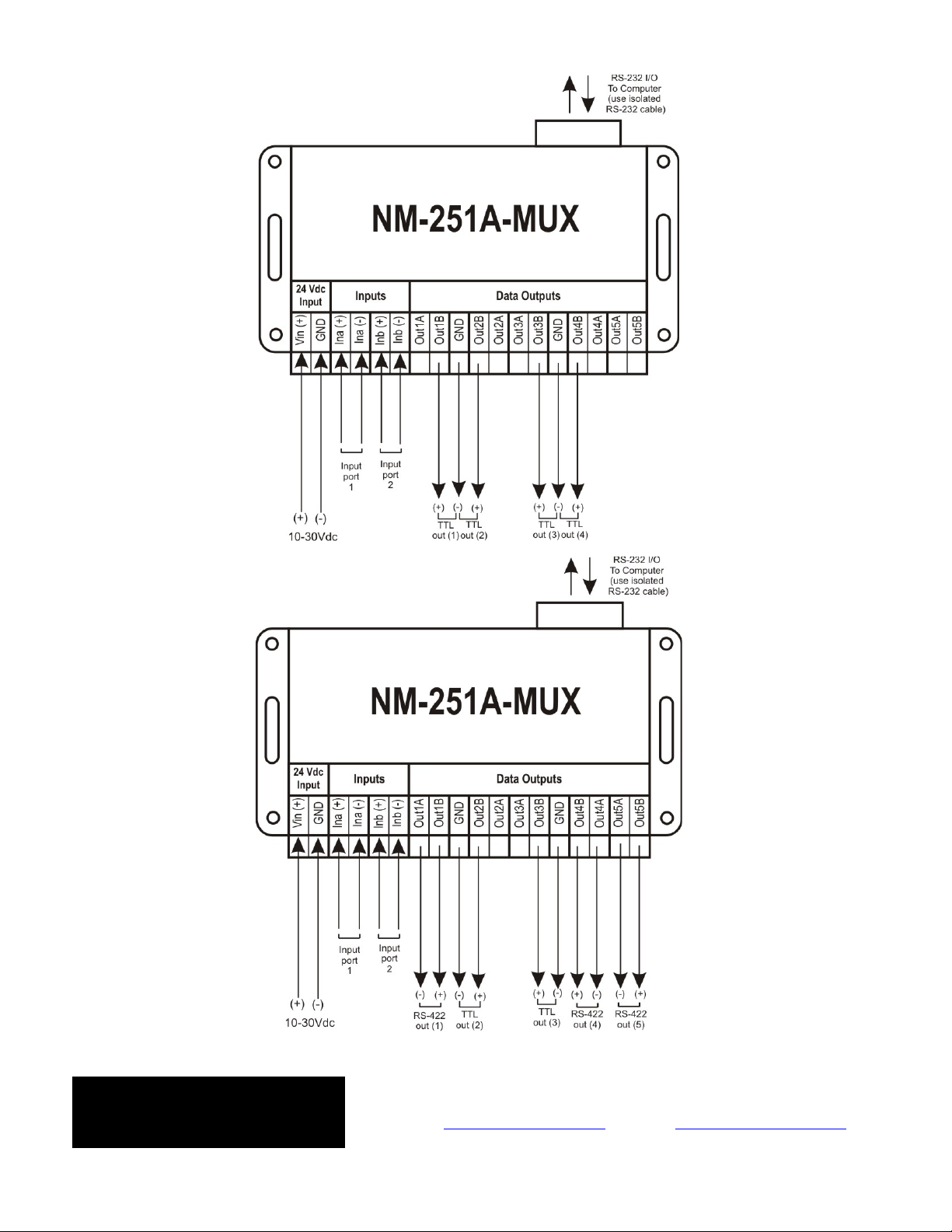
1. Mux mode: The combined output is routed to all five output ports and the RS-232 output. All
outputs can be configured to transmit at 4.800/9.600/19.200 or 38.400 baud.
2. Split/Mux mode: The combined output is routed to the fifth output and the RS-232 interface while
the first input is transmitted to outputs 1&2 and the second input to outputs 3&4. Combined output
only can be configured to transmit at 4.800/9.600/19.200 or 38.400 baud.
3. Fallback mode: NM-251A-MUX acquires NMEA-0183 sentences from the most significant input and
immediately sends them to the general purpose outputs and the RS-232 output. A watchdog timer
routine supervises if the NMEA signals are correctly applied in the primary input and switches to the
secondary input whenever there is no NMEA sentence for at least eight seconds. In this case the
secondary input starts receiving data if there is an instrument attached. If not, the device
automatically returns to the primary input after eight seconds. When the secondary input is already
in receiving mode and an NMEA signal is applied to the primary port, the device immediately
switches to the primary input. In the case that no signal is applied to any input, the device “circles”
around sampling the two listener ports every eight seconds until an NMEA-0183 signal appears to
any of the two listener ports.
The NM-251A-MUX has also the following features:
1. Configurable output transmission speed: The output speed for the combined data stream is
user selectable via dip-switches and can be set to 4.800/9.600/19.200 or 38.400 baud.
2. Input Autosense: The NM-251A-MUX senses a correct NMEA signal application to any of the two
inputs while in mux or split/mux mode. The LED Ina and Inb flash at 1/2 Hz while no NMEA signal is
applied or the polarity is wrong. If at least one signal is correctly connected to one of the inputs it
starts functioning normally.
3. Data overflow indications: The NM-251A-MUX has different overflow indication for each input.
When an overflow occurs some of the input data are not transmitted. This is normal when
connecting to instruments transmitting great amount of data, and can be resolved if the output
transmission speed is increased.
4. Watchdog: The integrated watchdog reset feature will bring NM-251A-MUX back from any
unresponsive state into normal operation.
nuova marea ltd
marine electronics & design
Address: 26 Mirtidiotissis str, Kastella, 18533 Piraeus, Greece
Tel.: +30.210.4134628, +30.210.4134698, Fax: +30.210.4134814
website: www.nuovamarea.com e-mail: sales@nuovamarea.com
Page | 2
Input Ports (listeners)
The NM-251A-MUX has two input ports that can be connected to any instrument intended for marine use
that can output NMEA-0183 signals. Each one of the two listener ports is optoisolated as specified in NMEA-0183
protocol, thus data(-) pole should never be connected to NM-251A-MUX ground. If the instrument’s talker port
is single ended, connect that terminal to the Ina(+) or Inb(+) input and tide the Ina(-) or Inb(-) to instrument’s
ground. If an RS-232 signal level is connected the ground pole (GND) should be connected to Ina(+) or Inb(+)
and the data pole (TXD) to Ina(-) or Inb(-) respectively.
The two listener ports can acquire NMEA sentences carried in TTL, RS-232 and RS-485/422 signal levels.
Output Ports (Talkers)
Each of the five general purpose talker ports transmit NMEA sentences in both RS422 and TTL signal
levels, depending on the connection topology chosen (see figure 1, 2 and 3), and can fan out one instrument.
Current drawn from each port is efficient enough to drive any NMEA compatible instrument.
The RS-232 port can deliver NMEA sentences to any modern computer running the appropriate software
on Windows 98 and above provided that serial communication follows the 4.800, 9.600, 19.200 or 38.400/8/N/1
standard. This port is not optically isolated and should be used for testing purposes only to avoid current
leakage. It can be used though to interface a computer system if proper isolation is achieved or if the computer
is supplied from an isolated power supply.
The NM-251A-MUX can be connected as shown in figures 1,2 and 3 using all RS-422 outputs (figure 1),
all TTL outputs (figure 2) or using either the RS-422 or TTL output of each port taking care not to connect the
same port for both signal level outputting.
Figure 1: Connection to RS-422 Outputs
nuova marea ltd
marine electronics & design
Address: 26 Mirtidiotissis str, Kastella, 18533 Piraeus, Greece
Tel.: +30.210.4134628, +30.210.4134698, Fax: +30.210.4134814
website: www.nuovamarea.com e-mail: sales@nuovamarea.com
Page | 3
Figure 2: Connection to TTL outputs
Figure 3: Combined use of TTL and RS-422 outputs
nuova marea ltd
marine electronics & design
Address: 26 Mirtidiotissis str, Kastella, 18533 Piraeus, Greece
Tel.: +30.210.4134628, +30.210.4134698, Fax: +30.210.4134814
website: www.nuovamarea.com e-mail: sales@nuovamarea.com
Page | 4
Power Supply
The NM-251A-MUX can be powered within the range of 10-35 VDC. The nominal voltage of 24 Vdc is
advised for powering the device in normal operation.
Power input port has a protection for incorrect polarity connection of the supplying voltage.
LED Indicator sequence
Ina LED
Flashing at 1/2 Hz: no input or incorrect polarity
Flashing randomly: Data overflow at input port 1
Inb LED
Flashing at 1/2 Hz: no input or incorrect polarity
Flashing randomly: Data overflow at input port 1
Out 3/4 LED
Flashing indicates data transmission to output port 3 and 4
Out 1/2 LED
Flashing indicates data transmission to output port 1 and 2
Out5 LED
Flashing indicates transmission to Out5 port and the RS-232 interface
Printed Circuit Board composite layout
Figure 4: Composite layout of NM-251A-MUX printed circuit board
nuova marea ltd
marine electronics & design
Address: 26 Mirtidiotissis str, Kastella, 18533 Piraeus, Greece
Tel.: +30.210.4134628, +30.210.4134698, Fax: +30.210.4134814
website: www.nuovamarea.com e-mail: sales@nuovamarea.com
Page | 5
Dip Switch Settings
Note: To achieve any of the following configurations a power cycle should be performed after setting the dip-
switched on the NM-251A-MUX
Configuration Input – Output routing Functionality Description
SW-1
SW-2
SW-3
SW-4
J5
J6
Out
1/2
Out
3/4
RS
232
Out
5
OFF OFF OFF OFF 1-2
1-3
MUX MODE
Combined data at 4.800/8/N/1
Combined data are transmitted to
all outputs at 4.800/8/N/1
OFF
ON OFF 1-2
1-3
MUX MODE
Combined data at 9.600/8/N/1
Combined data are transmitted to
all outputs at 9.600/8/N/1
OFF OFF OFF ON 1-2
1-3
MUX MODE
Combined data at 19.200/8/N/1
Combined data are transmitted to
all outputs at 19.200/8/N/1
OFF OFF ON ON 1-2
1-3
MUX MODE
Combined data at 38.400/8/N/1
Combined data are transmitted to
all outputs at 38.400/8/N/1
ON OFF OFF OFF 1-2
1-3
SPLIT/MUX MODE
Out1/2 same as INA (4.800/8/N/1)
Out3/4 same as INB (4.800/8/N/1)
Out5 and RS-232 combined data at
4.800/8/N/1
INA INB Combined data
At 4.800/8/N/1
ON OFF ON OFF 1-2
1-3
SPLIT/MUX MODE
Out1/2 same as INA (4.800/8/N/1)
Out3/4 same as INB (4.800/8/N/1)
Out5 and RS-232 combined data at
9.600/8/N/1
INA INB Combined data
at 9.600/8/N/1
ON OFF OFF ON 1-2
1-3
SPLIT/MUX MODE
Out1/2 same as INA (4.800/8/N/1)
Out3/4 same as INB (4.800/8/N/1)
Out5 and RS-232 combined data at
19.200/8/N/1
INA INB Combined data
at 19.200/8/N/1
ON OFF ON ON 1-2
1-3
SPLIT/MUX MODE
Out1/2 same as INA (4.800/8/N/1)
Out3/4 same as INB (4.800/8/N/1)
Out5 and RS-232 combined data at
38.400/8/N/1
INA INB Combined data
at 38.400/8/N/1
OFF ON OFF OFF 1-2
1-3
FALLBACK MODE
INA OR INB at 4.800/8/N/1
All outputs connected to INA or INB
if no signal applied to INA. Reception
and transmission at 4.800/8/N/1
OFF ON ON OFF 1-2
1-3
FALLBACK MODE
INA OR INB at 9.600/8/N/1
All outputs connected to INA or INB
if no signal applied to INA. Reception
and transmission at 9.600/8/N/1
OFF ON OFF ON 1-2
1-3
FALLBACK MODE
INA OR INB at 19.200/8/N/1
All outputs connected to INA or INB
if no signal applied to INA. Reception
and transmission at 19.200/8/N/1
OFF ON ON ON 1-2
1-3
FALLBACK MODE
INA OR INB 38.400/8/N/1
All outputs connected to INA or INB
if no signal applied to INA. Reception
and transmission at 38.400/8/N/1
X X ON ON X X NOT APPLICABLE
Table 1: NM-251A-MUX Configuration
nuova marea ltd
marine electronics & design
Address: 26 Mirtidiotissis str, Kastella, 18533 Piraeus, Greece
Tel.: +30.210.4134628, +30.210.4134698, Fax: +30.210.4134814
website: www.nuovamarea.com e-mail: sales@nuovamarea.com
Page | 6
Specifications
Supply Voltage
9 to 35 Vdc
Power Supply Protection
PTC Resettable Fuse
Vmax: 60V, Imax: 40A, Ihold: 0,25A (23°C),
Itrip:0,5A (23°C), Max time to trip (23°C): 2,2sec for 1,25A
Current Consumption
50mA in idle state/ 150mA in full output mode
Inputs
2 x NMEA-0183, optically isolated
Common Mode Rejection: 10kV/usec, Isolation: 480 Vrms
Input Resistance
1,5 KOhm
Outputs
5 x buffered RS-422/TTL (general purpose)
1 x RS-232
Output protection
Buffered for all RS-422 outputs
Speed for NMEA inputs
4.800/8/N/1 in mux and split/mux mode
4.800, 9.600, 19.200 or 38.400/8/N/1 when configured in fallback mode
Speed for NMEA outputs
4.800, 9.600, 19.200 or 38.400/8/N/1 user selectable
Indicators
Ina LED: Data overflow at input port 1 or no signal or incorrect polarity
Inb LED: Data overflow at input port 2 or no signal or incorrect polarity
Out 1/2 LED : Data transmission from output ports 1 and 2
Out 3/4 LED Data transmission from output ports 3 and 4
Out 5 LED: Data transmission from output ports 5 and RS-232 interface
Dimensions
Width = 110mm/134,80 mm
Depth = 82 mm
Height = 43 mm
Housing
Styrene
nuova marea ltd
marine electronics & design
Address: 26 Mirtidiotissis str, Kastella, 18533 Piraeus, Greece
Tel.: +30.210.4134628, +30.210.4134698, Fax: +30.210.4134814
website: www.nuovamarea.com e-mail: sales@nuovamarea.com
Page | 7
Port ID Wire ID / Color Cable ID Signal Description
Vin(+)
GND
Ina(+)
Ina(-)
Inb(+)
Inb(-)
Out1A
Out1B
GND
Out2B
Out2A
Out3A
Out3B
GND
Out4B
Out4A
Out5A
Out5B
SETTINGS
J5*
J6*
Dip Switches**
2
1
3
2
1
3
ID
OFF
ON
1
* Mark the positions that are occupied by the jumper
** Mark the position for every switch
2
3
4
NOTES:
nuova marea ltd
marine electronics & design
Address: 26 Mirtidiotissis str, Kastella, 18533 Piraeus, Greece
Tel.: +30.210.4134628, +30.210.4134698, Fax: +30.210.4134814
website: www.nuovamarea.com e-mail: sales@nuovamarea.com
Page | 8

Popular Cables And Connectors manuals by other brands

nvent RAYCHEM C25-100-METAL-FHP manual

nvent

nvent RAYCHEM C25-100-METAL-FHP manual

Tyco Electronics CPC 45 Series instruction sheet

Tyco Electronics

Tyco Electronics CPC 45 Series instruction sheet

Banner Plastic Fiber Optic PBT46UC installation instructions

Banner

Banner Plastic Fiber Optic PBT46UC installation instructions

iSimple MediaWire PRO IS76PRO owner's manual

iSimple

iSimple MediaWire PRO IS76PRO owner's manual

American TIM-3900 Series manual

American

American TIM-3900 Series manual

KRAM telecom 68678 instructions

KRAM telecom

KRAM telecom 68678 instructions

Beta 1843BM Instructions for use

Beta

Beta 1843BM Instructions for use

Tektronix KEITHLEY 4200-MTRX-X manual

Tektronix

Tektronix KEITHLEY 4200-MTRX-X manual

Fluke USB-IR installation guide

Fluke

Fluke USB-IR installation guide

KHONS EVSE 8-16A instructions

KHONS

KHONS EVSE 8-16A instructions

J-Tech Digital JTDSP0103 Setup

J-Tech Digital

J-Tech Digital JTDSP0103 Setup

Kenwood KPG-22U Troubleshooting

Kenwood

Kenwood KPG-22U Troubleshooting

Chauvet Professional Net-X II user manual

Chauvet Professional

Chauvet Professional Net-X II user manual

ADC DS1 VDSL-Grade Transport System Cable... Specification sheet

ADC

ADC DS1 VDSL-Grade Transport System Cable... Specification sheet

RS 406-004 Instruction leaflet

RS

RS 406-004 Instruction leaflet

Cablexpert DSP-8PH4-02 user manual

Cablexpert

Cablexpert DSP-8PH4-02 user manual

Pentair Raychem E-100-A installation instructions

Pentair

Pentair Raychem E-100-A installation instructions

Volkswagen VAS 6558A/28 operating manual

Volkswagen

Volkswagen VAS 6558A/28 operating manual

manuals.online logo
manuals.online logoBrands
  • About & Mission
  • Contact us
  • Privacy Policy
  • Terms and Conditions

Copyright 2025 Manuals.Online. All Rights Reserved.