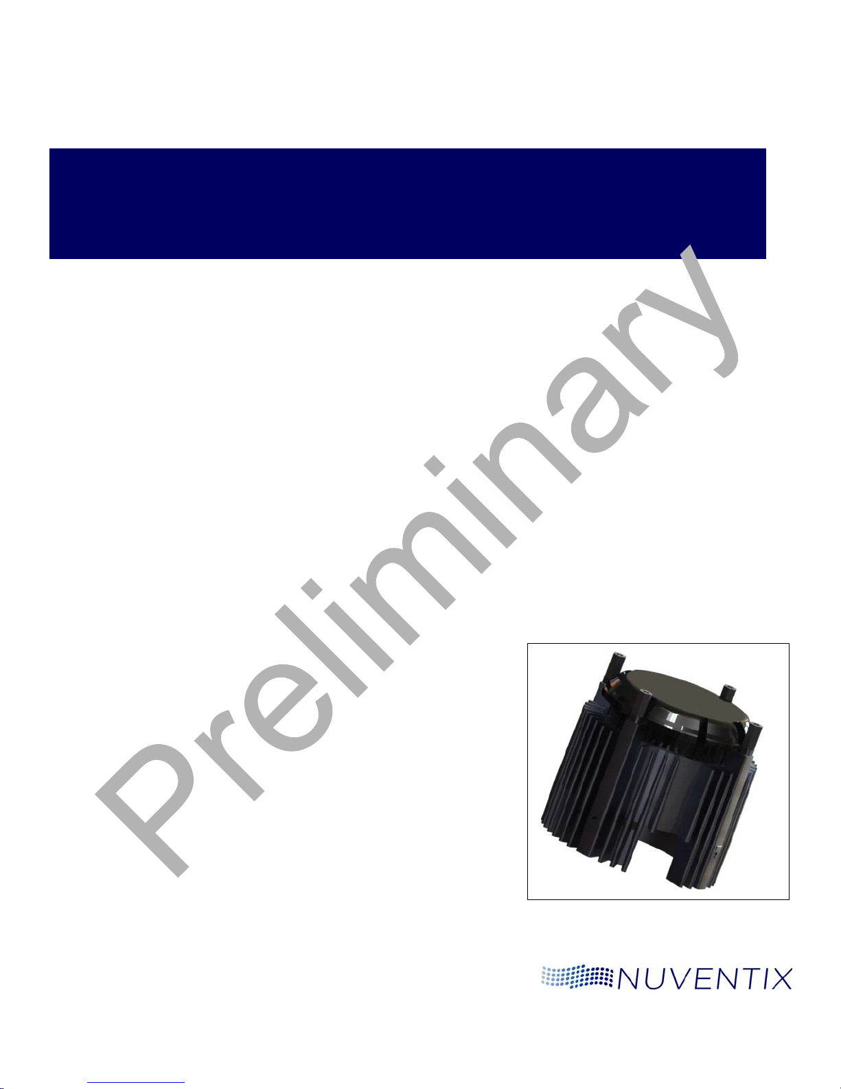
Chapter 1: Introduction SynJet Spot Light Cooler with Heat Sink Assembly Guide
Page 8 Nuventix February 2010
Handling The thermal, mechanical, and electrical integrity of the luminaire can be
significantly influenced in the assembly process.
The LED drive circuit, the SynJet driver circuit, plus other power and control
circuits in the luminaire, have typical industry levels of built-in ESD tolerance.
However, unusual environmental conditions and handling can create exceptional
levels of ESD that could cause damage.
IMPORTANT! Electrostatic Discharge (ESD) is a significant cause of electronic
circuit failure. A failure may:
be immediate
occur later due to a weakened component
appear as an early service life failure.
An industry-standard assembly and test area must have proper
ESD protected work stations. In addition, the staff must have ESD
prevention education.
The SynJet Spot Light Cooler electronics require
industry-standard care and use of proper ESD protection during
assembly and test.
When handling the SynJet Spot Light Cooler, use care with the wiring and the
circuit card. The SynJet Spot Light Cooler is designed for normal assembly
operations. With excessive force, the wires and components can be over-stressed
and broken.
The SynJet Spot Light Cooler plastic housing has been designed to withstand
normal assembly forces. Clamping or force fits can create very strong local forces
that could damage or weaken the cooler housing, thus creating an early life failure
risk.
The SynJet Spot Light Cooler contains magnets. Small particles of iron, screws,
and other magnetic materials from secondary machining or that are loose in the
assembly area may be attracted to the housing or the PCBA. They could interfere
with performance or cause a failure. Be sure any particles are removed after
machining and the assembly work area is clean.
If secondary machining operations are performed on the heat sink, remove the
SynJet Spot Light Cooler to avoid damage to the housing or circuit card.
Thermal Interface Material Thermal interface material (TIM) is important between surfaces that transfer heat.
Refer to the SynJet Spot Light Cooler with Heat Sink Design Guide for additional
information on selection and use of TIM.
For the best heat transfer, properly clean and prepare the transfer mating
surfaces. Refer to the TIM supplier's recommendations for surface preparation.
Nuventix does not specify or supply a specific TIM. This is the responsibility of the
luminaire design team's thermal engineer. Nuventix Sales can provide support
and consultation.