GPS RF Front End User Manual
Rev 1.0
6
these guidelines will prevent damage to the power amplifier or external equipment.
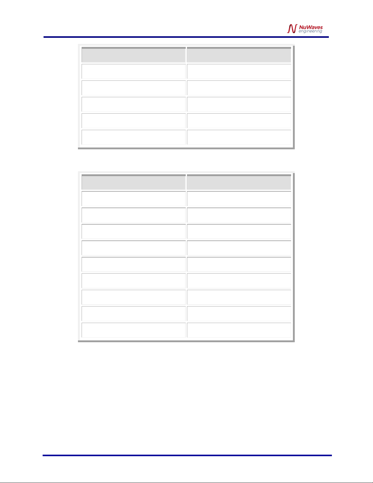
3.1 POWER SUPPLY REQUIREMENTS
To operate the GPS RF Front End, ensure that the power supply has adequate overhead to source the
current demand of the RF power amplifier. The power supply source must provide a typical voltage of
+28 VDC with greater than 5 amps capability.
3.2 CONNECTING A PROPER LOAD TO THE ANTENNA TERMINAL
To prevent damage to the GPS RF Front End, the antenna terminal must be terminated into a 50 Ω load.
Examples of a proper load include:
•Directly connecting to an antenna specified for the frequency range (960 MHz to 1390 MHz).
Connecting to an inappropriate antenna may result in damage to the front end module.
•Connecting to a proper antenna through a 50 Ω transmission line or coaxial cable. Avoid using
damaged cables or corroded connectors while attaching the unit to an antenna.
•Terminating the antenna terminal into a 50 Ω power attenuator with minimum 20 dB attenuation.
•Connecting to a load capable of dissipating the RF power from the front end module. Loads
capable of handling 50 Watts (min) are recommended.
3.3 POWERING-UP THE GPS RF FRONT END
The GPS RF Front End must be terminated to a proper load before power is applied. Refer to Section 3.2
for the specifications of the proper load. After the front end is properly terminated, the interface cable
can be connected to the unit and power can be applied. The front end is now ready for operation.
3.4 TRANSMIT TURN-ON TIME
The GPS RF Front End is at full power approximately 1 μS after the RF Enable line goes low (ground).
Therefore, transmit data can be applied to the input after 1 μS without loss of data.
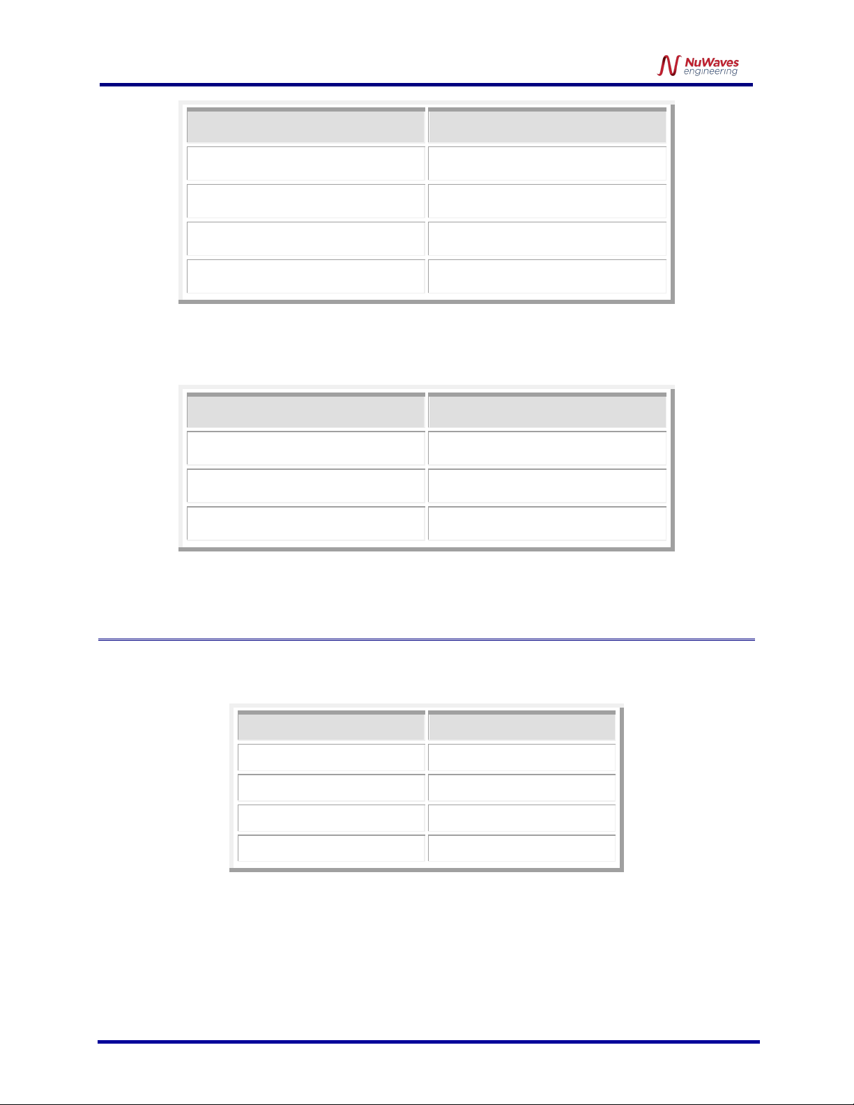
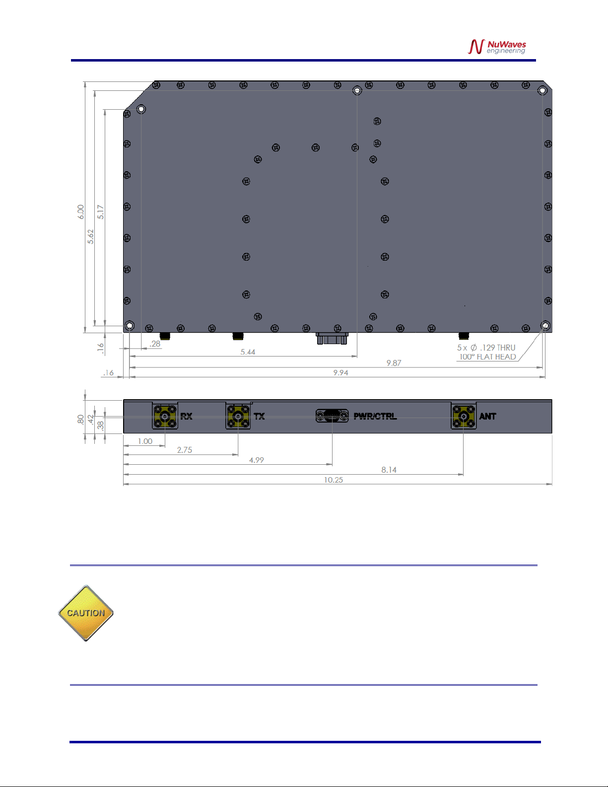
4HARDWARE INTERFACE
•The TX IN connector is SMA (female)
•The RX OUT connector is SMA (female)
•The ANT connector is SMA (female)
The pin-out definitions for the 9 pin Micro-D socket connector are provided in Table 6. In a typical
installation, the GPS RF Front End module is mated to a host controller board via a cable harness.
The RF Out SMA connector is the antenna connection. This connection should always be loaded
into 50 Ω, otherwise the front end could be damaged.