South Galaxy G5 User manual

- 1 -
SOUTH G5 GNSS Positioning System
User Manual

- 2 -
Contents
Contents .......................................................................................................................................- 2 -
Chapter Ⅰ Preface ......................................................................................................................... - 4 -
§1.1 Introduction ................................................................................................................. - 4 -
§1.2 Applications .................................................................................................................- 4 -
§1.3 Main Features ..............................................................................................................- 5 -
ChapterⅡHardware Component ...............................................................................................- 6 -
§2.1 Receiver components .................................................................................................. - 6 -
§2.2 Bottom Components ....................................................................................................- 7 -
§2.3 Indicators and Keypad .................................................................................................- 8 -
§2.4 Touch screen ................................................................................................................- 9 -
§2.5 Receiver Menu ............................................................................................................ - 9 -
§2.5.1 Main display interface ......................................................................................- 9 -
§2.5.2 Main menu ......................................................................................................- 11 -
§2.5.3 Power off, Reset, Set default and Self-check .................................................- 12 -
§2.5.4 Set work mode ................................................................................................- 13 -
§2.5.5 Set datalink mode ...........................................................................................- 16 -
§2.5.6 System option .................................................................................................- 19 -
§2.5.7 WIFI config .................................................................................................... - 21 -
§2.5.8 USB mode config ........................................................................................... - 21 -
ChapterⅢWeb UI Management ..............................................................................................- 22 -
§3.1 Overview ................................................................................................................... - 22 -
§3.2 Access by WiFi ..........................................................................................................- 22 -
§3.3 Access by USB .......................................................................................................... - 23 -
§3.4 Web UI main interface .............................................................................................. - 24 -
§3.4.1 Status .............................................................................................................. - 26 -
§3.4.2 Configuration ................................................................................................. - 27 -
§3.4.3 Satellite Information ...................................................................................... - 33 -
§3.4.4 Data Record ....................................................................................................- 35 -
§3.4.5 Data Transfer .................................................................................................. - 36 -
§3.4.6 Network Config ..............................................................................................- 40 -
§3.4.7 Radio Config .................................................................................................. - 43 -
§3.4.8 Firmware Update ............................................................................................- 45 -
§3.4.9 Track Manage .................................................................................................- 48 -
§3.4.10 Coordinate System ....................................................................................... - 49 -
§3.4.11 Online Service .............................................................................................. - 49 -
§3.4.12 User Management ........................................................................................ - 50 -
§3.4.13 System log ....................................................................................................- 50 -

- 3 -
ChapterⅣAccessories ............................................................................................................. - 51 -
§4.1 Instrument Case .........................................................................................................- 51 -
§4.2 Charger ...................................................................................................................... - 51 -
§4.3 Cable ..........................................................................................................................- 52 -
§4.4 UHF Antenna .............................................................................................................- 52 -
§4.5 Other Accessories ......................................................................................................- 52 -
G5 Specifications ...................................................................................................................... - 53 -

- 4 -
Chapter Ⅰ Preface
Read this chapter, you will have a brief knowledge of SOUTH Company and G5
measurement system.
§1.1 Introduction
Welcome to South Surveying & Mapping Technology CO., LTD, which is China’s leading
manufacturer of surveying equipment including GNSS receivers and Total Stations. To know
more about SOUTH, please visit our official website https://www.southinstrument.com/
This manual takes G5 positioning system for example, to explain how to install, set up and uses
the RTK system as well as the use of the accessories. We recommend that you read these
instructions carefully before using the instrument.
§1.2 Applications
Control Survey: dual-band (dual-frequency) system static measurements can accurately
complete the high-precision deformation observation, photo-control point measurement.
Highway Survey: quickly complete the encryption of the control points, road topographic
mapping, cross-section measurement, profile measurement with K-survey.
CORS Application: provide more stable and convenient data link for field operations. It is
seamlessly compatible with all types of domestic CORS applications.
Data acquisition measurement: perfect match SOUTH various measurement software to do
quick and easy data acquisition.
Stakeout shot:large-scale point, line, plane lofting.
Electric Power Measurement:power line measurement orientation, ranging, angle calculation.
Marine application:oceanographic research, dredging, piling, inserted row, making the marine
operations more convenient and easier.

- 5 -
§1.3 Main Features
All Constellations and More Channels
With 1598 channels, G5 is capable to track signal from 5 satellite constellations , process signal
of up to 16 frequencies and provide stable and reliable accuracy.
More Powerful and More Durable
Thanks to the 3W Farlink radio, when it works as an UHF base station G5 is able to
transmit correction data farther than others, in optimal condition the working range
can be 10 to 15 km.The shock-resistant frame, water-proof frame all have been enhanced, now
the overall proof level is IP68.
Superior Endurance, Up to 25 hours working
The newly developed power management system allows G5 to work for 10 to 25
hours and can be recharged by a type-C connector.
Color Touch Screen, Makes Workflow Simpler
Users can operate G5 by touch screen and key buttons, easy and fast.
RTK-Keep
When G5 loses the RTK correction data source from base station, this function will
help receiver to maintain the precise position for a few minutes.
L-band Correction, 4-10cm PPP
G5 is able to receive B2b signal via L-band, and perform a single point positioning.
It is a great help to surveyors who work in particularly difficult areas. This service is
available in 2022 from Asian-Pacific region.

- 6 -
ChapterⅡHardware Component
Reading this chapter, you can grasp the components, installation and the function of
G5 positioning system
§2.1 Receiver components
UHF antenna port
Key pad
LCD touch screen
NFC

- 7 -
§2.2 Bottom Components
Type-c port: USB port, OTG interface and Ethernet port..
5-Pin port:
1. As a power port connected with an external power supply device.
2. As a differential transmission port connected with an external radio.
3. As a serial port to check data output and debug.
PPS Port:N/A
Speaker:Voice broadcast.
SIM Slot:Insert SIM card.
○
4Speaker
○
2 5 PIN LEMO port
○
3PPS port
○
1Type-C port
○
5SIM slot
- 8 -
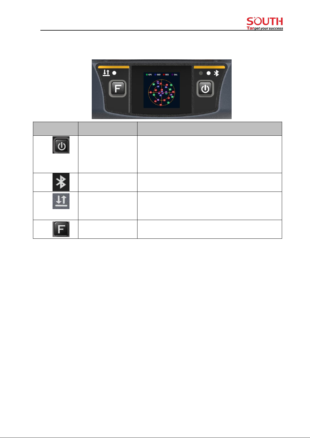
§2.3 Indicators and Keypad
Ref
Component
Description
Power Button
1) Power on/off
2) Select menu
3) In lowest menu: short press for select, long press for
confirmation
Bluetooth Indicator
Light on blue when Bluetooth connected
Data Indicator
Flash green when Fixed solution.
Flash red when not Fixed with the correction signal.
No Flash when no correction data.
Function Key
Shift between menus.
Keypad operation:
Fn key: Shift between options
PWR key:
1) Short press: select the option
2) Long press: to Power off (Reset, Set default, Self-check) receiver
3) Long press: to accept the configuration (when at the lowest menu), just like swiping down the
touch screen.
Press any key (or click on touchscreen) will wake up screen if screen sleeps.

- 9 -
§2.4 Touch screen
The receiver can be operated from both keypad and touch screen. By swiping the screen,
receiver can be configured.
1. Swipe right /left: to shift between options (or press Fn key to shift between options)
2. Tap screen: for selection (or short press PWR key for selection)
3. Swipe down:
----To bring up system menu [Power off], [Reset], [Set default], [Self-check] when it is at main
display interface
---- In lowest level menu: swipe screen down to accept the configuration (or long press PWR key
to accept the configuration).
4. Swipe up
Return from sub-menu to previous menu.
§2.5 Receiver Menu
§2.5.1 Main display interface
There are 2 main display interfaces: [Coordinates display interface], [Satellite display interface].

- 10 -
Icons in the Coordinates display interface
1) In static mode:
2) In Base mode:
3) In Rover mode:
Coordinates and
satellites
Static recording
Work in
static mode
Datalink: WIFI
Differential correction
data format
Datalink status
Solution status
Datalink: WIFI
Datalink status

- 11 -
§2.5.2 Main menu
Main menu: by swiping screen right or press F key to bring them out.
[Work mode], [Set Datalink], [System option],[Receiver information], there are two
methods to bring them up:
Method 1: by touch screen
From main display interface, directly swipe screen right, the LCD screen will show below
menus circularly as below.
[Work mode], [Set Datalink], [System option], [Receiver information], [Satellites display
interface], [Coordinates display interface] ... [Work mode], [Set Datalink] …
Tap screen to select the main menu in your need (or press PWR key to select).
Method 2: by Keypad
From main display interface, Press FN key, the LCD screen will show above menus
circularly and press PWR key to select the main menu (or tap screen to select).
When the receiver switched on, there are two main display interfaces: coordinates display
interface and satellite display interface. Swipe left or right to switch between the two main
display interfaces.
Work mode
To switch work mode between Static mode, Base mode and Rover mode.

- 12 -
System option
[WIFI config]: to set WIFI mode. There are two WIFI mode: AP mode and Client mode.
[Power saving mode]: to switch off the LCD display to save power.
[Other option (USB mode, Ethernet mode, Language)]: to change language and set USB
mode.
6) Receiver information
To show key information of receiver: serial number, firmware version, Expiry date.
§2.5.3 Power off, Reset, Set default and Self-check
Anytime when it is in main display interface, swipe screen down will bring them up.
System menu: [Power off], [Reset], [Set default], [Self-check]
By swiping screen down to bring system menu out (when it is at main display interface).
[Power off]: to power off receiver.
[Reset]: to restart receiver.

- 13 -
[Set default]: to restore to default settings.
[Self-check]: to do self-check for receiver.
§2.5.4 Set work mode
Swipe right (or Press F key) to select [work mode], then tap screen (or press PWR key) to
accept.
There are three work modes:Static mode, Base mode, Rover mode (as below image):
1. Static mode
1.1)Select static mode
Swipe right and select [work mode], then select [Static mode] (or press F key to select and
press PWR key to accept), the receiver will enter Static mode.
1.2)Static mode settings
Tap screen to bring up settings interface (or Press PWR key to bring settings interface)
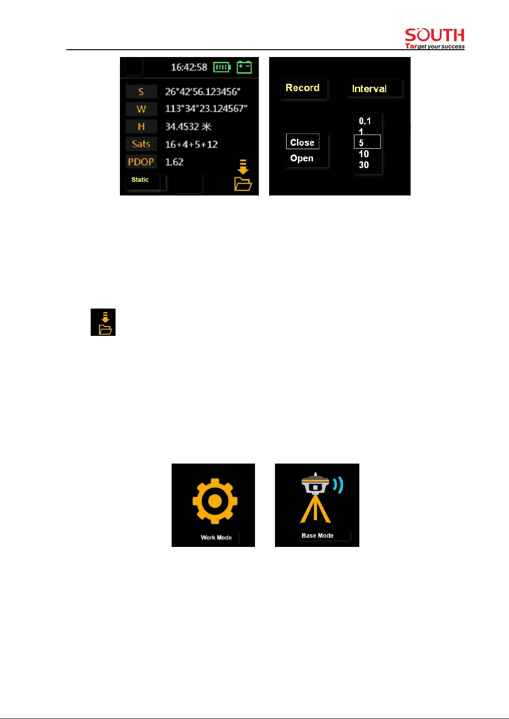
- 14 -
Set [Record: open] and your required recording Interval, then swipe down to accept (or
press and hold PWR key to accept) the settings.
Set [Record: close] to stop recording when your field record complete.
After make the settings, swipe screen down to accept (or long press PWR key (press PWR
key and hold it for 3 seconds)
Icon on lower right corner shows it is recording static data.
2.Base mode
2.1) Enter Base mode
Swipe right to select [Work mode], then select [Base mode] ((or press F key bring out main
menu and press PWR key to select [Work mode], then select [Base mode]), the receiver will
enter Base mode.
2.2) Base mode settings
Tap the screen to enter Base mode settings (or Press PWR key to bring up settings)

- 15 -
In coordinates display interface, you can also tap screen to enter Base mode settings.
3. Rover mode
3.1) Enter Rover mode
Swipe right to select [Work mode], then select [Rover mode] ((or press F key bring out main
menu and press PWR key to select [Work mode], then select [Rover mode]), the receiver
will enter Rover mode.
3.2) Rover mode settings
Tap the screen to enter Rover mode settings (or Press PWR key to bring up settings)
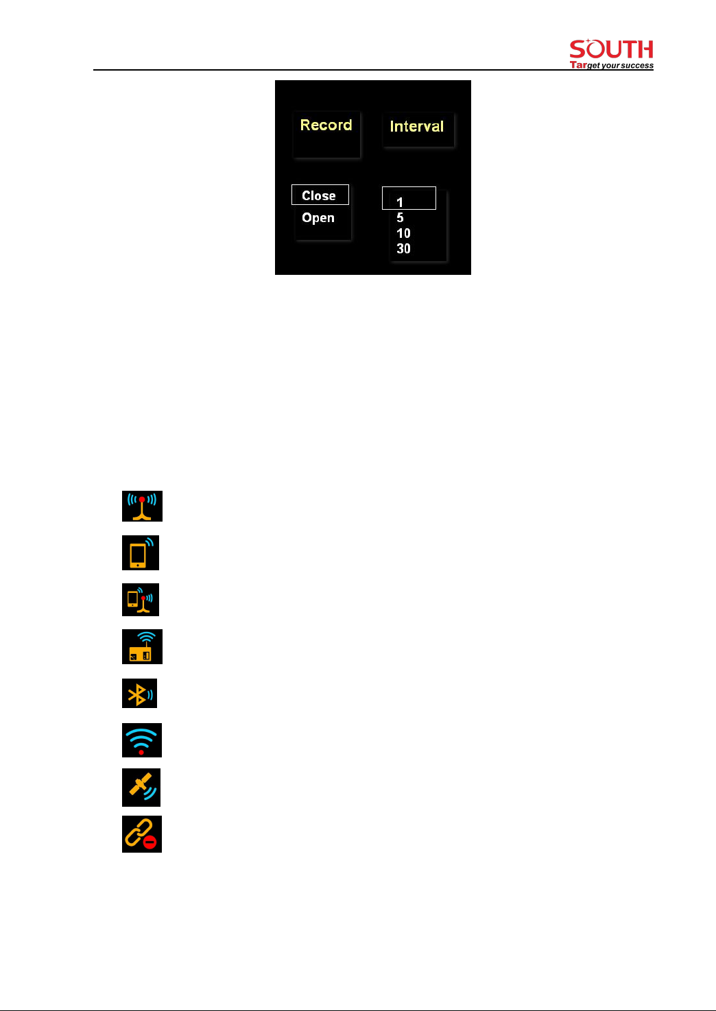
- 16 -
If you want the receiver to record static data during Rover mode, please set [Record: open]
and select recording interval.
Any time, you can view or change the settings of related work mode by tap the screen.
§2.5.5 Set datalink mode
There are 7 different type of datalink modes as below:
: UHF(Inbuilt radio) as datalink
: Cellular network (via SIM card) as datalink
: Dual transmit (inbuilt radio and cellular network)
: External radio as datalink
: Bluetooth datalink (also called controller network as datalink)
: WIFI datalink
: Slink(Satellite link)
: No datalink
1. UHF (inbuilt radio)
Firstly, set receiver to [Base mode] or [Rover mode], then enter Set datalink:

- 17 -
Swipe right and select [Set datalink], then select [UHF(inbuilt radio)] as below.
Tap the screen (or press PWR key) to make other settings for selected datalink.
Air baud rate: Normally, it is recommended to take default air baud rate. If need to change
it, please make the same change for both base and rover receiver. More air baud rate, more
data can be transmitted per second.
Radio protocol: Normally, it is recommended to take default protocol (Farlink). If need to
change it, please make same change for both base and rover receiver.
Radio power: to set the base inbuilt radio transmission power.
2. Cellular network
Utilizing the inserted SIM card, the receiver can access to cellular network and transmit the
differential correction data. Below icon shows the current datalink is cellular network.
3. Satellite datalink
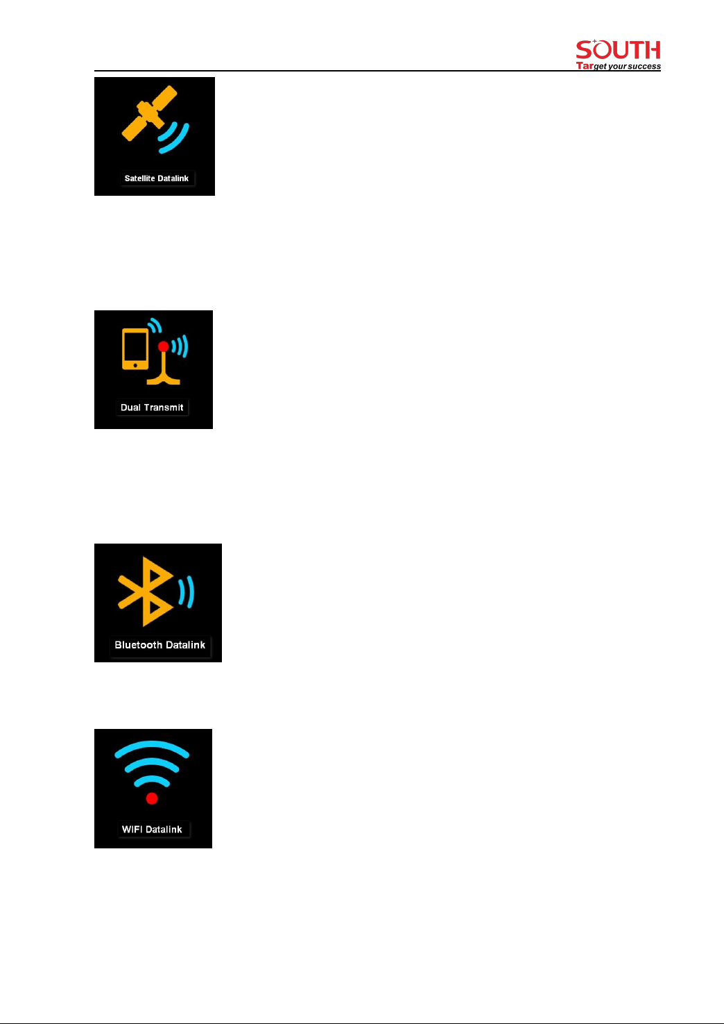
- 18 -
4. Dual transmit datalink
It means both inbuilt radio datalink and cellular network datalink:correction data is
transmitted simultaneously by both inbuilt radio and cellular network via SIM card.
5. Bluetooth datalink (also called controller network datalink)
Controller access to internet firstly and be connected to receiver by Bluetooth. Thus,
receiver can receive correction data by utilizing controller’s network.
6 WIFI datalink
Receiver access to WIFI network and transmit or receive differential correction data. It
needs to make setting: [System option]-[WIFI config]-[Work mode: client].
7. External radio datalink
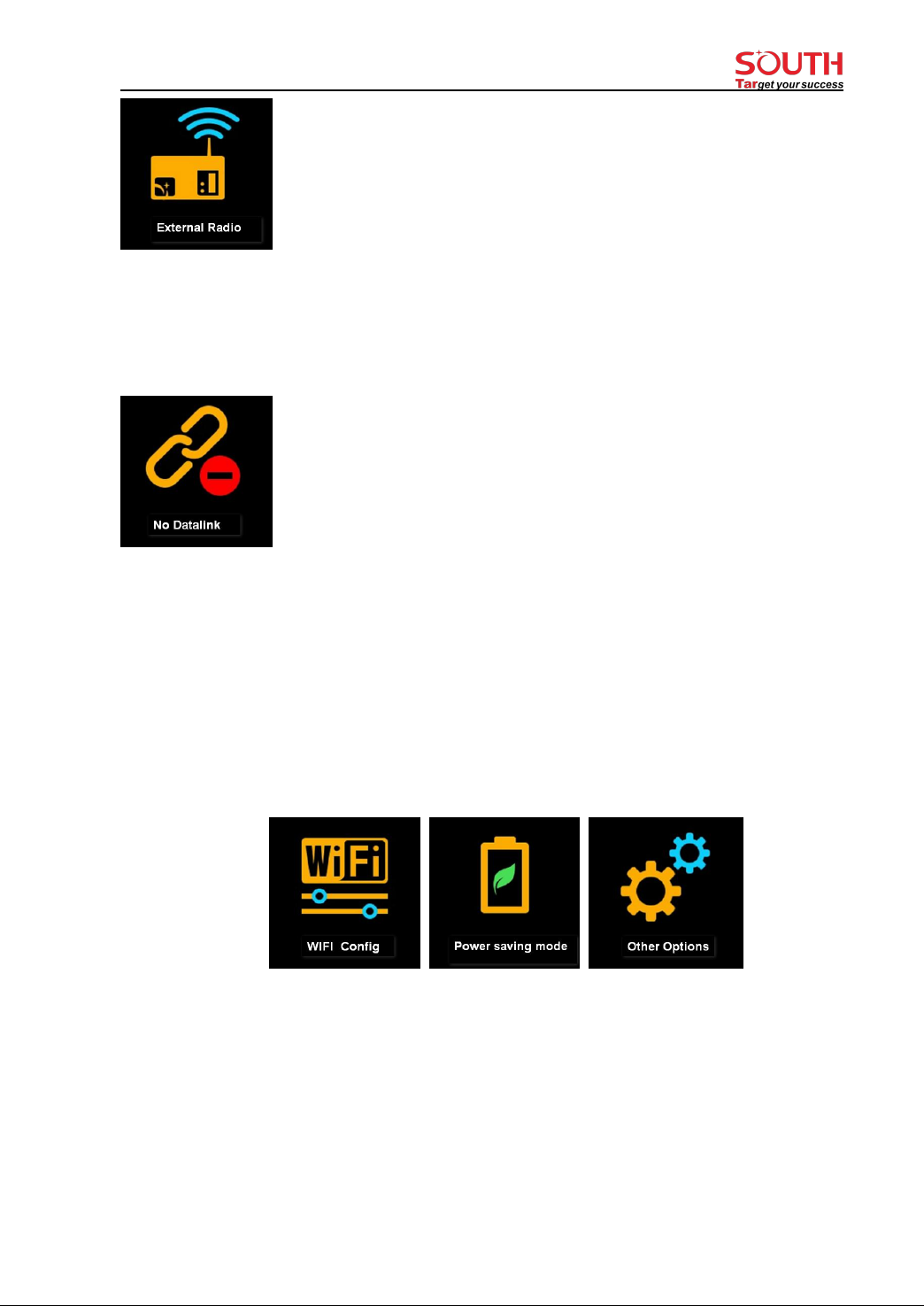
- 19 -
If an external radio is connected to receiver, then external radio datalink can be chosen as
datalink.
8. Close datalink
Choose this option to close all datalink. Usually it is used only for test or debugging
receiver.
§2.5.6 System option
Swipe right to select [System option] (or press F key to select), then tap it to accept (or press
PWR key to accept).
WIFI config
[WIFI work mode: AP/ Client]
AP mode: the receiver will generate hotspot so that your computer or mobile phone can
connected to it and visit receiver’s WEB UI.
Client mode: with the receiver’s inbuilt network module, it can connect other WIFI hotspot
to access to internet so that the WIFI datalink can be used.

- 20 -
Note: suggest to close WIFI client mode if there is no need to use WIFI datalink. By default,
it is set as AP mode.
Power saving mode
After choosing [power saving mode], the LCD display will turn dark in 2 minutes and once
you tap screen or press any keypad, the screen will be activated again. It is recommended to
set receiver in power saving mode to extend battery work time.
Other option
Language: select a language from here.
USB mode: USB flash disk mode and Ethernet mode.
Touch screen: enable or disable touch screen (if touch screen is disabled, you can use
keypad to set receiver menu).
Table of contents
Other South GPS manuals


