Page 2 of 2
PROGRAMMING
The sensor can be programmed via the infra-red handset to perform a number of lighting control functions, as
follows:
To operate the handset:
Check it has batteries installed. These are supplied with the handset.
Point the handset towards the sensor you wish to programme. Press the appropriate button on the
handset. When the fitting receives a command from the handset the fitting flashes on/off to show a
command has been received.
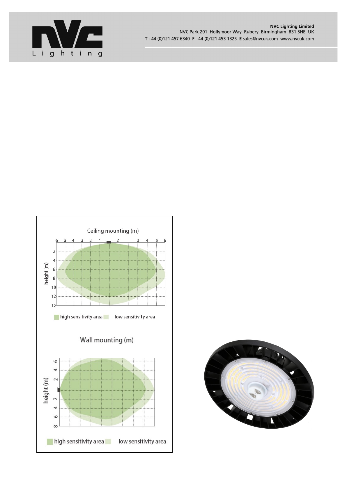
Note that the effective range of the handset is 12-15m
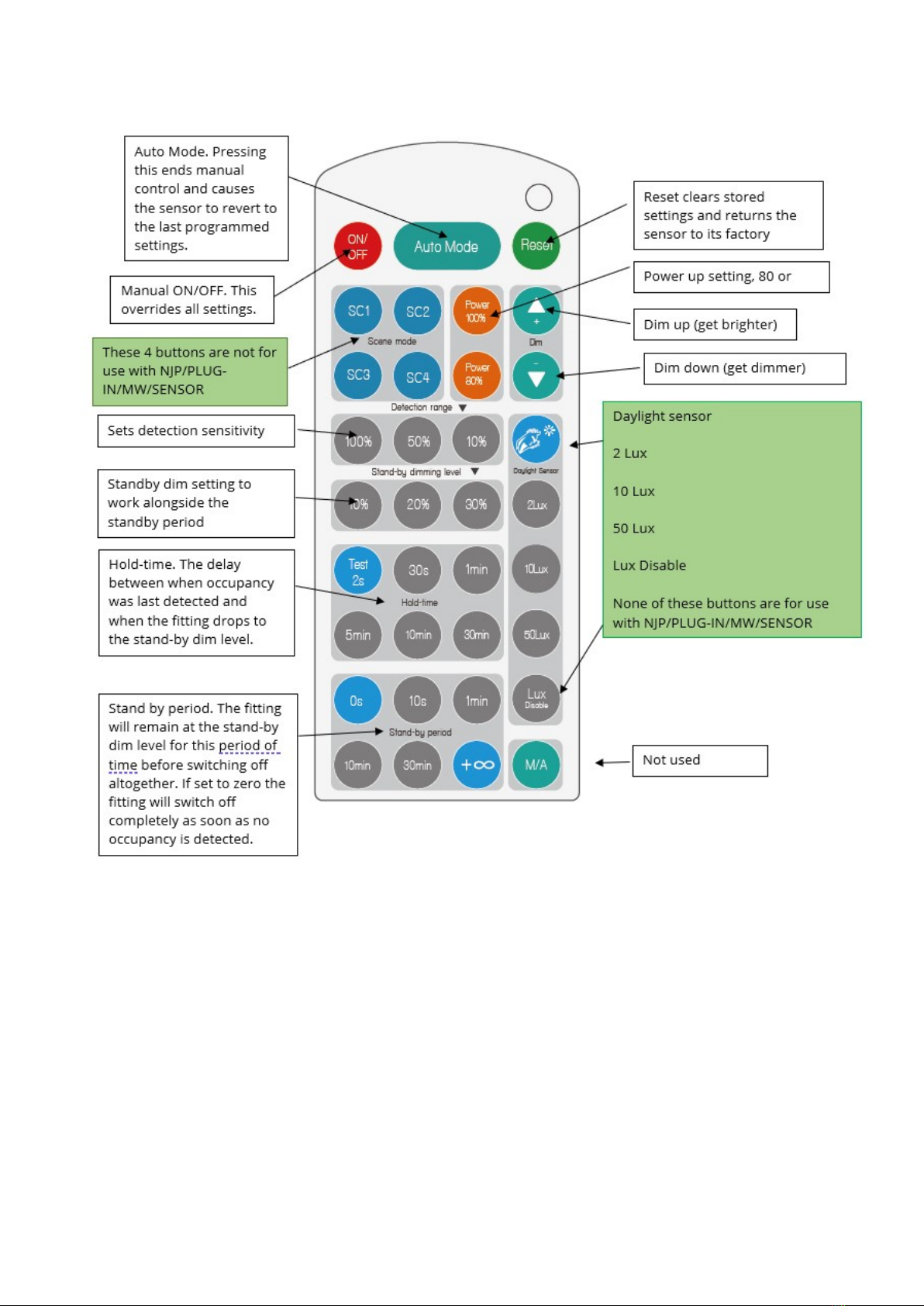
Manual on/off control
Press the red ON/OFF button. This places the fitting under manual control. Pressing this button switches the
fitting on and off. To end manual control, press Auto Mode, RESET or one of the scene buttons (SC1, SC2 etc)
Auto mode
Pressing this takes the fitting out of manual control. It will now function according to whatever settings have been
programmed in the sensor.
Reset
Pressing the Reset button returns the sensor to the original factory settings.
Power 100% / Power 80%
Press either of these two buttons to select the power-up output level of the fitting. When the fitting switches on it
will power up to 100% or 80%, according to the button you have pressed. Powering up to 80% is an energy
saving option. 80% can also be used when a fitting is new, but as lumen depreciatiion sets in as the fitting ages
the power-up level can be increased to 100% in compensation.
Dim+ / Dim-
A long press on these buttons causes the fitting to dim up (get brighter) or dim down (get dimmer). This is used
to manually adjust the output of the fitting.
Detection range
Select 100%, 50% or 10%. At 100% the micro-wave occupancy sensing will be at maximum sensitivity (and
longest range). At 10% the sensor will be at its least sensitive.
Stand-by dimming level
This is the light output that the fitting will revert to when presence is no longer being detected and the hold time
has elapsed.
Hold-time
This is the time that must elapse from the last movement being detected till the fitting drops from its power-up
level (80% or 100%) down to its stand-by dimming level.
Stand-by period
This is the time that the fitting will remain at its stand-by dimming level before switching off completely.
If you select “0s” the fitting will switch off directly after the Hold-time has elapsed
If you select “+∞” the fitting will remain at the Stand-by dimming level indefinitely. When presence is next
detected it will dim up to the 80% or 100% level.
Please note:
The handset can be used with several different sensors, each with different functionality and for use in different
lighting control applications. Therefore, not all the buttons on the handset are effective for use with the JUPITER
sensor. Please do not attempt to use any handset buttons except those described below.
The following buttons on the infra-red handset NJP/MW/PROG/HS are NOT for use with the
sensor NJP/PLUG-IN/MW/SENSOR- SC1, 2, 3, 4 -these buttons are not for use with the JUPITER
sensor.
Daylight sensor, 2 lux, 10 lux, 50 lux, lux disable-these buttons are not for use with the JUPITER
sensor.If you press any of these buttons the sensor will react unpredictably. If you experience this,